basIP SP-03 User manual

SP-03
SP-03
Exported on 02/10/2020

– 2
Table of Contents
Device description................................................................................................. 4
Technical parameters........................................................................................... 5
Main features ...................................................................................................................................5
FUNCTIONAL CAPABILITIES....................................................................................................5
Configuration through WEB interface........................................................... 6
Login .................................................................................................................................................. 6
Dashboard ....................................................................................................................................... 6
Device information........................................................................................................................................................6
Do not disturb mode ....................................................................................................................................................7
Intercom ............................................................................................................................................7
Address Settings............................................................................................................................................................7
DTMF ..................................................................................................................................................................................9
Advanced intercom settings ...................................................................................................................................10
Calls forward..................................................................................................................................................................10
SOS/Concierge button ..............................................................................................................................................10
Network ............................................................................................................................................ 11
Network configuration................................................................................................................................................ 11
Custom NTP.................................................................................................................................................................... 11
Management system .................................................................................................................................................. 12
System ............................................................................................................................................. 13
Language ........................................................................................................................................................................ 13
Settings............................................................................................................................................................................ 13
Firmware upgrade....................................................................................................................................................... 13
Reboot ............................................................................................................................................................................. 14
Installation and connection............................................................................... 15
Completness check of the product ...................................................................................... 15
Electrical connection.................................................................................................................. 15
Mechanical mounting .................................................................................................................16
Connection of additional modules........................................................................................ 18

Device description– 4
•
•
•
•
•
•
•
•
•
•
•
•
•
•
Device description
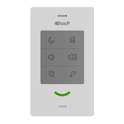
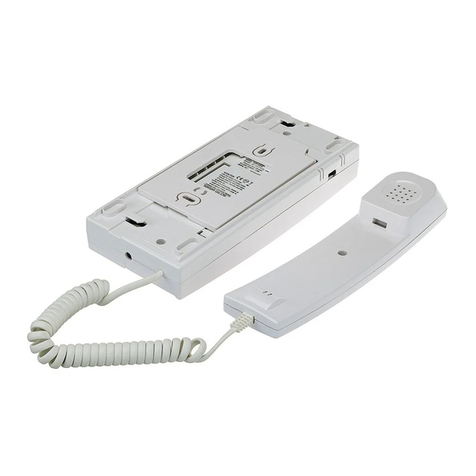
Subscriber IP audio device with support for SIP, P2P and internal BAS-IP protocol.
Functional 6 buttons, from left to right, from bottom to top:
Answer an incoming call/end a call;
The opening of the lock. Automatically receive settings from Link software;
Reduce the overall volume level (6 volume levels, changes when playing an incoming call
melody). Mute the microphone (during a call);
Increase the overall volume level (6 volume levels, changes in the playback mode of the
incoming call melody and cyclically during a call);
DND - disabling the ringtone for an incoming call, only the indicator light flashes;
Concierge call.
Indicator statuses:
The device in standby mode - constant white backlight;
Incoming / outgoing call - flashing green backlight;
Conversation - constant green backlight;
DND is on - constant red backlight;
A signal to open the lock was sent - a flashing white and green backlight 3 times in 1.5.-2
seconds;
Mute during a conversation - slowly flashing red and green lights;
Pressing the volume button - flashing white backlight 1 time, then return to the backlight
of the current mode;
The mode for automatically receiving settings is the flashing red, green, and blue
backlight.
Additionally:
Network connection: Ethernet 10/100;
Power: + 12V and PoE 802.3af;
Connection of an additional handset SP-AU.

Technical parameters– 5
•
•
•
•
•
•
•
•
•
•
•
•
•
Technical parameters
Main features
Number of VoIP accounts supported: 1
Supported protocol type: IPv4
Network connection: 1 PoE port IEEE 802.3af
Power supply: 1 PoE IEEE 802.3af port and 1 +12 Volt connection port
Supported codec type: G.711μ/ A
Additional function: Doorbell
Audio transmission method: Full Duplex
Number of control keys: 6
Configuration and programming method: WEB-interface
Installation method: Wall-mounted
Overall dimensions: 184 × 106 × 28 mm
Available colors: Black, white
FUNCTIONAL CAPABILITIES
Support for internal BAS-IP protocol
Support for SIP 2.0 and Peer-to-peer SIP, for organizing communication with any VoIP
equipment supporting this protocol
Opening door lock
Concierge Monitor Calls
SIP call forwarding
DND
Mute
Display of various device statuses using the indicator light
6 volume levels
Link software support
Support for receiving automatic settings from Link
Backup and restore settings
Possibility of receiving software updates from the BAS-IP server and user update server

Configuration through WEB interface– 6
•
•
•
•
•
Configuration through WEB interface
Login(see page 6)
Dashboard(see page 6)
Intercom(see page 7)
Network(see page 11)
System(see page 13)
Login
To search for a device on the network, you can use the software for searching and firmware
upgrade.
In the Internet browser, in the address entry box, you must enter the IP address of the device,
after which the user name and password entry window will appear.
Username to enter the settings: admin.
The password required for entry corresponds to the password for accessing the settings of the
device and is the installer password (default password: 123456).
Dashboard
Device information

Configuration through WEB interface– 7
Framework:Version of Framework.
Web Server:Version of Web server.
Firmware version:Version of the firmware.
Device type:Device type.
Device name:Name of the device.
Device serial number:Device serial number.
MAC address:MAC address of the device.
Do not disturb mode
Enable/Disable:Enable/disable the do not disturb mode.
Intercom
In this menu, the logical address settings are set for the device to communicate with the call
panels.
Address Settings
In the do not disturb mode the device will receive calls without a sound, only the green
LED will blink. In the stand by mode, red LED will light.
To enable this mode directly from the device, you need to press the top left button on
it.

Configuration through WEB interface– 8
Building: Building number.
Unit:Unit number.
Floor: Floor number.
Apartment: Apartment number.
Device number: Sequence number of the device.
SIP settings
Enable/Disable: Enable/disable SIP registration.
Proxy: A proxy SIP server that can be represented by both an IP address and a domain name.
If the device is one, it is necessary to set "0" in this line. If there are several devices,
then the numbering should begin with "0" and end with "8".

Configuration through WEB interface– 9
Realm: SIP server address.
STUN IP: Server STUN address.
STUN port: STUN server port.
User: SIP number.
Password: Password from SIP number.
DTMF
Default value: Enable/disable the function of sending a standard value when the lock open
button is pressed (the internal protocol command to open the door).
Lock code: DTMF code transmitted when the lock open button is pressed.
Before the proxy address, you must specify "sip:".
It can be specified as an IP address or a domain name.
stun.l.google.com.
Port 19302 is used for the STUN server of Google.
100

Configuration through WEB interface– 10
Advanced intercom settings
Talk volume level: Adjust the speaker volume of the device during the call.
General volume level:Adjust the volume level of the speaker in the stand by mode.
Maximum call time: The time interval after which the device automatically end an outgoing call.
Calls forward
Total count: The number of active redirects (up to four redirects).
URL: Direction for parallel call forwarding when an incoming call is made to the internal monitor.
SOS/Concierge button
By default, the call panels are configured to receive a DTMF code "#" to unlock the
lock.
To mute the microphone during the call, you need to press the "Volume down" button.
You can also adjust the speaker volume level during an incoming call.
Example
Forwarding to the specified directions is activated when making calls to the handsfree
using an internal protocol.

Configuration through WEB interface– 11
SOS/Concierge button:Enable/disable the function to call the specified SIP number by
pressing the button to call the concierge on the device. If this feature is disabled, the
concierge will be called using an internal protocol.
URL: SIP number input field, which will be called when pressing the concierge button.
Network
Network configuration
DHCP: Enable/disable the auto retrieve network settings feature.
IP: Device IP Address.
Mask: Subnet mask.
Gateway: The main gateway.
DNS: DNS server address.
Custom NTP
By default, the device can have a static IP address 192.168.1.90 or 192.168.1.91.

Configuration through WEB interface– 12
Custom NTP: Enable/disable the use of a custom NTP server.
Current device date/time:The current time and date of the device.
NTP URL: Custom time server input field.
Time Zone: Select the time zone to use.
Management system
Link Server: The address of the PC or server where the Link monitoring and control system for
the intercom system is installed.
Password: Password to access the server.
Heartbeat to server: Enable/disable sending device status to a server with Link software
installed.
To automatically receive device settings from the Link server and further interact with
it, you need to create a device in the server interface, specify the required settings for it
and click the device initialization button (magnifying glass icon with circular arrows).
From the side of the device, in standby mode, hold down the button with the image of
the key for 5 seconds, and then release it. Alternating flashing of LEDs indicates that
the device is in the mode of automatically receiving settings from the server flow, in
which the device can be up to 60 seconds.
Upon successful initialization, the device will play the corresponding sound, the
indicator light will flash green 3 times and switch to normal operation.
If initialization is unsuccessful, it will play the corresponding sound and enter normal
operation mode.

Configuration through WEB interface– 13
System
Language
Selection device language.
Settings
Choose file: Select a monitor configuration file from the PC file system.
Backup settings: Save and export monitor configuration files.
Reset to default settings: Reset all internal monitor settings to factory settings.
Firmware upgrade

Configuration through WEB interface– 14
Custom server: Enable/disable the use of a custom update server. Used in closed networks of
door intercommunication.
URL: The input field for the IP address or domain of the custom update server.
Choose file: Select a software update file from the PC file system.
Check for updates: Check for software updates on the BAS-IP server or user server.
Update firmware: Start firmware update.
Reboot
Reboot: Soft reboot of the monitor.
Software update features:
When updating the system via WEB or a graphical interface, a backup copy of all
applications installed on the monitor is automatically created, and all configuration files
are saved. Each subsequent update will overwrite the backup file.

Installation and connection– 15
•
•
•
•
•
•
•
Installation and connection
This page describes how to install and connect the device.
Completness check of the product(see page 15)
Electrical connection(see page 15)
Mechanical mounting(see page 16)
Connection of additional modules(see page 18)
Completness check of the product
Before installing the monitor, be sure to check its completeness and the presence of all
components.
The kit includes:
Device 1pc
Installation manual 1pc
Installation screws 2pcs
Wall mounting bracket 1pc
Electrical connection
After verifying whether a device is complete, you can switch to the connection.
For connection you will need:
An Ethernet UTP CAT5 or higher cable connected to a network switch/router.
Power supply at + 12V, 2 amps if there is no PoE.
Wires must be brought for connecting the additional modules (optional).
Cable length recommendations
The maximum length of the UTP CAT5 cable segment should not exceed 100 meters,
according to the IEEE 802.3 standard.

Installation and connection– 16
Mechanical mounting
Before installing the monitor, you must provide a hole or recess in the wall with a diameter of 68
mm for a standard mounting box for a 65 * 45 mm outlet. This is necessary for switching wires
and mounting the monitor.
The bracket is fixed in the socket by using the supplied screws and a cross-head screwdriver.
The monitor is mounted on the bracket from top to bottom.

Installation and connection– 17
Before installing the monitor with the SP-AU handset, it is necessary to fasten the bracket for
the tube on the backside as shown in the diagram below:

Installation and connection– 18
•
•
•
Connection of additional modules
Optional handset SP-AU
External siren (siren is activated when one of the alarm sensors is triggered)
Call button on one of the alarm loops
Other manuals for SP-03
2
Table of contents
Other basIP Intercom System manuals
basIP
basIP AQ-07LL User manual

basIP
basIP AA-14FBS User manual
basIP
basIP AV-04SD User manual
basIP
basIP AZ-07LL User manual
basIP
basIP AV-03BD User manual
basIP
basIP AA-07FB User manual
basIP
basIP AQ-07LA User manual
basIP
basIP AA-12 Series User manual
basIP
basIP AV-08FB User manual
basIP
basIP AV-01 Instruction sheet

