Baumer NE216 User manual

NE216
www.baumer.com 23
Operating Instructions
Electronic preset counter
NE216
Contents Page
General / Safety instructions 24
System description 26
Description 26
Block diagram 26
Connecting 27
Connecting the voltage supply 28
Assignment signal output „relay“ 28
Assignment signal output „electronic“ 29
Assignment signal inputs 29
Typical connections 30
Connecting the sensor supply 30
Interface connection 31
Operating mode 31
Key functions 31
Programming mode 33
Operating and preset mode 38
Counting modes (input mode) 39
Output responses (output mode) 40
Technical data 41
Dimensions 43
Error messages 43
Part number 44

NE216
24 www.baumer.com
General Information
In the following you will find the explanations of the symbols used
in this operating manual.
Explanation of symbols «This symbol indicates activities to be carried out.
OThis symbol indicates supplementary technical information.
This symbol is located before texts to which particular attention is to
be paid to ensure proper use of the product.
This symbol is located before texts that provide important additional
information
Italics To help you quickly locate information, important terms are printed in
italics in the left text column.
1 Safety instructions
General information
The products has been developed and built in accordance with the
recognized rules of technology. The units have left the manufacturing
plant ready to operate and in safe condition.
To keep the units in this condition, it is necessary that the units be
- installed and operated
- properly,
- in a safety and hazard-conscious manner,
under observance of this operating manual and in particular of these
safety precautions!
Make sure that the personnel has read and understood the operating
manual, and in particular the „Safety Instructions“ chapter.
In addition to the operating manual, the generally applicable legal and
other binding regulations for accident prevention and environmental
protection must be observed and ensured.
This manual is intended as a supplement to already existing docu-
mentation (catalogues, data sheets or assembly instructions).
Proper use
The application of the units consists of controlling and monitoring
industrial processes in the metal, wood, plastics, paper, glass and
textile industry etc.
The units may only be operated
- in the properly installed state and
- in accordance with the specifications of the technical data

NE216
www.baumer.com 25
Operation not covered by the specified descriptions/parameters is
improper and can lead to
- fatal injuries,
- serious damage to health,
- property damage or
- damage to the units
in conjunction with the systems/machines/processes to be
controlled/monitored!
The overvoltages to which the units are subjected at the connection
terminals must be limited to the value of the overvoltage category II
(see Technical data)!
The units may not be operated
- in hazardous areas,
- as medical units,
- in applications expressly named in EN 61010!
If the units are used to control/monitor machines or processes with
which, as the result of a failure/malfunction or incorrect operation of
the units
- a life-threatening danger,
- health risks or
- a danger of property or environmental damage
could result, then appropriate safety precautions must be taken!
Do not open the housing of the units or make any changes to it!
Tampering with the units can have a negative affect on their opera-
ting safety, resulting in dangers!
Do not make repairs on the units! Return defective units to the ma-
nufacturer!
Installation/commissioning
In case of changes (including in the operating behavior) that impair
safety, shut-down the units immediately. During installation work on
the units, the power supply must always be disconnected. Installati-
on work may only be carried out by appropriately trained experts.
Maintenance/repairs
Always disconnect the power supply of all units involved. Main-
tenance and repair work may only be carried out by appropriately
trained experts.
If troubleshooting is unsuccessful, do not continue to use the units.
Please contact the manufacturer in this case.

NE216
26 www.baumer.com
2 System description
2.1 Description
The device comprises
- a 5-digit preset counter with 2 settings
- an 8-digit totalizer
LED display
P1 Preset 1
P2 Preset 2
P1 blinks, preset P1 reached
P2 blinks, preset P2 reached
Control panel
Key for display of functions, confirmation key
Reset
Key to select HIGHER decades
Key to select decades to the LEFT
2.2 Block diagram
Voltage
supply
Signal input
A
B
Control input
1
2
Totalizer
Interface
RS485
A 90° B Main counter
with 2 presets
start count
scaling factor
Operating
time meter
T,R-
T,R+
1
2
3
4
5
6
7
8
9
10
12
13
14
15
P2
Output
Sensor
supply
+
-
P1
+
-

NE216
www.baumer.com 27
3 Connecting
This section describes the terminal assignments, accompanied by an
example of a typical connection.
Sections 3.1 to 3.6 contain specific instructions and technical data
relating to the individual terminals.
Assignment Relay outputs Electronic outputs
9ROWDJHVXSSO\
75
3 3
75
±
75
%
$
56
6HQVRU
VXSSO\
&RQWURO
LQSXW
6LJQDO
LQSXW
WHUPLQDOWHUPLQDO
PD[9
WHUPLQDO
2XWSXWV
9ROWDJHVXSSO\
75
3 3
75
±
75
%
$
56
6HQVRU
VXSSO\
&RQWURO
LQSXW
6LJQDO
LQSXW
WHUPLQDOWHUPLQDO
PD[9
WHUPLQDO
2XWSXWV
Connecting assignment
Relay outputs and electronic outputs
Terminal Function
1
2
3
4
5
6
7
8
9
10
11
12
13
14
15
Voltage supply (-)
Voltage supply (+)
Relay output / Output P1
Relay output / Output P2
Signal input Track A
Signal input Track B
Control input 1 (main counter Reset)
Control input 2 (main counter Stop)
-
Sensor supply (+)
Sensor supply (-)
Option RS485 (T,R-)
Option RS485 (T,R+)

NE216
28 www.baumer.com
Litz contact only by means of connector sleeves with insulating
enclosures for reasons of shock protection according to EN 61010.
Do not otherwise assign contacts that have been left unassigned ex
factory. We recommend to screen all sensor terminal leads and to
ground the shield on one side. Shields on both sides are recommen-
ded in case of RF interference or in case of equipotential bonding
over long distances. The sensor leads should not be in the same
phase winding as the mains supply and the output contact leads.
3.1 Connecting the voltage supply
Three voltage supply are available:
AC voltage: 24/48 VAC (50/60 Hz), set the required alternating vol-
tage with the voltage selector switch.
AC voltage: 85...265 VAC (50/60 Hz), wide range supply
DC voltage: 12...30 VDC
Supply voltage Recommended external protection
24 VAC ±10 % M 400 mA
48 VAC ±10 % M 400 mA
85...265 VAC M 315 mA
12...30 VDC M 400 mA
voltage selector
«Model 24/48 VAC: set the required alternating voltage with the
voltage selector switch.
«Connect AC at the contacts 1 and 2 according to the terminal
diagram.
DC-voltage 12...30 VDC:
Connect interference-free voltage supply. Therefore, do not use the
voltage supply for parallel supply of drives, contactors, electroma-
gnetic valves, etc.
Fire protection: Operate instrument on the MAINS with external fuse
recommended on the type label. In case of disturbance, make sure
that 8 A /150 VA (W) are never exceeded – as defined under
EN 61010.
3.2 Assignment of signal outputs (relay contacts)
65
Contact P2
43
Contact P1 The signal outputs (contacts 3, 4 and 5, 6) are floating relay
contacts. The signal outputs can be assigned as per the adjacent
terminal diagram.
The type of outputs, as momentary or latched signal, can be cho-
sen in the programming lines 41 / 42.
Their function, as normally open or closed, is selected in program-
ming line 40.

NE216
www.baumer.com 29
Max. rating Max. voltage Max. current
150 VA/30 W 250 V 1 A
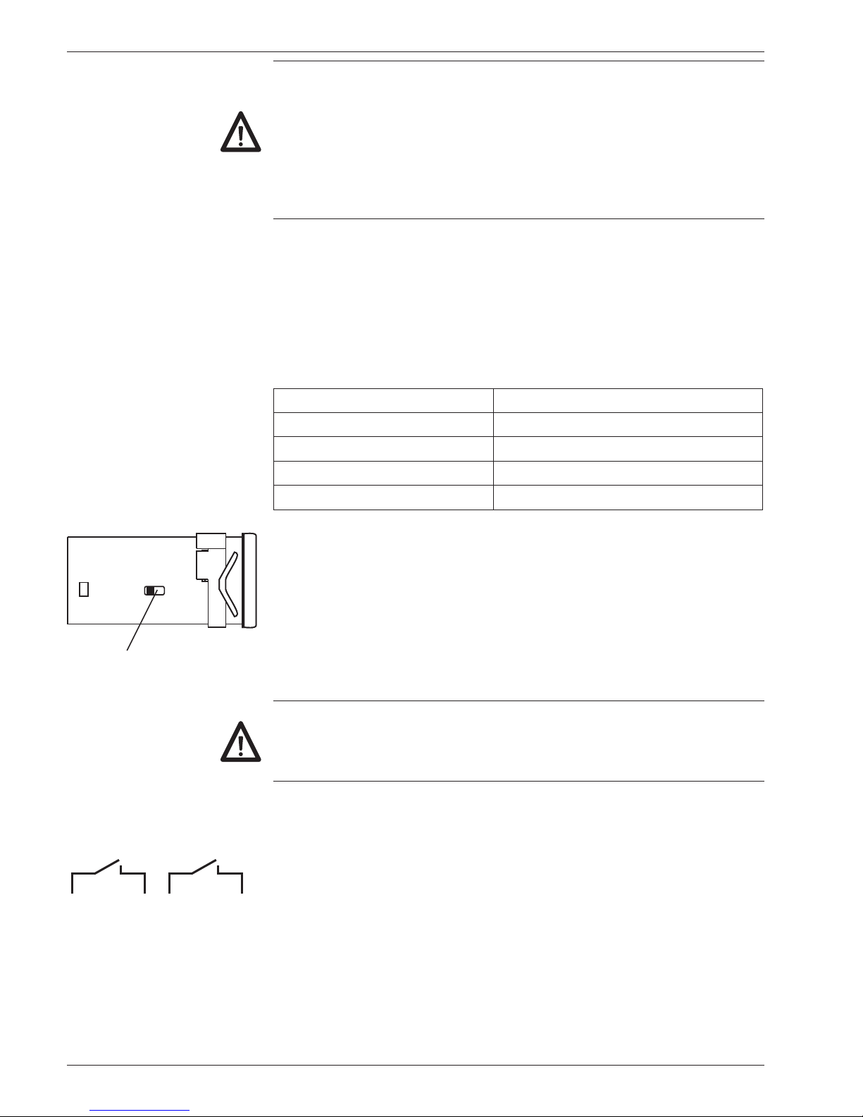
The user must take care that, in case of disturbance, the contact
rating of 8 A / 150 VA (W) is not exceeded. Internal spark suppressi-
on by means of zinc-oxide varistor (275 V). The output relays of the
instrument (1 relay or several) may in total switch 5 x per minute at
the most. Admissible clicks according to interference suppression
standard for the industrial sector. In case of higher switching rate,
the operator will be responsible to take care of local interference
suppression in consideration of the contact rating.
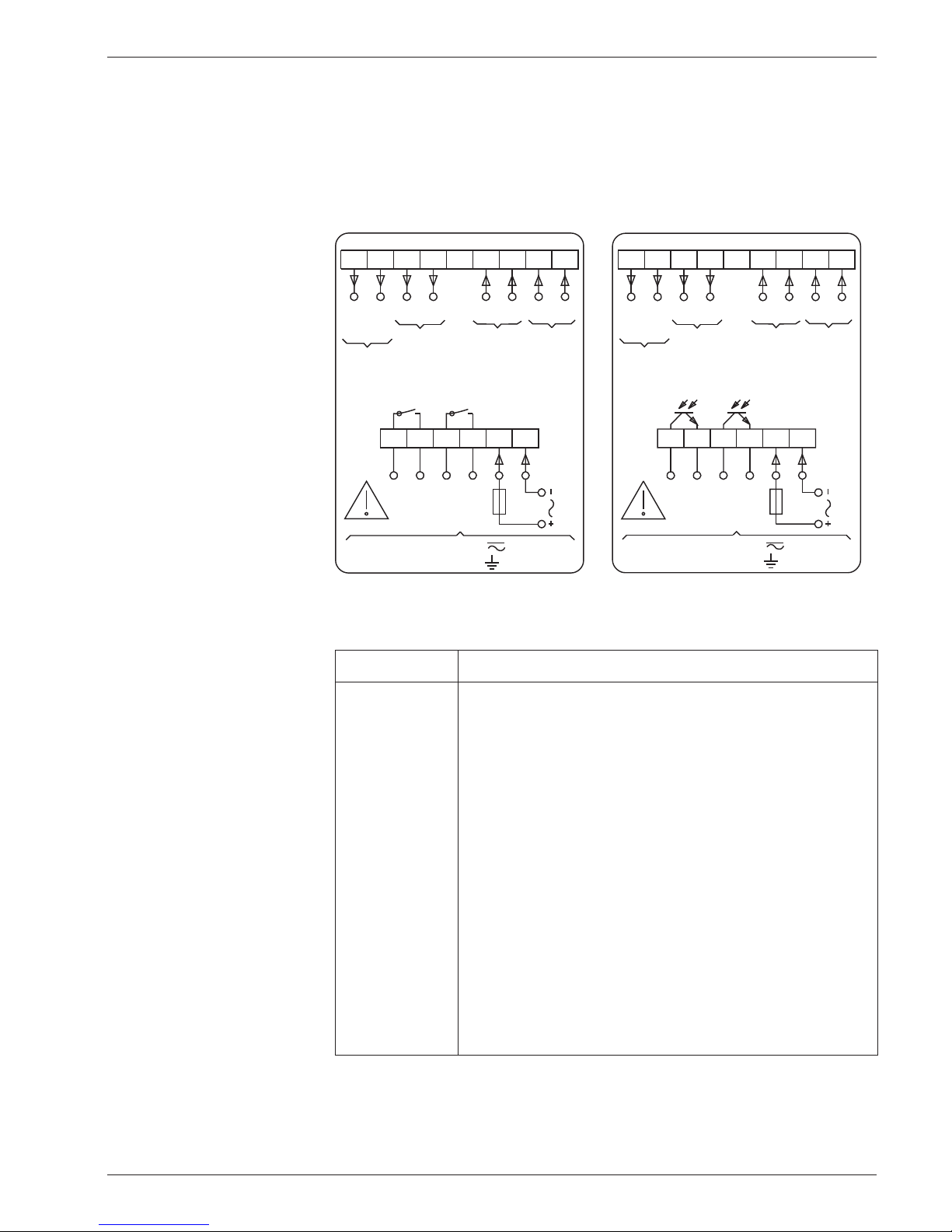
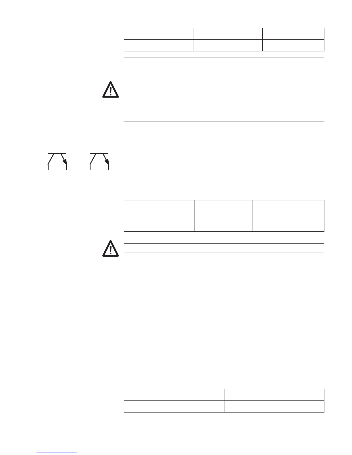
3.3 Assignment of signal outputs (electronic)
4 36 5
Output P2 Output P1 The electronic outputs (contacts 3, 4 and 5, 6) are optocoupler
outputs. The signal outputs can be assigned as per the adjacent
terminal diagram.
The type of output, as momentary or latched signal, can be chosen
in the programming lines 41/42.
Their function, as normally open or closed, is selected in program-
ming line 40.
Max. switching
voltage
Max. switching
current
Max. residual voltage
+40 VDC 25 mA at 25 mA <1 V
The electronic outputs are not short-circuit-proof.
3.4 Assignment of signal inputs
Choice of PNP or NPN The contacts 7 to 10 are comparator signal inputs.
They can be triggered either by PNP or NPN sensors. The input logic
as well as the operating threshold are correspondingly chosen in pro-
gramming line 33.
The contacts 7 (Track A) and 8 (Track B) are counting inputs for a
counting range between 3 Hz, 25 Hz or 10 kHz. The counting rate is
determined in programming lines 31 and 32.
The contacts 9 and 10 are 2 control inputs for Reset, Stop, Hold,
Print, Keylock etc. The function of these control inputs is selected in
the programming lines 34 and 36.
The minimum pulse duration of control input 1 can be switched in
programming line 35 from 30 ms to 100 s. For control input 2, 30
ms are generally valid.
Input resistance Selectable operating threshold
approx. 3 kΩ 3 V and 6 V

NE216
30 www.baumer.com
3.5 Examples of connection
Sensor Contact assignment Programming
Contact
7
12
Track A
+24 V
Counting rate:
Line 31 to 1 = 25 Hz
Line 31 to 2 = 3 Hz
Proximity switch PNP or NPN
7
12
13
Track A
+24 V
0 V
Input logic:
Line 33 to 0 = PNP
Line 33 to 1 = NPN
Namur without explosion protection
7
13
Track A
0 V
Input logic:
Line 33 to 1 = NPN
Incremental encoder
7
8
12
13
Track A
Track B
+24 V
0 V
Counting mode:
A 90° B (x1, x2, x4)
Line 30 to 3, 4, 5
Counting rate:
Line 31, 32 to 0 = 10 kHz
3.6 Connecting the sensor supply
Connect the sensor supply at terminals 12 and 13 – for example en-
coder supply, etc.
Do not use the sensor supply to supply non-earthed inductive or
capacitive loads. The sensor supply is short-circuit proof (exception
model 24/48 VAC).
Voltage supply Sensor supply Current load
24 VAC 10...26 VDC 60 mA
48 VAC 10...26 VDC 60 mA
85...265 VAC 24 VDC ±20 % 100 mA
12...30 VDC 9...28 VDC ±20 % 100 mA

NE216
www.baumer.com 31
3.7 Interface connection
The serial interface can perform the following functions:
- retrieve data
- program parameters
Interface parameters are:
- transmission speed (baud rate),
- parity bit,
- number of stop bits,
- address of controller for master.
The interface parameters can be set on the programming level (Lines
51, 52, 53 and 54).
RS485 Half-duplex transmission with the following features:
- symmetrical
- 2 lines
- multi-point connection – emitter and receiver (max. 32 units)
- maximum distance of data transmission:1500 m
«Assign contacts 14 (T,R-) and 15 (T,R+) accordingly.
4 Operating mode
The following chapter will inform you on the operation.
OThe counter is automatically on the operator level after the supply
voltage has been turned on.
On the operator level it is possible
- to read and, if necessary, clear the current count PC;
- to read and, if necessary, modify the presets P1 and P2;
- to read and, if necessary, modify the preset start count;
- to read and, if necessary, clear the totalizer;
- to read and, if necessary, modify the scaling factor.
It is possible to disable all operator parameters on the programming
mode (lines 11-17).
4.1 Key functions
Parameter reading The key allows to switch to the next operation parameter.
For quick sweep, keep the key depressed.
Resetting of counts 1.
Display count of respective parameter.
2. Press key.
Setting of parameters 1. Display parameter.
2. Press key and select required decade; chosen decade
position blinks.
3. Press key and enter required value.
To set further decades, repeat steps 2 and 3.
4. Confirm the parameter entered with . Should no confirmation
be given within 15 s, the previous setting will remain valid.

NE216
32 www.baumer.com
Clear
Current count
After the counter has been turned on or upon selection via , „C“
appears for one second on the display. The current count is then
displayed for reading.
«Read count PC.
«Press key.
Read
Modify
Preset P1
«Press key.
„P1“ appears for one second on the display. The preset P1 is
then displayed for reading.
«Enter preset P1 via and .
Press key.
Read
Modify
Preset P2
«Press key.
„P2“ appears for one second on the display. The preset P2 is
then displayed for reading.
«Enter preset P2 via and .
Press key.
Read
Modify
Start count SC
«Press key.
„SC“ appears for one second on the display. The display then
jumps to the current start count SC.
«Enter SC via and .
Press key.
Read
Totalizer tot
«Press key.
„tot“ appears for one second on the display. The display then
jumps to the current total.
I
f the value 99999 is exceeded, its display will be shown in two steps.
First step: Display of the first 5 digits.
Second step: marked by „H“, Display of 6th, 7th and 8th digits.
Display of each value for approx. 3 seconds
Clear «Press key.
Scaling factor SF
The scaling factor allows the display of fractions or multiples of the
counting pulses.
Setting range: 0.0001 to 999.99
Setting ex factory: 1.0000.
Example In the case of a length measurement by means of encoder and
cyclometer, where the circumference of the cyclometer measures
200 mm and the encoder supplies 500 pulses per revolution, the
measurement is to be displayed in mm.
The scaling factor is calculated as follows :
Scaling factor = Circumference =200 = 0.4000
Pulses 500

NE216
www.baumer.com 33
Read
Modify
«Press key.
„SF“ appears for one second on the display. The display then
jumps to the current scaling factor SF.
«Enter scaling factor SF via and .
The setting range from 0.0001 to 999.99 is attained by shifting
the decimal point. Select decimal point via and shift via .
«Press key.
By pushing again, the current count is re-displayed.
5 Programming mode
Operation parameters are set on the programming level.
The programming level consists of 3 programming fields.
Access is protected by a 4-digit code.
Programming field 1
Here it is possible to select and modify all operation parameters. The
operation parameters that are disabled for the operator are also dis-
played.
Programming field 2
The individual operation parameters for operator access are disabled
or enabled here.
Programming field 3
All functions and values as well as interface parameters conditioned
by the machinery are programmed here.
Switch on programming
«Press and key simultaneously.
„Code“ appears on the display.
No code number has yet been set at the factory, therefore it is
possible to skip the code query by pushing . The code is set on
programming line 50. After a code has been set, it will only be possi-
ble to switch to the programming level by entering the correct code.

NE216
34 www.baumer.com
Enter code
Enter code via
and keys
.
Press key to confirm.
T
he instrument switches from the operator to the programming level.
Wrong code If a wrong code has been entered, „Error“ is displayed as long as
remains pushed. After 15 s the instrument switches automatical-
ly back to the operator level.
Correct code unknown If the correct code is not known, please return the counter to the
supplier or effect reset to factory setting.
Select programming lines Select the required programming line via . Its corresponding line
number will be displayed.
For quick sweep, keep depressed.
Jump back to
programming line
By keeping depressed and by operating it is possible to jump
back within the programming lines.
Modify operation
parameters
Select the decade to be changed via .
The selected decade blinks.
Enter the value by pushing .
Press key to confirm.
Leave programming It is possible to shut down the programming at any time by pushing
and simultaneously (keep depressed for 2 seconds).
Reset to factory setting Turn on instrument and press and simultaneously. All values
already programmed are set back to the factory setting. „ClrPr“
appears on the display.
Programming field 1
Here it is possible to select and modify all operation parameters.
The operation parameters that are disabled for the operator are also
displayed.
Line 1 PC - Main counter (current count)
Line 2 P1 - Preset 1
Line 3 P2 - Preset 2
Line 4 SC - Start count
Line 5 tot - Totalizer
Line 7 SF - Scaling factor
The dash line indicates the end of the first programming field.
Switch to programming field 2 by pushing .

NE216
www.baumer.com 35
Programming field 2
The individual operation parameters for operator access are disabled
or enabled here.
O„Stat“ appears on the display. The denominations of the chosen
line „PC“, „P1“, „P2“, „tot“, „SC“ and „SF“ are displayed for one
second. Then the display jumps to StAt with the current status
value.
Meaning of the status numbers
0It is possible to select, read and modify the operation para-
meter on the operator level. (free access)
1It is possible to select and read the operation parameter on
the operator level. (display only)
2It is impossible to select the operation parameter on the
operator level. It is corresponding function is however
sustained. (disabled)
Modify status Enter corresponding status number via and
.
Modified status number is automatically memorized when the next
programming line is selected via .
Line 11
PC - Main counter
Line 12
P1 - Preset 1
Line 13
P2 - Preset 2
Line 14
SC - Start count
Line 15
tot - Totalizer
Line 17
SF - Scaling factor
The dash line indicates the end of the second programming field.
Switch to programming field 3 by pushing .

NE216
36 www.baumer.com
Programming field 3
All functions and values as well as interface parameters conditioned
by the machinery are programmed here.
Each factory setting is marked as such by *.
Line 21 Operating modes main counter
0 * Adding, final signal at P2, reset to SC
1 Subtracting, final signal at SC; if programming with automatic
reset (Line 23), it is effected at SC
2 Subtracting, final signal at SC; if programming with automatic
reset (Line 23), it is effected at 0.
Line 22 Preset mode
0 * Step preset
1 P1 - Trailing preset
Line 23 Reset modes
0 * With automatic reset
1 Without automatic reset
Line 24 Decimal point for PC, P1, P2, SC, tot
0 * No decimal point
1 0000.0
2 000.00
3 00.000
Line 30 Counting mode
0 * Counting input track A, reversal track B
1 Subtraction track A adding and track B subtracting (A-B)
2 Totaling track A adding and track B adding (A+B)
3 Track A 90° B single evaluation
4 Track A 90° B double evaluation
5 Track A 90° B quadruple evaluation
t
In case of the counting mode „Track A 90° B“, the frequency of
Track A and B, Line 31 and 32, has to be adjusted to 10 kHz.
6 Time meter with preset. Counting while track A active. Track B
has no function.
7 Time meter with preset. Counting started via track A and stop-
ped via track B. Track A and B edge-triggered.
tThe time range is selected in line 43.
Line 31 Frequency main counter track A
0 * 10 kHz
1 25 Hz
1 3 Hz
Line 32 Frequency main counter track B
0 * 10 kHz
1 25 Hz
2 3 Hz
Line 33 Input logic and operating threshold of signal inputs
0 * PNP Operating threshold 6 V
1
NPN Operating threshold 6 V, or for Namur without Ex. protection
2 PNP Operating threshold 3 V
3 NPN Operating threshold 3 V

NE216
www.baumer.com 37
Line 34 Function control input 1 (Contact 9 )
0 * PC - Main counter - Reset static
1 PC - Main counter - Reset edge-triggered
2 tot - Totalizer - Reset edge-triggered
3 Stop (PC - Main counter and tot - Totalizer)
4 Hold (PC - Main counter and tot - Totalizer)
5 Programming disabled
6 Keylock (preset change and programming disabled)
7 Print
8 Outputs ON
9 Outputs ON and PC principal counter - Reset edge-triggered
Line 35 Minimum pulse duration for control input 1
0 * 30 ms
1 100 µs
Line 36 Function control input 2 (Contact 10)
0 PC - Main counter - Reset static
1 PC - Main counter - Reset edge-triggered
2 tot - Totalizer - Reset edge-triggered
3 * Stop (PC - Main counter and tot - Totalizer)
4 Hold (PC - Main counter and tot - Totalizer)
5 Programming disabled
6 Keylock (Preset change and programming disabled)
7 Print
8 Outputs OFF
Line 38 Take-over of presets P1, P2, SC
0 * Effective immediately
1 When resetting
Line 40 Output logic
0 * Both outputs as normally open
1 P1 normally closed, P2 normally open
2 P1 normally open, P2 normally closed
3 Both outputs as normally closed
Line 41 Output time P1
0,01 s Minimum signal duration
* 0,25 s
99,99 s Maximum signal duration
LAtCH = Latched signal (by pressing the key)
Line 42 Output time P2
0,01 s Minimum signal duration
* 0,25 s
99,99 s Maximum signal duration
LAtCH = Latched signal (by pressing the key)
Line 43 Time range hour counter
0 * 999 s 99/100 s
1 99 min 59 s 9/10 s
2 999 min 59 s
3 999 h 59 min

NE216
38 www.baumer.com
Line 44 Rapid preset recognition
0 * Standard preset recognition
1 Rapid preset recognition P2, delay period min. 30 s,
max. 60 s. Only in case of adding operation mode,
Line 21 = 0, and counting mode 0, 3, 4, 5, under line 30.
Line 50 Code settings
0 * Code not active
Max. 9999
Line 51 Baud rate
0 * 4800 Baud
1 2400 Baud
2 1200 Baud
3 600 Baud
The programming lines 51-54 are
only displayed for models with
interface
Line 52 Parity
0 * Even parity (7 data bits)
1 Odd parity (7 data bits)
2 No parity (8 data bits)
Line 53 Stop bits
0 * 1 Stop bit
1 2 Stop bits
Line 54 Address
0 * from
99 to
The dash line indicates the end of the third programming field.
As soon as pushed again, the instrument will automatically
return to the operator level. Programming can, however, be shut
down on any line by simultaneously pushing and (keeping
the keys depressed for approx. 2 seconds).
5.1 Operating and preset modes
The following paragraphs describe the operating modes.
Step preset The counter counts to the next preset after having reached a preset.
The preset are always handled in the sequence P1, P2. You can se-
lect the preset of your choice.
An automatic reset to 0 and/or to the start count SC is possible at
P2 (at the second preset). An external or manual reset is possible at
any time.
P1- trailing preset The entry of preset P1 corresponds to the interval between the
previous signal and the final signal. This means that when changing
the final signal, i.e. the preset P2, the previous signal will be auto-
matically adjusted or „trailed“. This mode is well suited for switching
between rapid and creeping speed in the case of length measure-
ment applications.

NE216
www.baumer.com 39
5.2 Counting modes for main counter and totalizer (input mode)
Counting input track A,
Reversal track B (Up/
Down)
The adding and/or subtrac-
ting counting directions are
automatically set when se-
lecting the operating mode
in programming line 21
(diagram for adding mode).
If necessary, it is possible
to use the entry track B for
reversal of direction count.
Programming line 30 to
digit 0.
7UDFN$
8S'RZQ
&RXQWLQJ
Differential counting,
track A adding and track
B subtracting (A-B)
Signal duration and particu-
lar time at choice.
Programming line 30 to
digit 1.
7UDFN$
7UDFN%
&RXQWLQJ
Totaling track A adding
and track B adding (A+B)
The adding and/or subtrac-
ting count directions are
automatically set when se-
lecting the operating mode
in programming line 21.
Programming line 30 to
digit 2.
7UDFN$
7UDFN%
&RXQWLQJ
$GG
Up and down count with
two counting signals by
90° out of phase
The counting direction is
automatically recognized
on the basis of the 90°
leading or trailing phase
shift. The internal phase
discriminator does the
evaluation. Single, double
or quadruple evaluation is
possible.
Programming line 30 to
digits 3, 4 or 5.
7UDFN$
7UDFN%
&RXQWLQJ
[
&RXQWLQJ
[
&RXQWLQJ
[

NE216
40 www.baumer.com
5.3 Output (output mode)
The behaviour of the signal outputs is defined by the following set-
tings under the programming field 3: Operating mode, preset mode,
reset mode, take-over of presets, output logic and output time P1,
P2 as momentary or latched signal .
The following diagrams illustrate some examples:
Programming Operating mode
Line 21 to 0 = adding
Operating mode
Line 21 to 1 = subtracting
Preset mode:
Line 22 to 0 = Step preset
Reset mode:
Line 23 to 1
without automatic reset
Output time P1, P2:
Line 41, 42 to pulse or
duration
5(6(7
9:3
9:3
6&
2873
2873
5(6(7
6&
9:3
9:3
2873
2873
Preset mode:
Line 22 to 0 = Step preset
Reset mode: Line 23 to 0
with automatic reset
5(6(7
9:3
9:3
6&
2873
2873
5(6(7
6&
9:3
9:3
2873
2873
Preset mode:
Line 22 to 1 = Trailing preset
VW (P1) corresponds to the
interval between P1 and P2.
When P2 is changed, P1 is
trailed.
5(6(7
9:3
6&
2873
2873
9:3
Operation mode:
Line 21 to 2 = OUT P2 at SC,
automatic reset at 0
Preset mode:
Line 22 to 0 = Step preset
5(6(7
6&
9:3
9:3
2873
2873
Preset mode:
Line 22 to 0 = Step preset
Reset mode: Line 23 to 1
without automatic reset
Function control input 1:
Line 34 to 9
OUT P1 and OUT P2 are
activated by a signal to
control input 1 (Ein St1) and
the count is reset.
9:3
6&
2873
2873
5(6(7
9:3
6&
9:3
2873
2873
5(6(7
9:3

NE216
www.baumer.com 41
6 Technical data
Technical data - electrical ratings
Voltage supply 24/48 VAC ±10 % (50/60 Hz)
85...265 VAC (50/60 Hz)
12...30 VDC, 5 % RW
Power consumption 5 VA, 5 W
Sensor supply 24/48 VAC: 10...26 VDC / 60 mA
85...265 VAC: 24 VDC ±20 % / 100 mA
12...30 VDC: 9...28 VDC / 100 mA
Display LED, 7-segment display
Number of digits 5-digits
Digit height 7.6 mm
Function Preset counter
Main counter with 2 presets
Totalizer
Hour counter
Scaling factor 0.0001...9999.99
Count modes Adding or subtracting
A-B (difference counting)
A+B total (parallel counting)
Up/Down
A 90° B phase evaluation
Counting frequency 3 Hz, 25 Hz, 10 kHz programmable
Operating modes Step preset, Trailing preset,
Time meter and hour counter
Data memory >10 years in EEPROM
Reset Button, electric or automatic
Outputs electronic Optocoupler
Outputs relay
Normally open or closed, programmable
Output holding time 0.01...99.99 s
Interface RS485
Standard Protection class II
DIN EN 61010-1 Overvoltage category II
Pollution degree 2
Emitted interference DIN EN 61000-6-4
Interference immunity DIN EN 61000-6-2
Programmable Operating modes
parameters Sensor logic
Scaling factor
Count mode
Control inputs
Approval UL approval / E63076

NE216
42 www.baumer.com
Technical data - mechanical design
Ambient temperature 0...+50 °C
Storing temperature -20...+70 °C
Relative humidity 80 % non-condensing
E-connection Plug-in screw terminals
Core cross-section 1.5 mm²
Protection DIN EN 60529 IP 65 face with seal
Operation / keypad Membrane with softkeys
Housing type Built-in housing
Dimensions W x H x L 48 x 48 x 100 mm
Installation depth 100 mm
Mounting Clip frame
Cutout dimensions 45 x 45 mm (+0.6)
Materials Housing: Makrolon 6485 (PC)
Keypad: Polyester
Weight approx. 150 g (12...30 VDC / 85...265 VAC)
260 g (24/48 VAC)
Technical data - trigger level
Comparator inputs Input circuit
Inputs PNP- / NPN-logic
Input level Programmable
Input level Low 0...2 VDC
Input level High 3...40 VDC
Input resistance 3 k
Relay outputs Output circuit
Switching voltage max. 250 VAC / 110 VDC
Switching current max. 1 A
Switching capacity max. 150 VA / 30 W
Relay responding time 5 ms
Electronical outputs Output circuit
Optocoupler short-circuit proof
Switching voltage max. 40 V
Switching current max. 25 mA
Residual voltage <1 V
Table of contents
Other Baumer Cash Counter manuals

Baumer
Baumer NE212 User manual

Baumer
Baumer Scatec-10 User manual

Baumer
Baumer IO-Link Master User manual

Baumer
Baumer ISI Series User manual

Baumer
Baumer NE215 User manual

Baumer
Baumer NE134 User manual

Baumer
Baumer FLDK 110G1003/S14 User manual

Baumer
Baumer NE214 User manual

Baumer
Baumer NE230 User manual

Baumer
Baumer ME102 User manual
Popular Cash Counter manuals by other brands

TSI Instruments
TSI Instruments 3022A instruction manual

Fraud Fighter
Fraud Fighter FF-3000 operating manual

Labelmate
Labelmate RRC-400 user manual

Triton
Triton FT5000 Service manual

Nautilus Hyosung
Nautilus Hyosung MONiMAX7600DA Operator's manual

Carrera
Carrera Digital 124 Wireless+ Assembly and operating instructions