Baxi MULTIFIT Flue Systems Assembly instructions

© Baxi Heating UK Ltd 2011
GUIDANCE NOTES
Flue Accessories & Fitting Guide
Ø 60/100 Flue Systems
Ø 80/125 Flue Systems
Ø 80/80 Twin Flue Systems
Plume Displacement Kit (Ø 60/100 Flue Systems)
READ THESE INSTRUCTIONS IN CONJUNCTION WITH THE BOILER
INSTALLATION INSTRUCTIONS BEFORE FITTING THE FLUE
Please leave these instructions with the
Installation & Servicing Instructions.
IMPORTANT NOTE: This document
will assist in the correct installation of
the various flue & chimney systems
described within. However, it is the
responsibility of the installer/Gas Safe
registered commissioning engineer to
ensure that the flue & chimney system
is fitted safely and in compliance with
the relevant standards and practices in
force in the country of installation.

page 2
© Baxi Heating UK Ltd 2011
• Flue systems must be constructed using only components
approved for use with the appliance and installed in
accordance with BS 5440 Part 1, any manufacturers
instructions and Part J of the Building Regulations.
• In order to meet the requirements of the Gas Safety (Installation
& Use) Regulations, provision should be made such that all flue
joints and supports can be inspected.
• The flue system should have a continuous fall back to the boiler
(1.5° to 3°) and be supported at least once every metre using
suitable support brackets (where shorter straight lengths are used,
for example between two bends, these should also be
supported).
• Ensure that the there are no ‘dips’ in the flue system.
• Consideration must be given to protect exposed parts of the
outlet duct where accidental touch may occur.
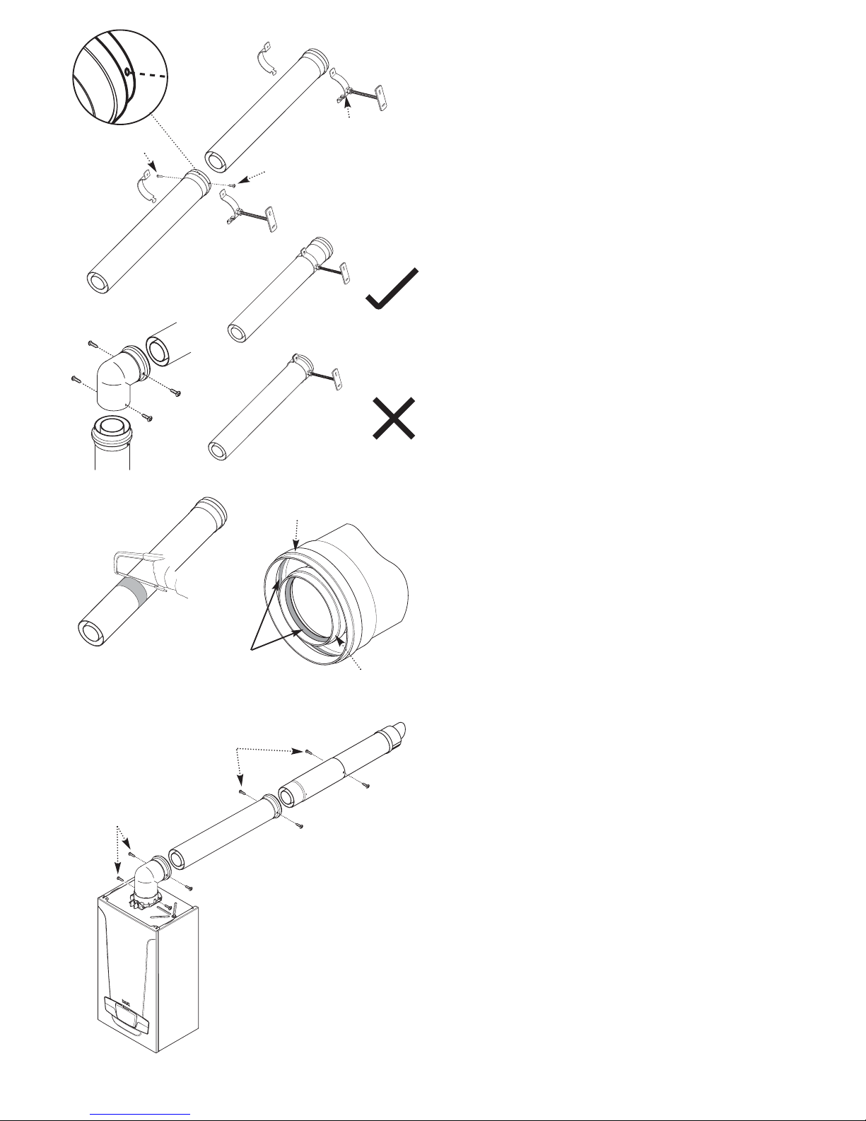
• All fittings should be correctly engaged and secured where
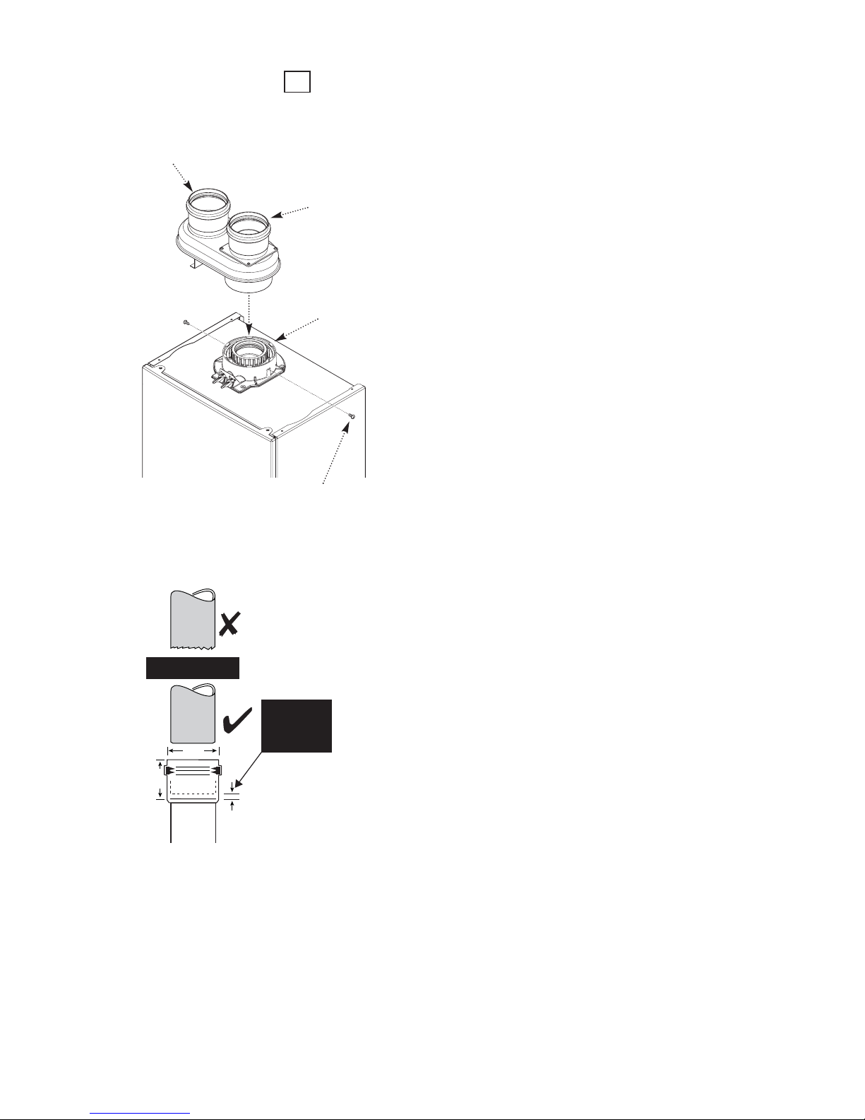
necessary. Expansion Gap details must be observed on twin
pipe 80/80 systems (Flue Group N).
• Flue extensions can be cut to length if necessary. The cut end
should be square and de-burred to prevent damage to seals when
assembling to a fitting.
• The MAXIMUM total equivalent length is given in the boiler
Installation & Servicing Instructions.
• If the flue system is to be fitted prior to the boiler, temporary
precautions must be taken to prevent rain entry into the room of
installation. Any precautionary measures must be removed prior
to fitting the boiler.
• It is the responsibility of the installer to ensure the integrity of
the flue & chimney system before commissioning the boiler.
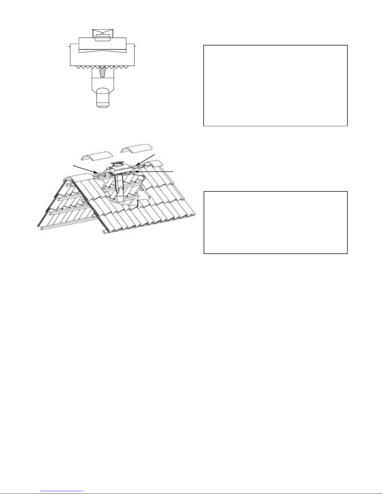
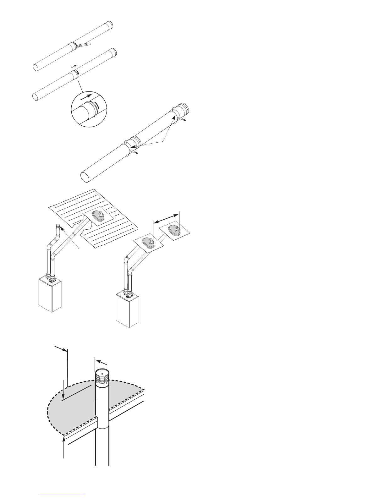
FLUE TERMINATIONS
It is important to protect building structures from the condensate
plume produced from the boiler exhaust duct flue terminal. This
should always be directed away, by using plume deflector or PDK
if necessary. Where PDK’s terminate under balconies it is
recommended to extend the terminal beyond the balcony.
TERMINAL GUARDS
• It is necessary to use a Terminal Guard where there exists the
risk of blockage and/or damage to the terminal or air intake of the
PDK, and also in instances where there is a risk of injury to people,
including the possibility of exposure to high temperatures.
• Any terminal that is less than 2 metres above finished floor or
ground level must be guarded. This also applies when terminals
are positioned above flat roofs and balconies to which there is
regular unimpeded access.
• A guard must not prevent correct & safe operation of the
appliance the terminal is connected to.
IMPORTANT NOTES
Please read before continuing with the flue installation !
CHIMNEYS & FLUES IN VOIDS
“Voids” includes ceiling & floor voids, purpose-built enclosures,
service risers, certain types of roof space and any other enclosure
that restricts access to the chimney.
The need to inspect applies to concentric and twin systems, and
both the air and flue ducts of the latter.
The requirement to inspect does not apply where a boiler is
mounted on the wall and the chimney system runs within the
building structure (e.g. direct from the rear of the boiler through
the wall to outside).
A proprietary liner containing a chimney system is also exempt,
providing there are no joints in this part of the system.
B.S. 5440-1, Gas Safety (Installation & Use) Regulations and any
Gas Safe Register Technical Bulletins must be consulted.
Chimney systems must not pass through other properties
because access may not always be available for inspection.
Access must be provided at strategic locations to allow
inspection to confirm:-
i) the system is continuous
ii) all joints are correctly assembled & sealed
iii) adequate support has been provided
iv) any “fall” or drain point required for condensation
has been provided
Inspection hatches must be permanent, be of sufficient size and
number, located such that no special equipment (e.g. an
endoscope) is required to perform inspection and have suitable
fire resistance.
Inspection hatches must comply with the following:-
i) all voids containing a concealed chimney system must
have at least one hatch
ii) hatches must be at least 300mm x 300mm
iii) no joint in the flue must further than 1.5m from the
edge of the nearest hatch
iv) hatches should, where possible, be located at
changes of direction in the flue
v) where iv) is not possible bends should fully visible
from both directions
As far as practicable hatches should be installed in non-habitable
areas such as cupboards and passageways.
A Gas Safe Registered engineer should always be consulted when
considering the positioning of inspection hatches.
The presence of other services and pipework may influence the
location of inspection hatches. In exceptional circumstances these
other services may have to be re-routed to allow suitable
positioning of a hatch.
Installation of any hatch shall not compromise the integrity and
safety of the property. If necessary consult Local Building
Regulations or Building Control Office for guidance. In all
instances the hatch manufacturers instructions should be
consulted and adhered to.
FIRESTOPS
Use of firestops may be required where the flue or chimney
passes between rooms or spaces. Any firestop or collar MUST
NOT prevent the linear expansion or contraction of the flue or
chimney
MAKING GOOD
Where the flue system passes through an external wall the joint
should ‘made good’ by use of suitable sealant or building
materials and the flue trims supplied if required.
Terminal Guard
Part No. 720627901

page 3
© Baxi Heating UK Ltd 2011
AB
K, K1
R
D
C
N
U
S
L
H
J
M
FLUE ACCESSORIES Flue Groups
Ø60/100 Flue Systems - with Positive Fix
Ø80/125 Flue Systems
Ø80/80 Twin Flue Systems
E
GF
A4
G
N
A
Y, Z
Key Accessory Size Code No
FLUE GROUP A
Concentric Flue System 60/100mm diameter
A Telescopic Flue (Black) 315-500mm 720598701
A Telescopic Flue (Brown) 315-500mm 720642701
A Telescopic Flue (White) 315-500mm 720599401
A Telescopic Flue Neta-tec &
Platinum GA (Black) 315-500mm 720870201
(all Telescopic Flues include 1 x Low Profile Bend)
B Flue Extension (includes support bracket) 1000mm 720648801
B Flue Extension (includes support bracket) 500mm 720643001
B Flue Extension (includes support bracket) 250mm 720643101
C Flue Bend (In Line) 93° 720648401
C2 Offset Elbow (for boiler only, Duo-tec 93° 720635501
range & Megaflo 32 )
D Flue Bend 135° 720648501
D Flue Bend (pair) 135° 720647901
U Flue Support Bracket 100mmØ 5111080
R Vertical Flue Adaptor 60/100 to 80/125
(use with 5111078) 5111070
S Flue Terminal Deflector (Black) 5111068
S Flue Terminal Deflector (White) 720644201
S Flue Terminal Deflector (Brown) 720642701
MISCELLANEOUS
Z Single Terminal 80mm (air inlet only) 5121791
Z1 60 - 80 Adaptor - Twin Flue 5121792
Z2 Pitched Roof Terminal-Twin Flue (Z1 req’d) (Black) 720576301
Z3 Ridge Terminal (Brown) 720647101
Z4 PDK - (Black) 720622901
Z4 PDK - (White) 720627001
Key Accessory Size Code No
FLUE GROUP G
Flue System 80/125mm diameter
A4 Horizontal Flue Kit 685mm 5118580
B Flue Extension Kit 1000mm 5118584
DBend
(pair) 135° 5118597
C Bend 91.5° 5118588
U Flue Support Bracket 125mmØ 5118610
FLUE GROUP N
Twin Flue System 80mm diameter
E Flue Extension (pair, includes 2 brackets) 1000mm 5111087
F Flue Bend (pair) 90° 5111072
G Flue Bend (2 pair) 135° 5111086
J Vertical Flue Boiler Adaptor Kit 5111079
H Vertical Flue Adaptor 5111084
Y Twin Flue Terminal (Horizontal Termination) 5120172
W Flue Support Bracket (pair) 80mmØ 5111081
FLUE GROUP A, N, G
Vertical Flue Kits
K Vertical Flue Terminal 60/100 5118576
K1 Vertical Flue Terminal 80/125 (Black) (use with 5111070) 5111078
L Pitch Roof Flashing (Black) 25°/50° 5122151
M Roof Cover Plate 246143
N Flat Roof Flashing (Black/Grey) 246144
Z1
Z4
Z3
Z2
C2
W
x4 x2

page 4
© Baxi Heating UK Ltd 2011
CONCENTRIC FLUE SYSTEM (60/100) ONLY - FLUE GROUP A
USE OF SUPPORTS & SECURING
Each extension and securing screws (1m, 500mm & 250mm) is
supplied with a support bracket. Additional support brackets can be
purchased separately (see Flue Accessory page overleaf). DO NOT
use brackets other than those supplied or shown in this guide.
The flue system MUST be supported AT LEAST once every metre
of actual length, and every straight length should be supported with
a bracket.
The bracket should be positioned as close to the female end of the
extension providing that the surface the bracket is to be fixed to is
sound. DO NOT position the bracket over the swaged part of the
extension or the rivets.
Also provided with each extension and elbow are two special self
drilling screws. These MUST be used to secure the female air duct
to the male duct of the next extension or elbow (in exceptional
circumstances were access is limited one screw will suffice).
CUTTING EXTENSIONS
Where it is necessary to reduce the length of an extension, both
exhaust and air duct MUST be cut square and flush, and any burrs
removed to avoid damage to the flue seal on both exhaust and air
duct on assembly.
It is recommended that tape is used as a guide to first cut around
the air duct and then the exhaust duct be cut square and flush with
the air duct.
The spring support should be positioned approximately 100mm
from the male end of the extension to maintain concentricity.
ASSEMBLING
Both ducts of the elbow or extension are fitted with an inner lip
seal. It is important that the seals are lubricated as follows:-
Use suitable gloves - open the sachet of grease supplied and apply
grease sparingly to the inner seal of both air and exhaust ducts to
aid assembly.
Wipe away any excess grease prior to assembly. Avoid contact with
eyes after handling the grease, and thoroughly wash hands.
Engage the male end of the extension or elbow into the female of
the next extension or elbow. Ensure that it is fully inserted to
achieve the required penetration depth. The extension have been
designed to maintain an expansion gap for the exhaust duct.
Using the special self drilling screws supplied secure the air duct to
the next extension or elbow. The screws must be inserted via the
holes in the female end of the air duct or through the indentations
on elbows/bends. NOTE: No drilling is required - the screw will
pierce the male end of the extension or elbow.
Identify the positions of the support brackets and mark the wall or
surface on which they will be mounted. Drill and plug as required.
If necessary shorten the threaded rod. Fix the support bracket to
the wall. Locate the tongue of the outer bracket half in the slot of
the inner half. When all brackets are in place offer the flue up to
them, and secure the two halves of the brackets with the screw. If
the rods are not long enough it may be necessary to erect a spacer
or structure to adequately support flue system brackets. It is not
recommended to use longer threaded rods.
IMPORTANT: Mounting and securing the flue will be easier if
performed by two people ! When the flue system is in place fully
tighten all brackets systematically, ensuring that no parts are under
any strain or tension and no dips where condensate can pool.
Silicone grease to
be applied to both
seals to aid fitting
Securing Screw
Securing Screw
Air Duct
Exhaust Duct
Securing Screws
Securing Screws
Support Bracket

page 5
© Baxi Heating UK Ltd 2011
Y
X
NOTE: Horizontal flue pipes should always be installed with a 1.5° to 3°
fall from the terminal to allow condensate to run back to the boiler.
Push the flue deflector over the terminal end and rotate to the
optimum angle for deflecting plume. Secure the deflector to the
terminal with screw provided.
Do not direct the deflector upwards or downwards.
NOTE: A terminal guard is still required when circumstances
dictate (B.S. 5440-1).
FLUE OPTIONS Horizontal Flue System Examples
Z
Y
This bend is equivalent to
1 metre
For Ø60/100 Flue Systems
Total equivalent length =
A+B+C+2x90°Bends
B
AC
This bend is equivalent to
1 metre
DO NOT DIRECT THE FLUE DEFLECTOR TOWARDS A WALL.
Flue Terminal
Flue Deflector
The MAXIMUM total equivalent length
is stated in the Installation & Servicing
Instructions supplied with each boiler.
N
I
I
G
F
M
I
AAF
H
J,K
D
E
H
Likely flue positions requiring
a flue terminal guard
C
L
B
Terminal Position with Minimum Distance (mm)
A1Directly below an opening, air brick, opening
windows, etc. 300
B1Above an opening, air brick, opening window etc. 300
C1Horizontally to an opening, air brick, opening window etc. 300
D2Below gutters, soil pipes or drain pipes. 25
E2Below eaves. 25
F2Below balconies or car port roof. 25
G2From a vertical drain pipe or soil pipe. 25
H2From an internal or external corner. 25
I Above ground, roof or balcony level. 300
J From a surface or boundary line facing a terminal. 600
K From a terminal facing a terminal (Horizontal flue). 1200
From a terminal facing a terminal (Vertical flue). 600
L From an opening in carport (e.g. door, window)
into the dwelling. 1200
1In addition, the terminal should be no nearer than 150 mm to an
opening in the building fabric formed for the purpose of accommodating a
built-in element such as a window frame.
2Only ONE 25mm clearance is allowed per installation. If one of the
dimensions D, E, F, G or H is 25mm then the remainder MUST be as
B.S.5440-1.
300 min
Terminal
Assembly
Top View Rear Flue
Property Boundary Line
NOTE: The distance from a fanned draught appliance terminal
installed parallel to a boundary may not be less than 300mm in
accordance with the diagram below
*
* Reduction to the boundary is possible down to 25mm but flue deflector
part no. 5111068 must be used.

page 6
© Baxi Heating UK Ltd 2011
Y
X
Y
X
Y
X
C 0.5m
Total Equivalent
Length
Roof
Terminal
Roof
Terminal
A 1m
B 1m C 0.4m
Roof
Terminal
A 0.7m
B 0.3m
This bend is equivalent to
1 metre
Total Equivalent Length =
A+B+C+1x90°Bend
All vertical and angled runs must be included,
measured from the boiler adaptor (point X) to the
joint with the flue terminal (point Y). One 93° bend
or two 135° bends can be included without
reduction of the flue length.
If further bends are required the flue
length must be reduced by the following
amounts:-
1 metre for each 93° bend
0.5 metre for each 135° bend
The MAXIMUM total
equivalent length is stated in
the Installation & Servicing
Instructions supplied with each
boiler.
X
Y
extensions
135°bend
93°bend
Actual Length
0.5m
1m
3 (A+B+C)
2*
0
1.4m
0
0
CONCENTRIC FLUE
Noof
fittings/pipes
Sub total
Equivalent
Length Value
Equivalent Flue Length = 1.4m
*Up to 2 x 135°bends are allowed without
affecting the calculation
extensions
135°bend
93°bend
Actual Length
0.5m
1m
3 (A+B+C)
0
2*
2.5m
0
1m
CONCENTRIC FLUE
Noof
fittings/pipes
Sub total
Equivalent
Length Value
Equivalent Flue Length = 3.5m
*1 x 93°bends are allowed without affecting the
calculation
Boiler Adaptor
80/125 Adaptor
Securing Screw
For Use With Flue Group
Ø80/125 Flue Systems
Ø80/125 FLUE SYSTEMS
The adaptor shown is available separately for
vertical flue applications. (It is included with
the 80/125 Horizontal Flue Kit).
Apply lubrication and ensure that the 80/125
adaptor is fully engaged in the boiler adaptor.
Secure with the screws supplied with boiler.
G

page 7
© Baxi Heating UK Ltd 2011
Fixing Tie
Fixing Tie
Ridge Line
Ridge Flue Terminal - Suitable for Flue Group A (60/100)
The MAXIMUM equivalent flue length when using this
terminal is 8 metres !
Special Notes
This flue terminal is designed predominantly for use in new
build situations where the roof construction allows for
ridge penetration.
In retrofit installations roofing materials will need to be
removed/replaced and the roof structure may require
alterations to accommodate the passage of the flue system.
Any work of this nature should be carried out by a
competent person and the integrity of the roof structure
should never be compromised.
The Ridge Flue Terminal replaces a 450mm ridge tile. The
profile allows it to blend with most common ridge tiles.
Positioning at the ridge should be in accordance with relevant
Building Regulations and British Standards. Ensure the roof is
prepared to allow for the throat section of the terminal
(50mm) to pass directly into the roof space and cut roofing
felt/boarding as necessary. A clearance of 25mm from
combustible materials must be maintained.
NOTE: Once installed the terminal design will allow rain
and condense to be discharged into the flue exhaust pipe.
It is essential to connect the ridge terminal to a
completed flue system connected to the boiler. If left
unconnected prior to the completion of fitting the flue
system and boiler, provision should be made to collect
rain water etc. from the terminal and to drain it away as
necessary.
Please Refer to the Fitting Instructions supplied with the Kit.
Ridge Terminal Assembly

page 8
© Baxi Heating UK Ltd 2011
Twin Pipe Flue System Examples
FLUE OPTIONS
The MAXIMUM total
equivalent length is stated
in the Installation &
Servicing Instructions
supplied with
each boiler.
1m Min
to
15m Max
The total equivalent
length for this example
is = 6.5 metres.
1m extension
135°bend
91.5°bend
1m
0.25m
0.5m
5
2
2
5.0m
0.5m
1.0m
AIR DUCT
Noof
fittings/pipes
Sub total
Equivalent
Length Value
Equivalent Length Air Duct = 6.5m
1m extension
135°bend
91.5°bend
1m
0.25m
0.5m
5
2
2
5.0m
0.5m
1.0m
EXHAUST DUCT
Noof
fittings/pipes
Sub total
Equivalent
Length Value
Equivalent Length Exhaust Duct = 6.5m
View
of
Outside
Wall
Fixed Flue
Terminal position
Exhaust
Possible Air Terminal positions
Air
AirAir
Mini Terminal Clearances
Flue
Clearance
Zone
Exhaust
Air
Air Air
Air Exclusion
Zone
Terminal Position - Separate Twin
1. Both terminals must be on the same wall. It is also permissible to situate
the air inlet terminal in a ventilated uninhabited void or compartment (e.g.
loft space)
2.The terminals must not be closer than 120mm when measured between
the centrelines (Fig. A).
3. If this distance is up to 300mm the flue outlet duct must protrude
200mm from the wall face. The air inlet must protrude 60mm (Fig. A).
4. When the distance between centrelines is greater than 300mm the flue
outlet duct must protrude 100mm and the air inlet 60mm (Fig. B).
5. When the air inlet terminal is situated in a ventilated uninhabited void or
compartment there must be at least 300mm from the floor of this space
to the terminal. No obstructions must be placed within a 300mm radius of
the terminal.
60mm
200mm
120mm to
300mm
60mm
100mm
Air Duct
Exhaust Duct
Air Duct
Exhaust Duct
Fig. A
Greater than
300mm
Fig. B

page 9
© Baxi Heating UK Ltd 2011
Exhaust Duct Adaptor
Air Duct Adaptor
FITTING THE ADAPTOR
For Use With Flue Group
Ø80/80 Twin Flue Systems
N
Boiler Adaptor
Twin Pipe Flue System (80/80)
The kit allows connection of a twin flue system to the boiler
adaptor.
Engage the twin flue duct adaptor in the boiler adaptor,
making sure that it is pushed down as far as possible.
Ensure that the air & flue ducts are connected correctly and
that they are adequately supported (at least once every
metre using the brackets supplied).
Cut the extensions to length if required (cut at the MALE
end !), ensuring that they are square and free from burrs.
USE OF SUPPORTS & SECURING
The flue system MUST be supported AT LEAST once every
metre of actual length, and every straight length should be
supported with the bracket supplied.
Additional support brackets may be purchased separately.
DO NOT use brackets other than those supplied or shown
in this guide.
The support bracket must be positioned on the main length
of the pipe.
Securing Screw
50mm
depth
Twin Flue Extension/
Bend Connection
Clean
Cut
Flue Pipe
Do Not Damage Internal Seals
with badly cut extensions
Badly
Cut
Flue Pipe
Ø80
Seal
Leave 5mm
clearance at
bottom of
each joint

page 10
© Baxi Heating UK Ltd 2011
ASSEMBLING
Engage the male end of the extension or elbow into the female of
the next extension or elbow. Ensure that it is inserted as shown
opposite to allow for expansion & contraction.
Identify the positions of the support clamps and mark the wall or
surface on which they will be mounted. Drill and plug as required.
When all brackets are in place offer the flue up to them, and
secure the two halves of the bracket with the screw.
IMPORTANT: Mounting and securing the flue will be easier if
performed by two people !
When the flue system is in place fully tighten all brackets
systematically, ensuring that no parts are under any strain or
tension.
TWIN PIPE SYSTEM - AIR INLET IN LOFT SPACE
VENTILATION & CLEARANCE
The air duct inlet terminal must be positioned in a suitably
ventilated loft space or compartment. The loft space or
compartment must not be a habitable room, and must be
ventilated ONLY to outside air.
The ventilation provided must be PERMANENT and not subject
to inadvertent blockage.
The loft space or compartment must be isolated from any
habitable area.
There must be a minimum of 300mm from the loft space or
compartment floor to the lower edge of the air inlet grille to
prevent accidental blockage. No obstruction must be placed
horizontally within 300mm of the air inlet.
Twin Pipe
System with Air
Duct Inlet in
Loft Space
300mm Clearance*
* The clearance around the air
inlet must extend 300mm in all
directions.
300mm
minimum
Support
Brackets
Air Inlet Terminal 5121791
MUST be in a suitably
ventilated loft space or
compartment, NOT
outside !!
600mm
Pull Extension back
5mm to allow for
expansion
Fully engaged
mark extension

page 11
© Baxi Heating UK Ltd 2011
R
J,K
S
T
U
Special Requirements for Vertical Balanced Flue
POSITION SPACING MIN
J From a surface or boundary line facing a terminal 600mm
K From a terminal facing a terminal 600mm
R From adjacent wall to flue 300mm
S From an adjacent opening window 1000mm
T Adjacent to windows or openings on pitched roofs 600mm
U Below windows or openings on pitched roofs 2000mm
Fitting the Roof Terminal to the Flashing:
Ensure the roof terminal collar is correctly seated onto the
flashing spigot to prevent leakage.
FITTING THE ROOF TERMINAL
Flashing
Spigot
Collar
Collar
Flashing
Spigot
Roof Terminal
Adaptor
Flue Terminal
Ø 80 Air Duct Ø Exhaust Flue Duct
(part of Flue Terminal)
xy
It is necessary to cut the flue terminal
air duct by 170mm. Dimensions x & y
must be 60mm.
For Roof Terminals
1. In the case of a pitched roof 25 - 50 degrees, position the lead
tile to replace/flash over existing roof tiling. Make an aperture in the
roof suitable for the lower tube of the roof terminal and ensure the
integrity of the roof cover is maintained. The adjustable plastic collar
can either be positioned on the lead tile or the lower tube of the
roof terminal prior to the final positioning of the vertical flue
through the tile. Check the collar is correctly located to suit
required roof pitch (either 25° to 38° or 37° to 50°). From inside
the roof adjust the flue to a vertical position and secure to the roof
structure with the clamp supplied.
2. For flat roof installations the aluminium flashing must be
incorporated into the roof covering and the appropriate aperture
made in the roof decking. The vertical flue is lowered onto the
flashing making sure the collar of the flue locates securely with the
flashing. (A mastic seal may be necessary). From inside the roof,
adjust the flue to a vertical position and secure to the roof structure
with the clamp supplied.
IMPORTANT: If the boiler is not fitted immediately after the flue
system, temporary precautions must be taken to prevent rain entry
into the room of installation. Any precautionary measures must be
removed prior to commissioning the boiler.
Cut air duct to leave 170mm
of exhaust duct protruding
170mm

page 12
© Baxi Heating UK Ltd 2011
Key Accessory Size Code No
Plume Displacement - White - 60/100mm diameter
A Plume Displacement Kit (White) Ø100 720627001
(includes terminal assembly, 1000mm extension,
outlet elbow and 2 support brackets)
B Exhaust PDK Extension
(White - inc. Brackets) 1000mm 720643401
C Plume Bend (White) 93° 5121369
D Plume Bend (White) (Pair) 135° 5121370
E Support Bracket (White) Ø60 720627801
PLUME DISPLACEMENT ACCESSORIES
C
D
B
A
FITTING PLUME DISPLACEMENT KIT
The Plume Displacement Kit replaces the terminal assembly of the
standard telescopic flue kit (720598701, 720642701, 720599401 &
720870201 only).
The kit may be employed either at the time of fitting the boiler, or
retrospectively if the circumstances of the installation change such
that flue position no longer meets regulations, e.g. the building of an
extension adjacent to the flue terminal or other obstructions.
Remove the screws securing the standard terminal assembly and
withdraw it from the air duct. Discard the terminal and screws.
Take the PDK terminal assembly and insert it into the telescopic
flue. Secure using the new screws provided with the PDK.
New installations - fit the telescopic flue with the PDK terminal to
the boiler and make good the wall.
Cut the 1000mm extension to length if required, ensuring that the
end is square and free of burrs.
Determine the position of the support clamps and drill and plug the
wall. Fit the extension to the terminal and fix the clamps to the wall.
Tighten the clamps and fit the outlet elbow to the female end of
the extension. The outlet should be perpendicular to the wall (i.e.
90°) but may be angled to either side by no more than 45°.
Important Note: When fitting PDK retrospectively.
If screws and tape have been used to secure the flue system air
ducts and boiler elbow together originally, installation should be
straightforward. However, if any movement of the flue system
inside the dwelling is suspected, the integrity of flue should be
checked by performing a flue gas analysis at the boiler adaptor
air sampling point.
E
Key Accessory Size Code No
Plume Displacement - Black - 60/100mm diameter
A Plume Displacement Kit (Black) Ø100 720622901
(includes terminal assembly, 1000mm extension,
outlet elbow and 2 support brackets)
B Exhaust PDK Extension
(Black - inc. Brackets) 1000mm 720643301
C PDK Bend (Black) 93° 720648601
D PDK Bend (Black) (Pair) 135° 720648701
E Support Bracket (Black) Ø60 720623301
Telescopic Flue
Terminal
PDK
Terminal

page 13
© Baxi Heating UK Ltd 2011
Air Inlet at Bottom
45°
45°
Outlet must be at
least 45° from
wall face
500mm Min.
FITTING PLUME DISPLACEMENT KIT
200mm Min.
500mm Min.
2 metres Min.
The outlet of the PDK
MUST be at least 2
metres above ground or
balcony level. If
necessary additional
60Ø extensions should
be used to achieve this.
The inlet of the PDK
MUST be at least
300mm above ground
or balcony level or any
projection or ledge. A
guard must be fitted
where the inlet is below
2 metres.
300mm Min.
Terminal Guard
Part No 720644601

page 14
© Baxi Heating UK Ltd 2011
Determining Permissible Lengths - P.D.K.
In the graph the solid line diagonal represents the relationship between
the concentric flue assembly (and any extensions) and the 60Ø exhaust
(and any extensions or additional bends).
Example 1 - Not Permissible
If, for instance, a concentric length of 5 metres was required and the 60Ø
exhaust needed to be 11 metres the graph shows that this combination
would NOT be permissible as the intersection point would be above both
solid diagonal lines A & B.
Example 2 - Flue Lengths OK
Where both lengths have been determined they can be applied to the graph
to check that the installation is permissible. For example, if it was known that
2 metres of concentric flue and 4 metres of 60Ø exhaust were required, the
values could be applied to the graph as shown in Example 2. As the point of
intersection of the dotted lines is below both solid diagonal lines, the
combination of lengths is shown to be acceptable.
Example 3 - Flue Lengths OK
In the example shown, assume that the concentric part of the flue needs to
be 2 metres long. Find the position of ‘2’ on the horizontal axis of the graph
and then project upwards to the solid diagonal line. This is represented by
the vertical thick dotted line. Where this dotted line intersects with the solid
diagonal line on the graph, project across to the vertical axis. As can be seen
this corresponds with 6 metres (line B). Therefore, the total equivalent
length of the 60Ø exhaust can be up to 6 metres (models in group B
below). Any bend equivalencies must be accounted for i.e. 93° bends are
equal to 1 metre, each 45° bend to 0.5 metres.
Graph Line A is suitable for
Combi 24 Models
System 12,15,18,24 Models
Graph Line B is suitable for
Combi 28,33,40 Models
System 28,32 Models

page 15
© Baxi Heating UK Ltd 2011
Example 1
Flue Lengths - Not Permissible
Example 2
Flue Lengths - OK
Example 3
Flue Lengths - OK for A & B
2
0
2
4
6
8
10
12
14
60 Ø Exhaust (metres)
Concentric 60/100 Flue (metres)
0
16
134 6578
A
B
2
0
2
4
6
8
10
12
14
60 Ø Exhaust (metres)
Concentric 60/100 Flue (metres)
0
16
134 6578
A
B
2
0
2
4
6
8
10
12
14
60 Ø Exhaust (metres)
Concentric 60/100 Flue (metres)
0
16
134 6578
A
B

720589903 - (5/11)
MULTIFIT
A Registered Trademark of Baxi Heating UK Ltd (3879156)
Brooks House, Coventry Road, Warwick. CV34 4LL
Technical Enquiries 0844 871 1555
Website: www.baxi.co.uk
e&oe
All descriptions and illustrations provided in this leaflet have been carefully
prepared but we reserve the right to make changes and improvements in
our products which may affect the accuracy of the information contained in
this leaflet. All goods are sold subject to our standard Conditions of Sale
which are available on request.
Table of contents
Other Baxi Accessories manuals

Baxi
Baxi VALOR FIRES 845 Instructions for use

Baxi
Baxi 7703233 Guide

Baxi
Baxi EXTERNAL SENSOR KIT User manual

Baxi
Baxi MULTIFIT Evacuated Tube Collector User manual

Baxi
Baxi MULTIFIT SOL 200 L User manual

Baxi
Baxi MULTIFIT User instructions

Baxi
Baxi MULTIFIT Evacuated Tube Collector Manual

Baxi
Baxi MULTIFIT Solar Collectors User manual

Baxi
Baxi Slinky User manual