Baxi MULTIFIT User instructions

© Baxi Heating UK Ltd 2010
FITTING & SETTING
INSTRUCTIONS
Outdoor Sensor
Temperature Compensation Device
Part No. 720330001

2© Baxi Heating UK Ltd 2010
1.0 Introduction 3
2.0 Fitting the Outdoor Sensor 4
3.0 Connection 5
4.0 Setting 7
5.0 User Information 8
Section Page
Contents
© Baxi Heating UK Ltd 2010 All rights reserved. No part of this publication may
be reproduced or transmitted in any form or by any means, or stored in any
retrieval system of any nature (including in any database), in each case whether
electronic, mechanical, recording or otherwise, without the prior written
permission of the copyright owner, except for permitted fair dealing under
Copyrights, Designs and Patents Act 1988.
Applications for the copyright owner’s permission to reproduce or make other
use of any part of this publication should be made, giving details of the proposed
use, to the following address:
The Company Secretary, Baxi Heating UK Ltd, The Wyvern Business Park,
Stanier Way, Derby, DE21 6BF.
Full acknowledgement of author and source must be given.
WARNING: Any person who does any unauthorised act in relation to a
copyright work may be liable to criminal prosecution and civil claims for damages.
The Outdoor Sensor is suitable for use
with the following boilers:-
Baxi Duo-tec Combi range
Baxi Platinum Combi range
Potterton Promax Combi range
Potterton Gold Combi range
Baxi Megaflo System range
Potterton Promax System range
3
© Baxi Heating UK Ltd 2010
1.1 Description
1. The Outdoor Sensor enables the boiler to respond
effectively to changes in the ambient temperature
outside the dwelling.
2. It must be connected to the boiler PCB as described
in these instructions.
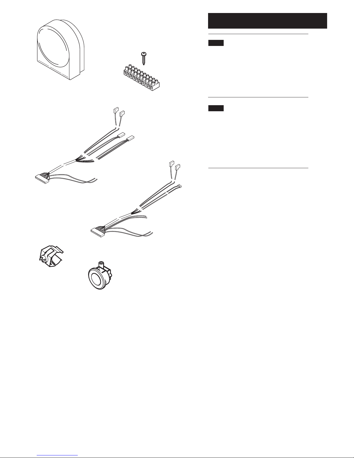
1.2 Contents of Kit
The kit contains:-
Outdoor Sensor Unit (i)
Terminal Strip & Screw (ii)
Replacement Harness (Combi) (iii)
Replacement Harness (System) (iv)
Return Pipe Sensor for System models (v)
Cable Grommet (vi)
1.0 Introduction
(i)
(ii)
(iii)
(iv)
(v)
(vi)
4© Baxi Heating UK Ltd 2010
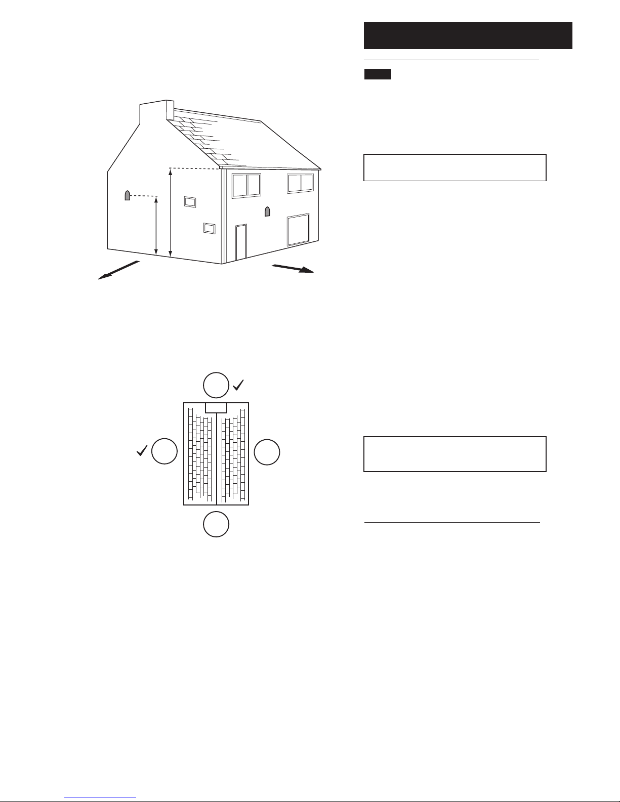
2.1 Location of the Sensor (Fig. 1)
1. The Sensor must be fixed to an external wall surface
of the property it is serving.
2. The Sensor should be positioned on a north to west
facing wall.
NOTE: DO NOT position it on a south facing wall in
direct sunlight !
3. The Sensor should be approximately half the height of
the living space of the property, and a minimum of 2.5m
above ground level.
4. It must be positioned away from any sources of heat
or cooling (e.g. flue terminal) to ensure accurate
operation. Siting the Sensor above doors and windows,
adjacent to vents and close to eaves should be avoided.
5. Once the position has been determined, prise the
cover off the sensor and mark through the sensor body
the two fixing holes and the larger hole for the wiring.
6. Drill & plug the two fixing holes (plugs and screws are
supplied with the Sensor). Also drill the hole for the
sensor wiring.
7. Insert the sensor wiring through the hole in the wall,
leaving sufficient length outside to allow connection. Seal
the hole. Note: 0.5mm 2 core cable is recommended
(the Sensor is a low voltage device).
NOTE: If it is not possible to pass the wiring through
the wall directly behind, remove the circular ‘knock-
out’ panel in the sensor base to allow connection.
8. Using the screws provided fit the body to the wall.
Insert the wires in the two-way terminal block and
secure them. Replace the Sensor cover.
2.0 Fitting the Outdoor Sensor
North West
1/2 H
2.5m Min
H
Fig. 1
N
S
WE
X
X

5
© Baxi Heating UK Ltd 2010
3.1 Connecting the Sensor
1. Ensure that the electrical supply to the boiler is isolated.
Undo the screws securing the facia and lift off the front panel.
Allow the facia to drop down (Fig. 2).
2. Undo the screws securing the cover and release the cover
retaining barbs from their slots. Disengage the rear of the
cover from the facia hinge pin and lift the cover away (Fig. 3).
3. Do not touch the PCB unnecessarily, and take care when
removing and fitting connectors. The use of an earthing
wristband is recommended.
4. Engage the 10 way terminal strip over the vertical flanges
and secure with the screw supplied (Fig. 4).
5. Disconnect the harness connector from position X400 on
the PCB (Fig. 5).
6. On Combi models disconnect from the Hall Effect Sensor,
DHW NTC and Water Pressure Switch (Figs. 6 & 7).
6. On System models disconnect from the Water Pressure
Switch and Heating Return Sensor (Figs. 8 & 9). Also remove
and discard the Heating Return Sensor.
3.0 Connection
Fig. 2
Fig. 3
Fig. 4
Fig. 5
X400
Fig. 6
Combi Hall Effect
Sensor Combi Water
Pressure Switch &
DHW NTC
System Water
Pressure Switch
Combi Models
System Models
System Heating
Return Sensor
Fig. 9
Fig. 8
Fig. 7

6© Baxi Heating UK Ltd 2010
3.1 Connecting the Sensor (continued)
7. Connect the appropriate new harness supplied to
position X400 on the PCB. On System models fit the new
Return Heating Sensor (Fig. 10).
8. Connect the harness terminals to the relevant boiler
components (see Figs. 6 to 9).
9. On Combi models connect the two brown wires on
the new harness to the terminal strip as shown (Fig. 11).
For System versions the white, blue and two brown wires
must be connected (Fig.12).
10. Route the wiring from the Outdoor Sensor to the
boiler, and using the cable grommet supplied (Fig. 13) pass
it through the hydraulic panel at the lower right.
11. Connect the Outdoor Sensor wiring to the the
terminals on the strip to which the brown wires are
connected (Combi Fig. 14, System Fig. 15)
12. Refit the cover, resecure the facia and door panel and
commission the boiler.
NOTE: This instruction booklet and all other boiler
literature must be left with the user for safe keeping.
3.0 Connection
br
br
br
brwb
Fig. 10
Fig. 11
Fig. 12
Fig. 13
Fig. 14
Fig. 15
New System Heating
Return Sensor
Combi
System
Combi
System
7
© Baxi Heating UK Ltd 2010
25
30
35
40
45
50
55
60
65
70
75
80
25
30
20
15
10
1015 5
20 -10-50
Outside Temp. (°C)
-15 -20
Boiler Flow Temp. (°C)
Curve 10
Curve 15
Curve 20
Curve 25
Curve 30
Curve 10
Curve 15
Curve 20
Curve 25
Curve 30
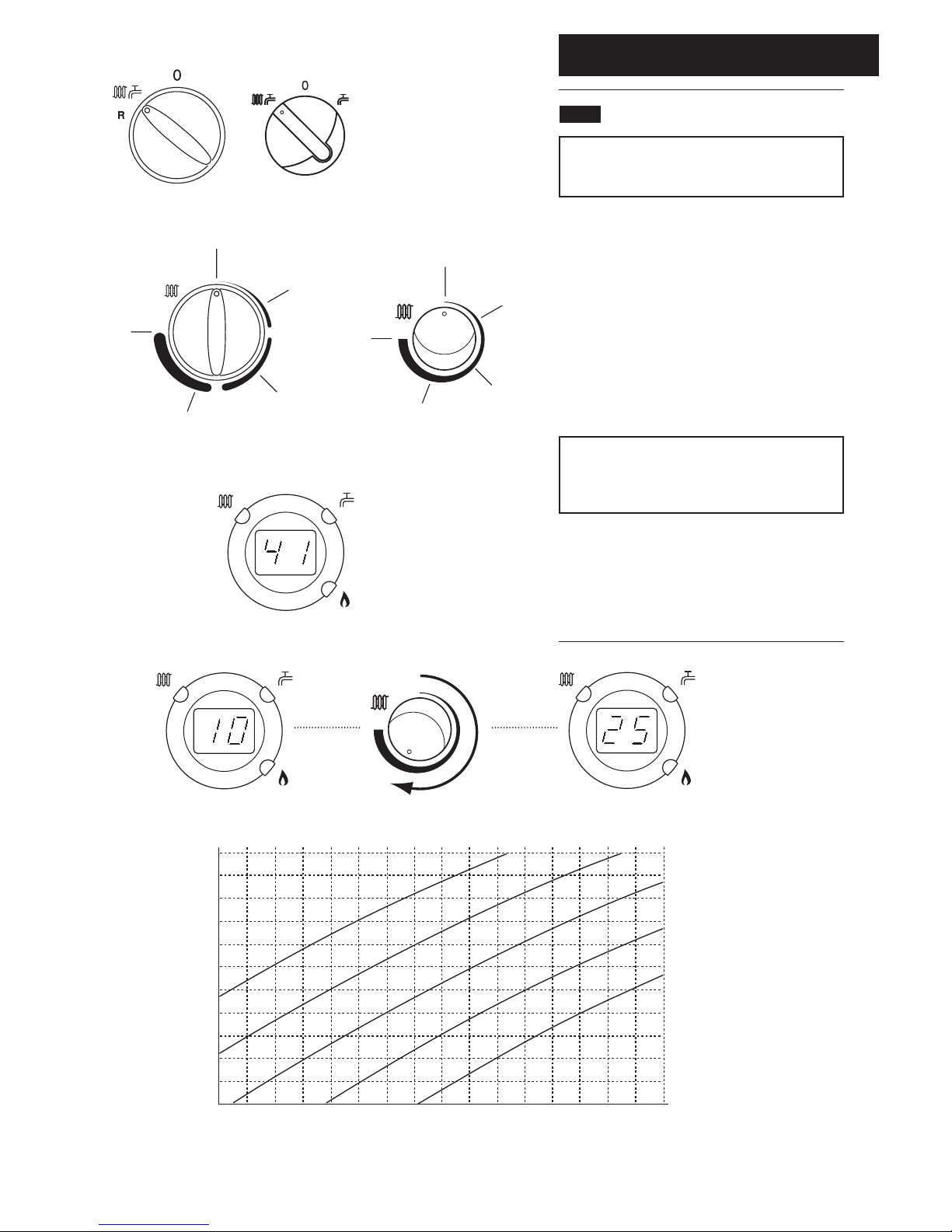
4.1 Setting the Sensor Curve
NOTE: Depending upon model of boiler either of two
types of Selector Switch and Central Heating Control
Knob will be fitted.
1. Ensure that there is power to the boiler (though it is
not necessary for there to be any heating demand). Turn
the selector switch to the boiler ON position (Fig. 16,
Combi versions illustrated).
2. The Central Heating Control Knob should be turned
clockwise to the position in Fig. 17 which corresponds
with the desired curve as shown on the graph below.
3. Normally the display will show the current temperature
of the water in the boiler (e.g. 41°C, Fig. 18). As the knob
is turned the display will show the selected curve (Fig. 19).
For example, if Curve 25 is selected, at an outside
temperature of 5°C the boiler flow temperature will
be 57°C. In the event of the outside temperature
falling to 0°C, the boiler flow will increase to 63°C.
3. Continue with the installation and commissioning of the
boiler as described in the Installation & Servicing
Instructions.
4. Explain to the user how to select a different
temperature curve
4.0 Setting
Fig. 16
Reset
Fig. 17
Fig. 18
Fig. 19

© Baxi Heating UK Ltd 2010 710356901 (04/10)
All descriptions and illustrations provided in this leaflet have been
carefully prepared but we reserve the right to make changes and
improvements in our products which may affect the accuracy of the
information contained in this leaflet. All goods are sold subject to our
standard Conditions of Sale which are available on request.
MULTIFIT
A Registered Trademark of Baxi Heating UK Ltd (3879156)
Brooks House, Coventry Road, Warwick. CV34 4LL
Technical Enquiries 0844 871 1555
Websites:- www.baxiheating.co.uk
e&oe
5.1 User Information
NOTE: The Central Heating Control Knob will NOT
operate in the same way as described in the User
Instructions supplied with the boiler !
1. Your installation has been fitted with an Outdoor
Sensor that acts as a Temperature Compensation Device.
2. The Outdoor Sensor enables the boiler to respond
effectively to changes in the ambient temperature outside
the dwelling.
3. As the outside temperature decreases, the boiler flow
temperature will increase, thus maintaining comfort levels
within the dwelling.
4. Your installer will have set the boiler according to the
anticipated outside temperature range.
5. If you require a different comfort level consult your
installer or follow the instructions in Section 4.0 of this
booklet.
5.0 User Information
This manual suits for next models
1
Table of contents
Other Baxi Accessories manuals

Baxi
Baxi Slinky User manual

Baxi
Baxi MULTIFIT Evacuated Tube Collector User manual

Baxi
Baxi VALOR FIRES 845 Instructions for use

Baxi
Baxi MULTIFIT SOL 200 L User manual

Baxi
Baxi MULTIFIT Evacuated Tube Collector Manual

Baxi
Baxi MULTIFIT Flue Systems Assembly instructions

Baxi
Baxi MULTIFIT Solar Collectors User manual

Baxi
Baxi 7703233 Guide

Baxi
Baxi EXTERNAL SENSOR KIT User manual


