manuals.online logo
Brands
  1. Home
  2. •
  3. Brands
  4. •
  5. BEA
  6. •
  7. Accessories
  8. •
  9. BEA 1SAFE User manual

BEA 1SAFE User manual

1/4
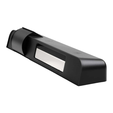
1SAFE
1/4
Do not cover the
sensor.
Avoid high intensity
lightning in the
detection field.
Avoid reflective
background or objects
in the detection field
of the sensor.
Do not touch the
optical parts.
FLICKERS
FLASHES
SLOWLY
ON OFF
RED LED is ON during detection
ORANGE LED flashes 1X after power on
Emitter Receiver
Cable
with
connector
Fixation
screw
Setup
adjustment screw
LED
DIP-switch
Push button
Front face
INSTALLATION TIPS
LED-SIGNAL
DESCRIPTION
USER’S GUIDE
ACTIVE INFRARED SAFETY SENSOR FOR AUTOMATIC DOORS
1
4
2
5
6
3
78
8
MOUNTING TEMPLATE
110
50
30
1
2
+4
0
-4
2/4
GREEN
OR
RED
Use the mounting template to cut
out the opening for the sensor.
Unclips the front face by inserting
a screwdriver as shown.
Push the push button shortly
to launch an automatic setup.
The LED will flash RED-GREEN.
When the LED turns OFF the
sensor is correctly installed.
Fasten the front face and test the
good functioning of the sensor.
If the LED continues flashing,
you have to adjust the sensor
further (see SETUP next page).
Connect the cable and insert
the sensor into the opening.
After inserting the sensor, fix
the 2 screws firmly.
The sensor can also be installed on the surface by using the surface
mount accessory (sold seperately).
Adapt the angle of the sensor.
INSTALLATION
OFF
RED-GREEN
NORMALLY OPEN
ACTIVE LOGIC
YELLOW-BLACK
NO POWER
NO DETECTION
DETECTION
NORMALLY CLOSED
PASSIVE LOGIC
YELLOW-WHITE
BROWN Power supply
12-24V AC/DC
COM
NC
NO
Monitoring
GREEN
YELLOW
WHITE
RED
BLACK
BLUE
ADDITIONAL ADJUSTMENTS
1
2
3
4
+
OK +
-
F1 F1
F2 F2
ON DIP
1
2 3 4
ON DIP
1
2 3 4
ON DIP
1
23 4
ON DIP
1
23 4
ON DIP
1
234
ON DIP
1
234
ON DIP
1
2 3 4
3/4
ON DIP
1
234
ON DIP
1
234
ON
SETUP
Frequency 2
Monitoring Active Low
UNCOVERED
ZONE
FREQUENCY
MONITORING
OFF
(Factory values)
ADDITIONAL ADJUSTMENTS
Automatic mode Manual mode
Frequency 1
Monitoring Active High
Do not touch the screw. It
should be positioned as
shown.
Push the push button
shortly to launch an
automatic setup.
LED flashes RED-GREEN.
Switch to manual mode
How?
Decrease (-) or increase (+) the uncovered
zone and check it by moving a white paper
up and down under the sensor.
When?
When 2 or more sensors are installed in
proximity to each other, it is recommended to
choose different frequencies to avoid crosstalk.
When?
When 2 or more sensors are installed in
proximity to each other, it is recommended to
choose different frequencies to avoid crosstalk.
When?
When the monitoring input mode is active high
or
when no monitoring is required.
When?
When the monitoring input mode is active low.
Big (40cm at 2.2m)
When?
When increased immunity to disturbances
is required.
Relaunch a setup after changing dip switch 2
Small (25cm at 2.2m)
When?
When increased door safety is required.
Relaunch a setup after changing dip switch 2
When?
- low reflectivity of background
- no background or > 3mmounting height
- mounting height < 1.6m
- uncovered zone > 40cm
GREEN
RED
4x ORANGE
RED-GREEN
OFF
When the application requires specific adjustments, you can
adapt the sensor by using the dip switches.
Do not move the white
paper horizontally!
BEA SA - LIEGE Science Park - Allée des Noisetiers 5 - B-4031 Angleur - T +32 4 3616565 - F +32 4 3612858 - [email protected] - www.bea.be
4/4
active infrared
presence detection by distance measurement
35mm x 70mm (at 2.2m mounting height)
64ms
0.6m - 3m
12V - 24V AC/DC -5% / + 10%
50 - 60 Hz
120mA @ 24V AC / 80mA @ 24V DC
relay (free of potential contact)
42V AC/DC
1A (resistive)
30W (DC) / 60VA (AC)
0.5s
min. 10% at IR-wavelength of 850nm
-25°C - +55°C; 0-95% rel. humidity, non condensing
IP53
Electromagnetic compatibility (EMC) according to
144mm (L) x 40mm (H) x 50mm (D)
ABS (black)
2.5m
2004/108/EC
Technology:
Detection mode:
Detection field:
Response time:
Mounting height:
Supply voltage:
Mains frequency:
Max. current consumption:
Standard output:
Max. contact voltage:
Max. contact current:
Max. switching power:
Hold time:
Reflectivity:
Temperature range:
Degree of protection:
Norm conformity:
Dimensions:
Housing material:
Length of main cable:
Specifications are subject to changes without prior notice
42.0608 - V3 / 01.13
TROUBLESHOOTING
RED
OFF
RED
RED
4x ORANGE
Launch setup and check adjustment.
Bad adjustment of the uncovered zone.
The monitoring mode is wrong.
Launch a manual setup.
Change the position of DIP 4.
Check wiring: connect RED and
BLUE to monitoring output.
If the door control has no monitoring:
do not connect RED and BLUE wires.
Launch a manual setup.
Launch a new setup.
The signal received from background
is too weak.
The distance to the floor has changed
due to external factors.
The sensors interfere with each other
due to overlapping detection zones.
You are standing inside the detection field. Step outside the detection field.
Check if the sensor is installed
correctly.
Range is too short.
The signal received from background is
too weak.
Increase the distance between the
sensors or select a different
frequency on each sensor.
Check if proximate modules have
different frequencies.
Increase the uncovered zone.
The sensor detects
eratically.
The red LED is
permanently ON.
The LED is OFF,
but the relay “clicks”.
The red LED
flickers.
The orange LED
flashes 4x
during setup.
The red LED
flashes
during setup.
SYMPTOM POSSIBLE CAUSES CORRECTIVE ACTION
TECHNICAL SPECIFICATIONS
The wiring is not correct.
1 optocoupler (free of potential contact)
30V
High state: >10V
Low state: <1V
Monitoring input:
Max. contact voltage:
Voltage threshold:
The colour version of this user's guide and other technical documentation are available on our website
(www.bea.be) or can be requested by phone (+32 4 361 65 65) or mail ([email protected]).
Other BEA Accessories manuals

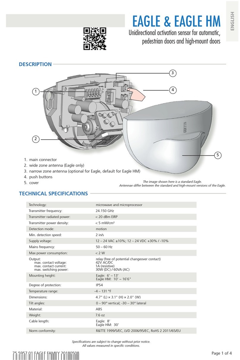
BEA Eagle HM User manual

BEA

BEA Eagle HM User manual

BEA IS40P User manual

BEA

BEA IS40P User manual

BEA WIZARD-C User manual

BEA

BEA WIZARD-C User manual

BEA Falcon User manual

BEA

BEA Falcon User manual

BEA LZR-WIDESCAN User manual

BEA

BEA LZR-WIDESCAN User manual

BEA WIZARD PLUS User manual

BEA

BEA WIZARD PLUS User manual

BEA IXIO-DT3 User manual

BEA

BEA IXIO-DT3 User manual

BEA CGS-KF112 User manual

BEA

BEA CGS-KF112 User manual

BEA MAGIC SWITCH CHROMA 86 User manual

BEA

BEA MAGIC SWITCH CHROMA 86 User manual

BEA CGS-MF User manual

BEA

BEA CGS-MF User manual

BEA IS40 User manual

BEA

BEA IS40 User manual

BEA SUPERSCAN-T User manual

BEA

BEA SUPERSCAN-T User manual

BEA MAGIC SWITCH MS09 User manual

BEA

BEA MAGIC SWITCH MS09 User manual

BEA IS40 User manual

BEA

BEA IS40 User manual

BEA Eagle Operator's manual

BEA

BEA Eagle Operator's manual

BEA Eagle One HM User manual

BEA

BEA Eagle One HM User manual

BEA IXIO-DP1 User manual

BEA

BEA IXIO-DP1 User manual

BEA IS40 User manual

BEA

BEA IS40 User manual

BEA BODYGUARD III GT 300 User manual

BEA

BEA BODYGUARD III GT 300 User manual

BEA Halma PBS45 Series User manual

BEA

BEA Halma PBS45 Series User manual

BEA LZR-MICROSCAN1UT User manual

BEA

BEA LZR-MICROSCAN1UT User manual

BEA FALCON DR User manual

BEA

BEA FALCON DR User manual

BEA SEAGLE ONE User manual

BEA

BEA SEAGLE ONE User manual

BEA BEAMBOX User manual

BEA

BEA BEAMBOX User manual

Popular Accessories manuals by other brands

M Climate MC-LW-CO2-01 user manual

M Climate

M Climate MC-LW-CO2-01 user manual

Silvercrest SSA01A Operation and safety notes

Silvercrest

Silvercrest SSA01A Operation and safety notes

HAMPTON BAY HB-7738-03 Use and care guide

HAMPTON BAY

HAMPTON BAY HB-7738-03 Use and care guide

I-View S200 manual

I-View

I-View S200 manual

Silvercrest SSSE 300 A1 operating instructions

Silvercrest

Silvercrest SSSE 300 A1 operating instructions

Silvercrest TPB 10000 A1 Operation and safety notes

Silvercrest

Silvercrest TPB 10000 A1 Operation and safety notes

USR IOT USR-WP1 user manual

USR IOT

USR IOT USR-WP1 user manual

Glastender LP60 Operation manual

Glastender

Glastender LP60 Operation manual

ledscom LC-SS-9128 Assembly instructions

ledscom

ledscom LC-SS-9128 Assembly instructions

Silvercrest 354079 2010 operating instructions

Silvercrest

Silvercrest 354079 2010 operating instructions

V-tech ErisTerminal VDP800 quick start guide

V-tech

V-tech ErisTerminal VDP800 quick start guide

Mark U12-4440 Installation and operation manual

Mark

Mark U12-4440 Installation and operation manual

MaxiCosi TS377 instructions

MaxiCosi

MaxiCosi TS377 instructions

REV FUNKGONG VIVO operating instructions

REV

REV FUNKGONG VIVO operating instructions

Glowworm 20040796 Installation and instructions for use

Glowworm

Glowworm 20040796 Installation and instructions for use

Profi Care PC-WZD 3061 instruction manual

Profi Care

Profi Care PC-WZD 3061 instruction manual

I.SOUND DGIPAD-4519 datasheet

I.SOUND

I.SOUND DGIPAD-4519 datasheet

Sferalabs ESRB10X quick reference

Sferalabs

Sferalabs ESRB10X quick reference

manuals.online logo
manuals.online logoBrands
  • About & Mission
  • Contact us
  • Privacy Policy
  • Terms and Conditions

Copyright 2025 Manuals.Online. All Rights Reserved.