75.5351.02 EN 20080317 (75.5350) Page 7 of 7
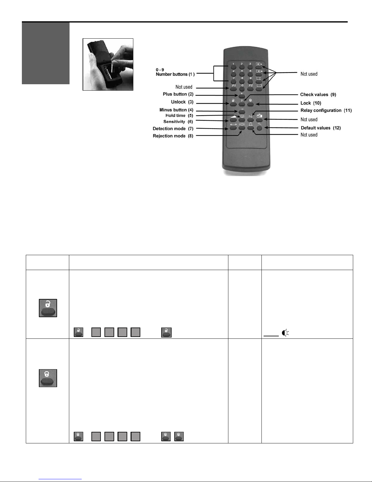
During the manual adjustment session:
•Each press on the right button increases the number of the displayed parameter by one unit;
•Each press on the left button increases the value of the displayed parameter by one unit.
NOTE: When the maximum value or the highest number of the parameter is reached, this will return
to their minimum values.
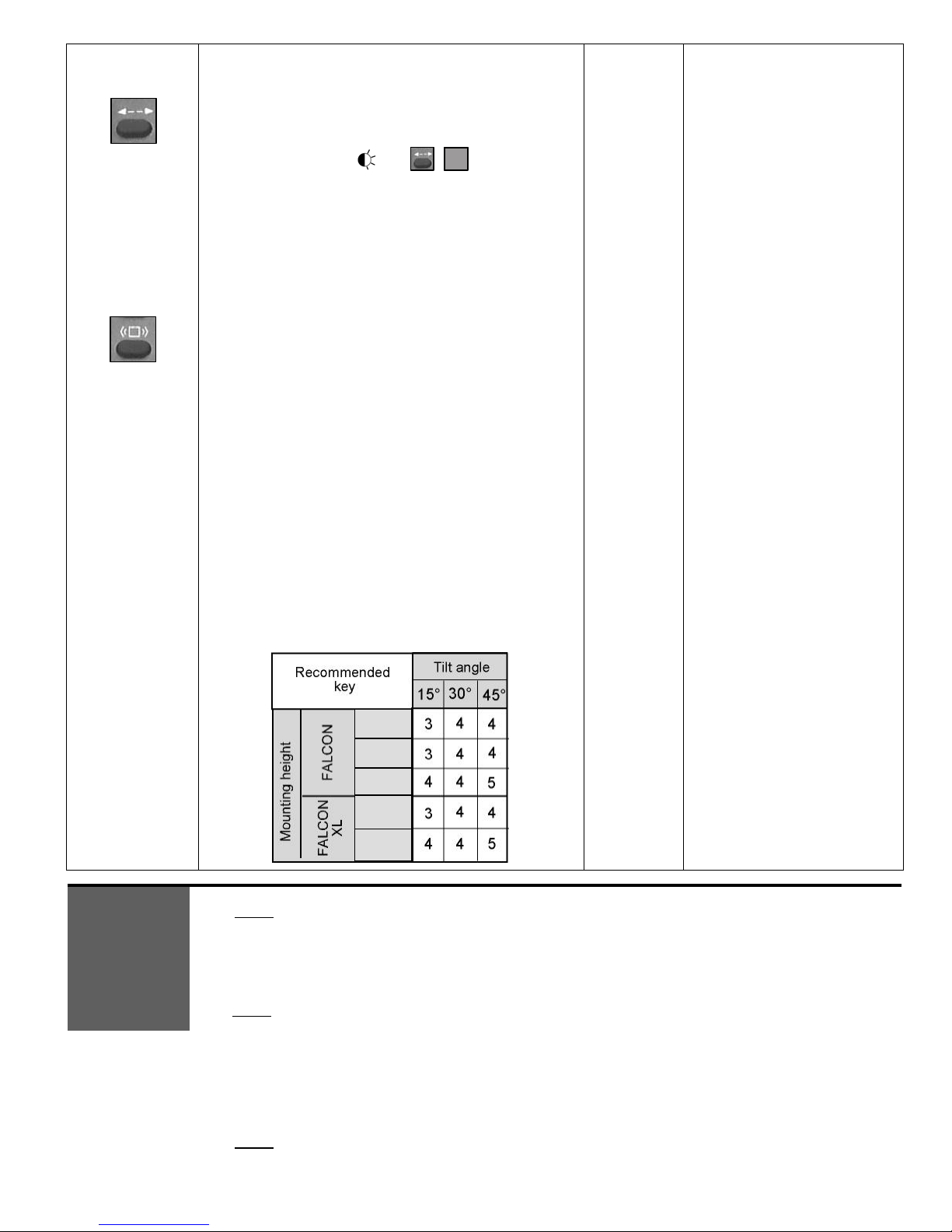
Parameter
Number Parameter Values Factory setting
1 Sensitivity 0 - 9 7
2 Hold time 0 - 9 0
3 Relay configuration 1 - 4 1
4 Detection mode 1 - 3 2
5 Pedestrian
rejection mode 1 - 5 1
For example, to change the sensitivity from 7 to 9 and the rejection mode from ‘detection of all kind of
targets in motion’ to High ‘Pedestrian/parallel traffic’ rejection.
•Press any button for 2 seconds to enter the adjustment session and then release it.
•The red LED flashes once (parameter 1 = sensitivity) and the green LED flashes 7 times (sensitivity=7).
•Press the left button twice to increase the sensitivity from 7 to 9.
• The red LED still flashes once (parameter 1 = sensitivity) but the green LED flashes 9 times now
(sensitivity=9).
•Now press the right button 4 times to move to function 5 (rejection mode) ;
•The red LED flashes 5 times (parameter 5 = rejection mode) and the green LED flashes once
(‘detection of all kind of targets in motion’) ;
•Press the left button 4 times to set the parameter to High ‘Pedestrian/parallel traffic’ rejection.
•The red LED still flashes 5 times (parameter 5 = rejection mode) but the green LED flashes 5 times now
(High ’Pedestrian/parallel traffic’ rejection).
•Press any button during 2 seconds to end the adjustment session and then release it.
SYMPTOM PROBABLE CAUSE CORRECTIVE ACTION
The door will not open and the red
LED does not light up. The sensor power is off. Check power supply.
Check the supply voltage.
The sensor ‘sees’ the door
moving. Increase the tilt angle and/or reduce
the sensitivity.
The door opens and closes
constantly. When closing the door creates
vibrations picked up by the
sensor.
Ensure that the sensor is correctly
fixed.
If the rejection mode is set at level 1,
set this parameter to level 2.
Reduce the sensitivity.
Switch to unidirectional mode.
The door opens and closes after a
given time for no apparent reason. The sensor is picking up
unintended traffic motion. Reduce the sensitivity.
Reduce the tilt angle.
The sensor is not capable of
activation near the door. The tilt angle is too large. Reduce the tilt angle.
The batteries are weak.
Check the batteries insertion.
Change the batteries.
The sensor does not respond to the
remote control. The access code has been
changed. •Press both push buttons
simultaneously to reset all the
parameters to the factory values.
•Or switch off the power supply.
Within the first minute after the
power on, change the access code.
TROUBLE-
SHOOTING
TROUBLE-
SHOOTING
Do not leave problems unresolved. If a satisfactory solution cannot be achieved after troubleshooting a problem,
please call BEA, Inc. If you must wait for the following workday to call BEA, leave the door inoperable until
satisfactory repairs can be made. Never sacrifice the safe operation of the automatic door or gate for an
incomplete solution.
The following numbers can be called 24 hours a day, 7 days a week. For more information, visit www.beasensors.com.
US & Canada: 1-866-249-7937 Midwest: 1-888-308-8843
Northeast: 1-866-836-1863 West: 1-888-419-2564
Southeast: 1-800-407-4545 Canada: 1-866-836-1863