12
XXS XS S > >> > LXL XXL
1 s 2 s
.5 s 4 s 5 s3 s 6 s 8 s7 s 9 s
See FUNCTION
DESCRIPTIONS below
3 4 5 6
12
REJECTION MODE
DOOR EXAMPLE
REMOTE CONTROL PARAMETERS
Motion Detection Settings
Page 6 of 9 75.5695.01 EN 20120113
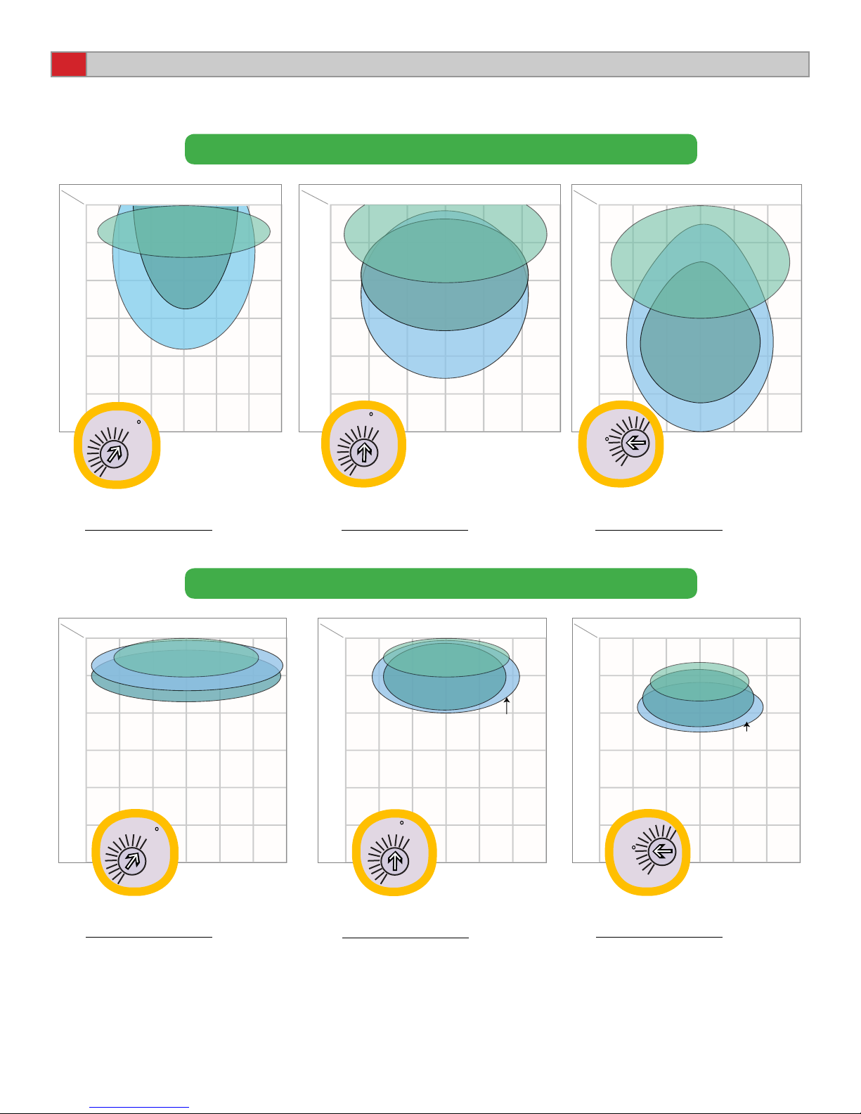
bi uni
SENSITIVITY
DETECTION
MODE
uni
depart
bi = two-way detection
uni = one-way detection towards sensor
uni depart = one-way detection away from sensor
Green
Red
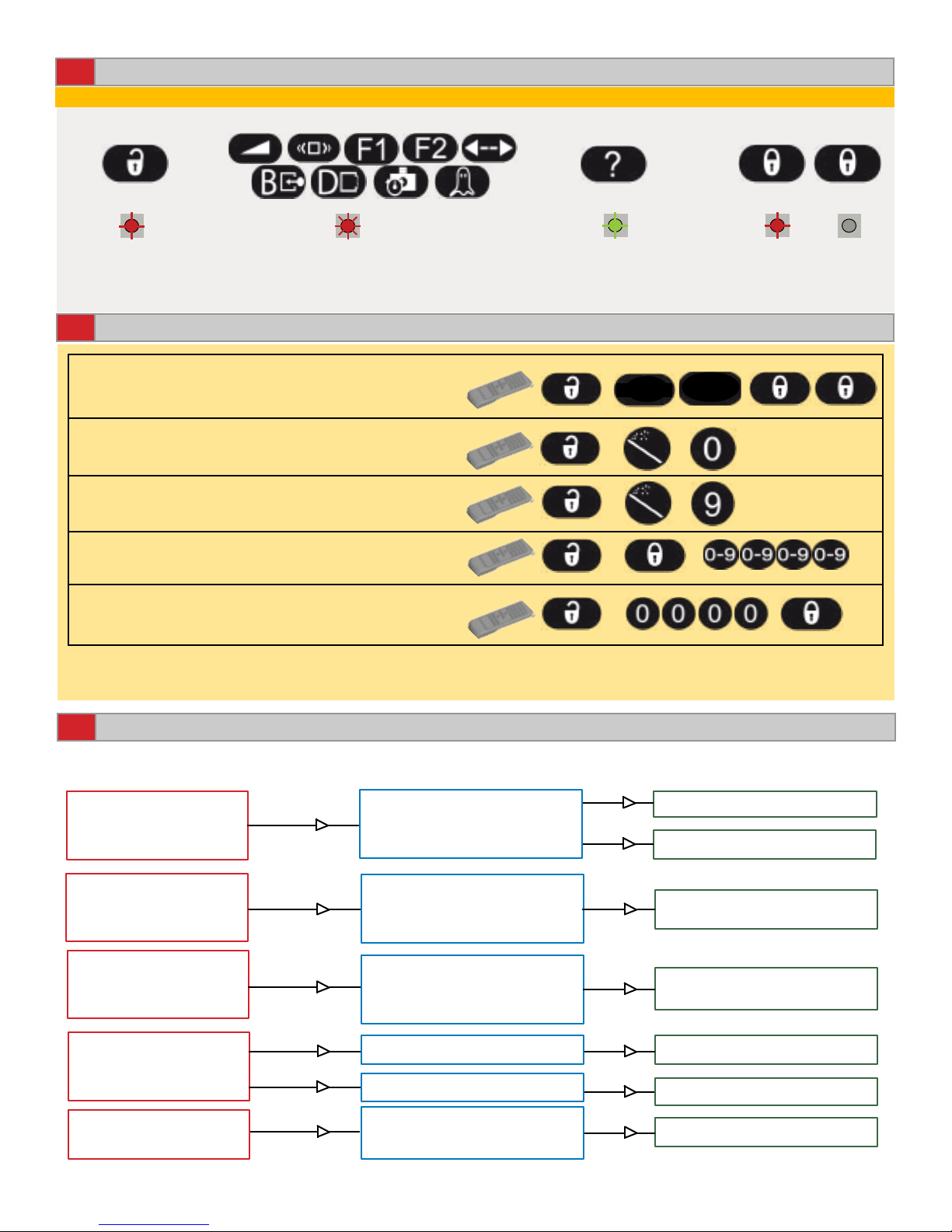
OUTPUT CONFIGURATION
OUTPUT
CONFIGURATION
PRESENCE RELAY IS40 / IS40XL LED
0 - 6: ALL MODES Activates when object is in presence zone.
ACTIVATION RELAY IS40 / IS40XL LED
0: STANDARD MODE Activates when motion detected.
1: PULSE ON ENTRY Activates if object motion is detected and then object
enters presence zone.
2: PULSE ON EXIT Activates if object motion is detected and then object
exits presence zone.
3: PULSE ON ENTRY FIRST / LAST LINE
(See Example to the Left)
Activates if object motion is detected and then object
enters presence zone (rst or last line).
4: PULSE ON EXIT FIRST / LAST LINE
(See Example to the Left)
Activates if object motion is detected and then object
exits presence zone (rst or last line).
5: REMAINS ACTIVE UNTIL PRESENCE
ZON E IS CLEARED (Regardless of Motion)
Activates when motion is detected and remains active
until the presence zone is cleared.
6: REMAINS ACTIVE UNTIL PRESENCE
ZONE IS CLEARED (Regardless of Motion)
Activates when motion is detected and IR is detected
and remains active until the presence zone is cleared.
FIRST LINE
LAST LINE
FREQUENCY
AUTOMATIC
LEARN TIME
IR IMMUNITY low medium high
1 min 2 min30 s 10 min 20 min5 min 1 h 2 h1.5 h
IR / Presence Settings
low high
∞
FACTORY
VALUES
=
ACTIVATION RELAY
HOLD TIME
Note:The automatic learn time is the amount of time a static
object needs to be in the IR eld before the sensor will learn it
FUNCTION DESCRIPTION
1: Detection of all kind of Targets
in Motion
2: Detection of all kind of Targets in Motion
+ Interference Immunity
3: Low ‘Pedestrian/Parallel trafc’ Rejection
+ Interference Immunity
4: Medium ‘Pedestrian/Parallel trafc’
Rejection + Interference Immunity
5: High ‘Pedestrian/Parallel trafc’ Rejection
+ Interference Immunity
6: Extra High ‘Pedestrian/Parallel trafc’ Rejection
+ Interference Immunity
REJECTION MODE