BEA
SA
|
LIEGE
Science
Park
|
ALLÉE
DES
NOISETIERS
5
-
4031
ANGLEUR
[BELGIUM]
|
T
+32
4
361
65
65
|
F
+32
4
361
28
58
|
[email protected] |
WWW
.BEA.BE
2
1
4
5
1
2
1
1
2
1
2
1
2
1
2
1
2
1
1
1
1
1
2
1
1
2
3
1
2
6
7
1
1
1
BEA
ri
ina
instructions
.71
V
11.1
BEA hereby declares that the ACTIV8 THREE PULSE is in conformity with the basic requirements and the
other relevant provisions of the directives 1999/5/EC, 2004/108/EC and 2006/42/EC.
Notified Body for EC inspection: 0044 - TÜV NORD CERT GmbH, Langemarckstr. 20, D-45141 Essen
Angleur, November 2010 Jean-Pierre Valkenberg, Authorized representative
The complete declaration of conformity is available on our website: www.bea.be
LED-SIGNALS
The ORANGE LED
flashes 1 x.
The ORANGE LED
flashes 2 x.
The ORANGE LED
flashes 4 x.
The ORANGE LED
flashes 5 x.
The ORANGE LED
flashes every second.
The ORANGE LED
is on.
The RED LED flashes
quickly after an
assisted setup.
The RED LED
lights up
sporadically.
The GREEN LED
lights up
sporadically.
The sensor goes into
security mode.
The sensor signals
an internal fault.
Irregularities in the
power supply
The sensor receives
not enough IR-energy.
The sensor receives
too much IR-energy.
The sensor encounters
a memory problem.
The sensor vibrates.
The sensor sees the door
during the assisted setup.
The sensor sees the door.
The sensor is disturbed by
lamps or another sensor.
The sensor is disturbed
by the rain.
The sensor is disturbed by
rain and/or leaves.
The sensor vibrates.
Ghosting
The sensor sees the door
or other moving objects.
Check power supply.
Check wiring.
Use the 1 m prism if possible.
Check the angle of the IR-curtains.
Cut and restore power supply.
Cut and restore power supply.
If orange LED lights up again, replace sensor.
Check the angle of the IR-curtains.
Launch a new assisted setup.
Attention: Do not stand in the detection field!
Use a low energy prism if possible.
Check the angle of the IR-curtains.
Check if the sensor is fastened firmly.
Check position of prism and cover.
Choose a different frequency by remote control.
Increase the IR-immunity filter to value 2 or 3.
Increase radar-immunity filter by remote control.
Change radar antenna angle.
Check if the sensor is fastened firmly.
Check position of cable and cover.
Change radar antenna.
Change radar field size (sensitivity).
Remove the objects if possible.
Launch an assisted setup and adjust the IR angle.
Cut and restore power supply.
If orange LED flashes again, replace sensor.
Only for EC countries: According to the European Guideline 2002/96/EC for Waste Electrical and Electronic Equipment (WEEE)
The ORANGE LED
flashes 6 x.
The ORANGE LED
flashes 7 x.
The radar sensor output is
faulty.
The radar sensor encounters
a hardware problem.
Replace sensor.
The sensor is disturbed.
Replace sensor.
Change radar antenna angle.
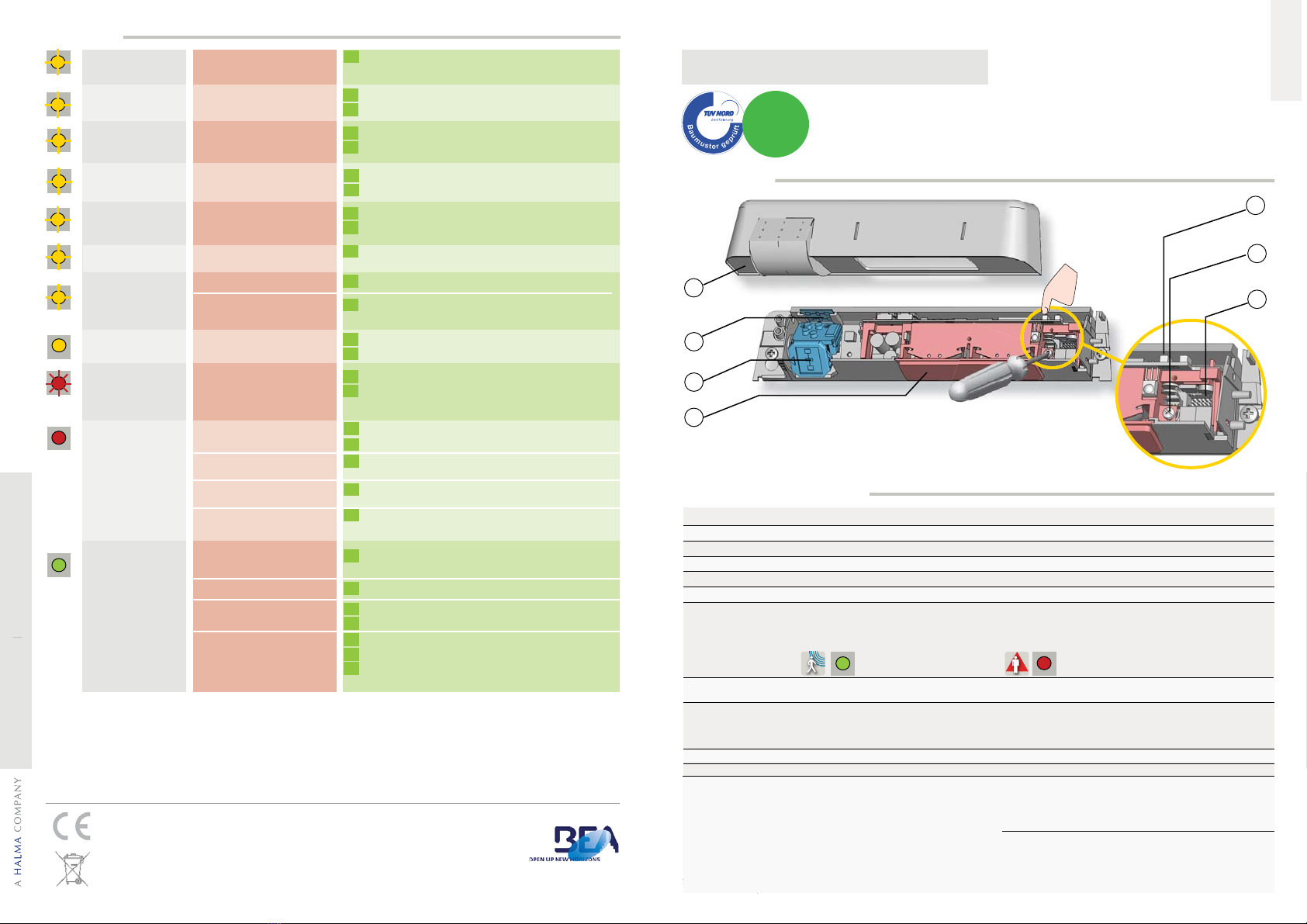
ACTIV8 THREE PULSE
3
2
4
1
5
6
7
E
R
L
A
U
B
T
Z
E
R
T
I
F
I
Z
I
E
R
U
N
G
N
A
C
H
DIN 18650
E
N
A
B
L
E
S
A
C
C
O
R
D
A
N
C
E
W
I
T
H
TECHNICAL SPECIFICATIONS
1. IR-prism (2 m)
2. radar antenna (wide field)
3. radar antenna (narrow field)
4. cover
DESCRIPTION
Presence
Typical response time: <128 ms (max. 500 ms)
Active infrared with background analysis
Spot diameter: 0.1 m (typ)
Number of spots: 24 or 12 by curtain
Number of curtains: 2
From -4 ° to +4 ° (adjustable)
0.3 s to 1 s (not adjustable)
Transistor (NPN open collector) requiring ext. pull-up resistor
Max. output current: 25 mA
Max. switching power: 40 V DC
Max. pulse amplitude (detection state or fail state): 0,8 V
Input Impedance: 100 kΩ
Max. input voltage: 30 V DC
External pull-up resistor: < 470 Ω (check compatibility)
Min. Pulse amplitude (Vpp): > 50% of sensor supply voltage
Max. Pulse duration: 100 μs @ 25 mA output current
Min. time interval between pulses: > pulse duration
ENGLISH
Opening & safety sensor
for automatic sliding doors in escape routes
5. push buttons
6. IR-curtain ajustment screw
7. main connector
12 V - 24 V AC +/-10% ; 12 V - 30 V DC -5%/+10% (to be operated from SELV compatible power supplies only)
< 3 W
1.8 m to 4 m (< 3 m to enable DIN 18650-conformity)
-25 °C to +55 °C
IP54
5 years
R&TTE 1999/5/EC; EMC 2004/108/EC; MD 2006/42/EC; EN 12978
EN ISO 13849-1:2008 Performance Level «d» CAT. 2
(under the condition that the door control system monitors the sensor at least once per door cycle)
Supply voltage:
Power consumption:
Mounting height:
Temperature range:
Degree of protection:
Expected lifetime:
Norm conformity:
Motion
Min. detection speed: 5 cm/s
Microwave doppler radar
Transmitter frequency: 24.150 GHz
Transmitter radiated power: < 20 dBm EIRP
Transmitter power density: < 5 mW/cm2
From 15 ° to 50 ° vertical (adjustable)
0.5 s to 9 s (adjustable)
Potential linked current source
No detection: current source ON
Max. open circuit voltage: 6.5 V
Output voltage available at 10 mA: 3 V min.
Typical load: up to 3 optocouplers in series
Detection: current source OFF
Leakage current: < 100 μA
Open-circuit remained voltage: < 500 mV
Detection mode:
Technology:
Angle:
Hold time output signal:
Output/Input:
GREEN
LED
RED
LED
peci
cations are subject to changes without prior notice
All values measured in optimal conditions.
ll values measured in o
timal conditions
Other use of the device is outside the
permitted purpose and can not be
guaranteed by the manufacturer.
The manufacturer cannot be held
responsible for incorrect installations or
inappropriate adjustments of the sensor.
Please keep for further use
Designed for colour printing
For product version 0600 and more


