x
Page 8 of 20 75.0034.03 ULTIMO 20220120
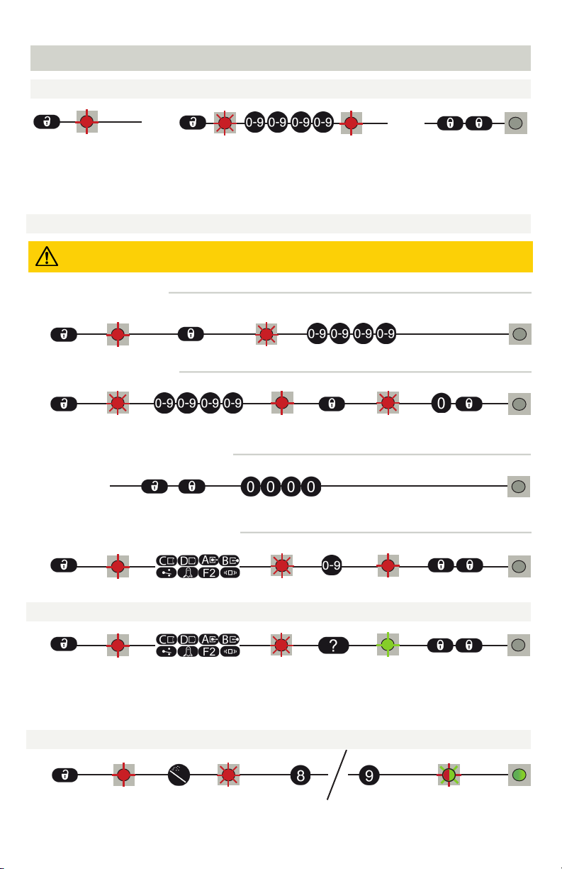
HOW TO USE THE REMOTE CONTROL
UNDERSTANDING LED ACTIVITY
ACCESS CODES
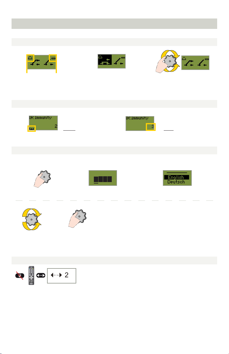
CHECKING A VALUE
RESTORING TO FACTORY VALUES
The access code is recommended for sensors installed close to each other.
After unlocking, the red LED
flashes and the sensor can be
adjusted by remote control.
If the red LED flashes quickly after unlocking, you need
to enter an access code from 1 to 4 digits.
If you do not know the access code, cycle the power.
During 1 minute, you can access the sensor without
introducing any access code.
To end an adjustment
session, always lock the
sensor.
Enter the existing code
x= number of flashes = corresponds to the remote control button
assignment for the current setting (see page 16 for parameter assignments)
Example: For a sensor still programmed to factory default, the value check
for AIR Presence Time will result in 2 green LED blinks.
full reset partial reset
It is recommended to use a different access code for each sensor in order to avoid changing settings on
both sensors at the same time.
SAVING AN ACCESS CODE
DELETING AN ACCESS CODE
ADJUSTING ONE OR MORE PARAMETERS
READ BEFORE BEGINNING PROGRAMMING/SETUP
full reset = restores to factory defaults
partial reset = restores all settings except monitoring and outputs
CYCLE
POWER
DELETING AN UNKNOWN ACCESS CODE