BEA LZR SIGMA User manual

©BEA | Original Instructions
75.5929.01 LZR-SIGMA 20210630 Page 1 of 17
People-counting solution
PRODUCT INFORMATION 2
What's in the box 2
Labels 2
LED indications 3
Technical specications 3
HOW IT WORKS 4
How to connect - power 4
How to connect - network 4
INSTALLATION 5
Installation preparation 5
Installation location tips 7
Mounting options 9
Before you begin 9
Mounting 10
SETUP 11
ADDITIONAL FEATURES 14
INSTALLATION VERIFICATION 15
TROUBLESHOOTING 16
APPENDIX: SENSOR LOG 17
CONTENTS

©BEA | Original Instructions
75.5929.01 LZR-SIGMA 20210630 Page 2 of 17
Scan
me to
start
X0006F
FRONT FACE
PRODUCT
LABEL
COUNTING HEAD
QR CODE
SURFACE
MOUNTING BASE
SCREWS
SENSOR QR CODE
STICKER
PRODUCT INFORMATION
WHAT’S IN THE BOX
WHAT YOU'LL NEED
LABELS
MAC
ADDRESS
SENSOR
QR CODE
side of box
When installing multiple sensors at one site, It is considered best practice to log each sensor and its location.
Please use the log chart (Appendix) by adhering the extra sticker (loose in box) in the appropriate space and
log the site location.
• drill
• screwdriver, Phillips head
• wire cutters (optional)
• LZR-SIGMA app
• power (see page 4 for power options)
InformationColor
LZR®-SIGMA
IP : 192.169.1.2
user: H12345
password: password
MAC: 04:71:4B:51:23:45 SCAN ME TO START
H12345
TILT SCREW

©BEA | Original Instructions
75.5929.01 LZR-SIGMA 20210630 Page 3 of 17
= solid LED
= ashing LED
LED SIGNAL CAUSE ACTION
No internet connection
The ethernet conguration is wrong or no cellular network is available
Check the network connection
Check if port 8883 is opened
Device is not powered
Note that the LED can also be o when the
device is in normal operation
Check power supply
Communicating with the app or with
Sensorio.
Connected to the network
The device is communicating
Searching for network The device is connecting to the network
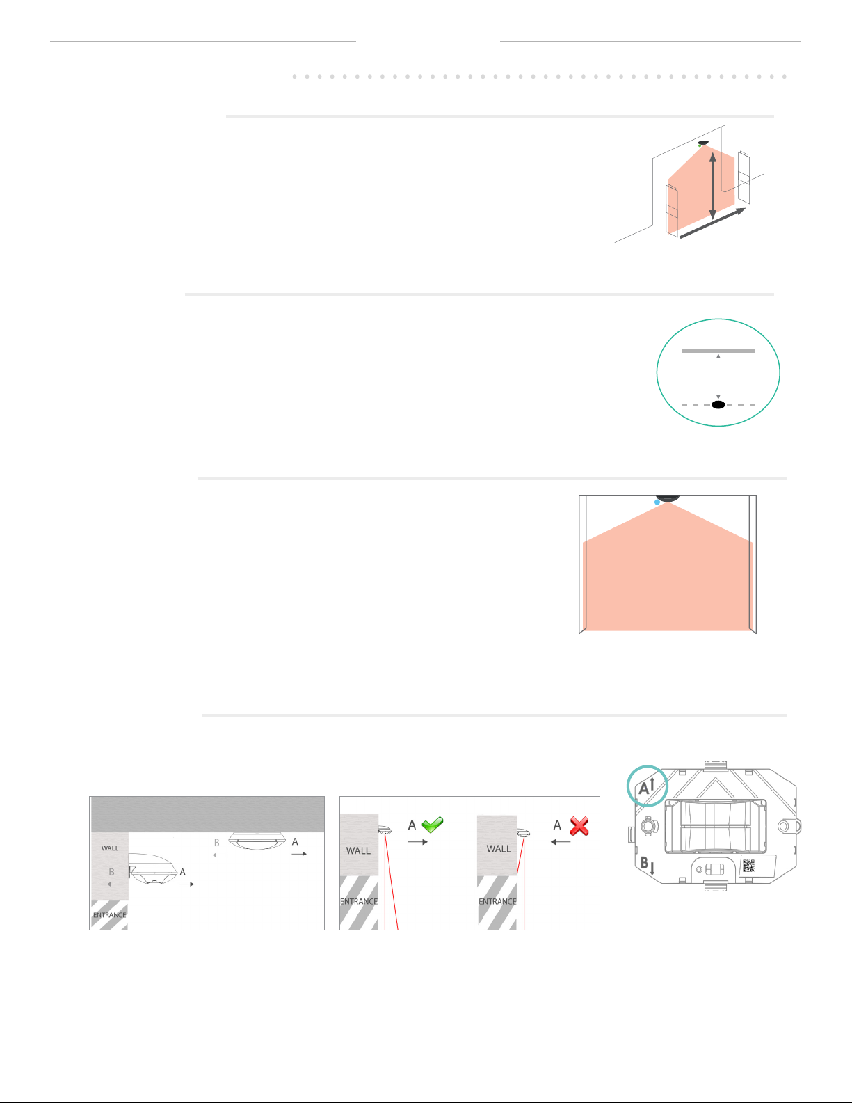
Learning Dene the max. limit on your right or left
Error If this occurs, please contact BEA.
Updating Connection to the device is impossible
Wait for update completion
At least one of the following port is not opened:
123 (UDP) / 22 (TCP) / 443 (TCP) / 8883 (MQTTS)
Check network settings with your IT support
See page 4 for more information on connecting.
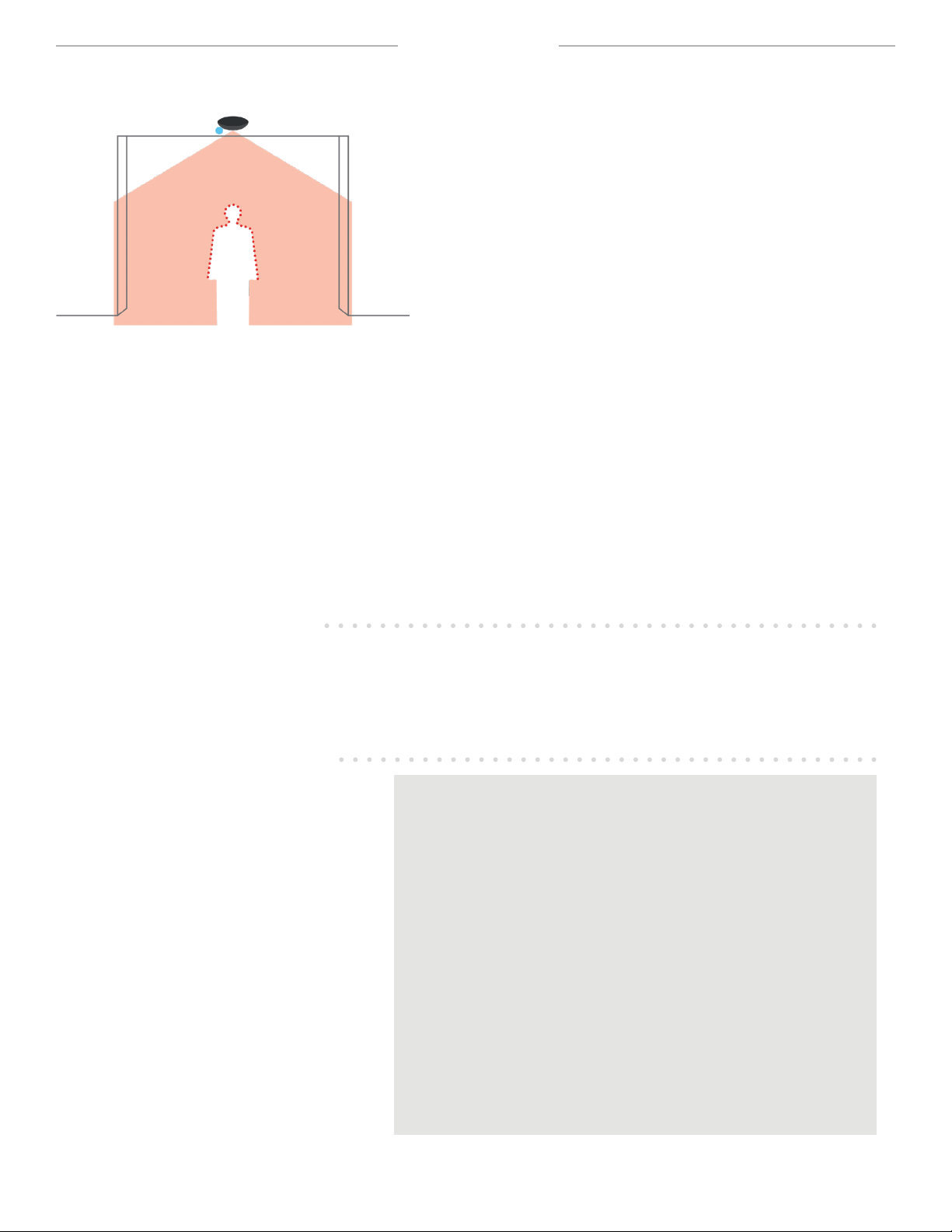
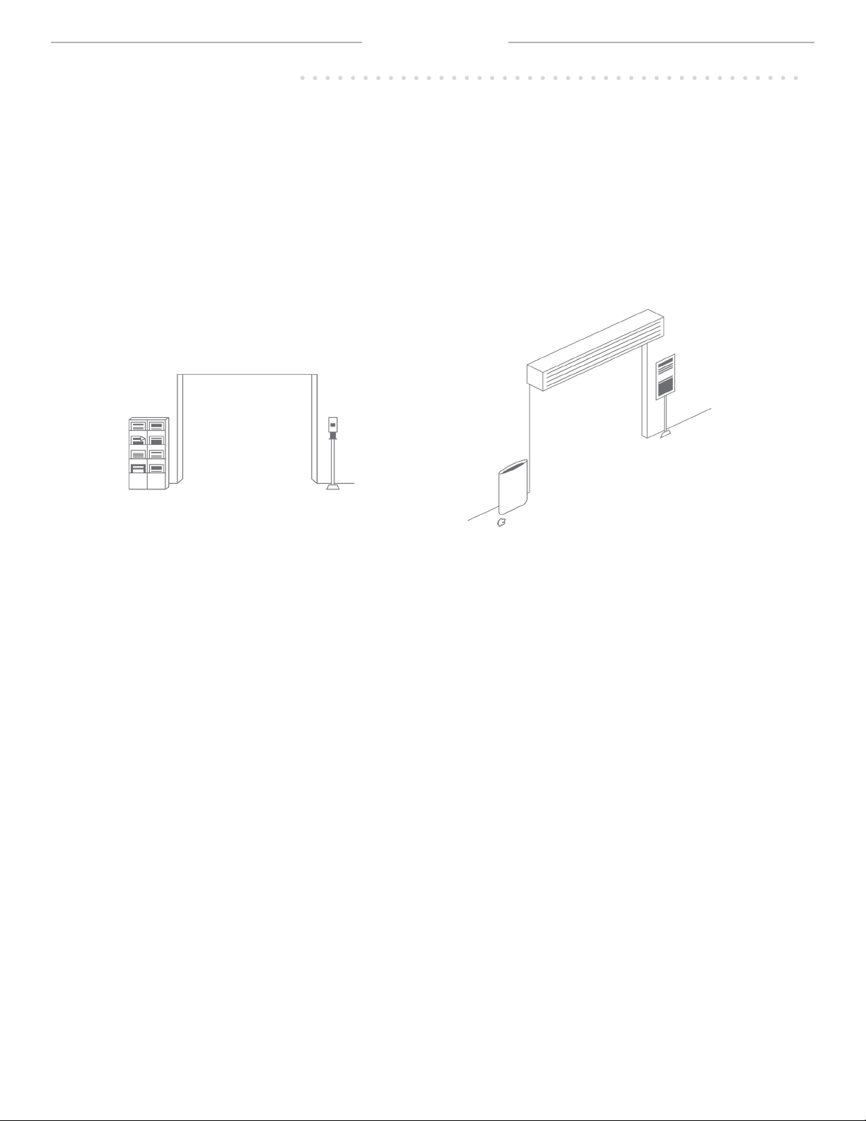
PRODUCT INFORMATION
Technology LASER scanner, time-of-ight measurement
Emission characteristics - IR LASER Wavelength 905 nm ; average output power 0.05 mW; Class 1 (EN 60825)
Device dimensions 7.87 in [L] x 5.59 in [W] x 2.40 in [H] (elliptical)
(if mounted with recessed accessory : visible height 37 mm, invisible height 65 mm)
Temperature range -13 –131 °F if powered (storage temperature -31 –158 °F)
Humidity 0 - 95% non-condensing
Power 24 VDC ± 10% External DC power or PoE (IEEE802.3af)
Power consumption Max. 12 W/Peak - Average 6 W
Data transfer 3G/2G cellular, Ethernet (cable cat. 5/6)
Supported frequencies / Power GSM 850 - 824 to 849 MHz (Tx) - 869 to 894 MHz (Rx) - 2 W (Max. Power)
E-GSM 900 - 880 to 915 MHz (Tx) - 925 to 960 MHz (Rx) - 2 W (Max. Power)
DCS 1800 - 1710 to 1785 MHz (Tx) - 1805 to 1880 MHz (Rx) - 1 W (Max. Power)
PCS 1900 - 1850 to 1910 MHz (Tx) - 1930 to 1990 MHz (Rx) - 1 W (Max. Power)
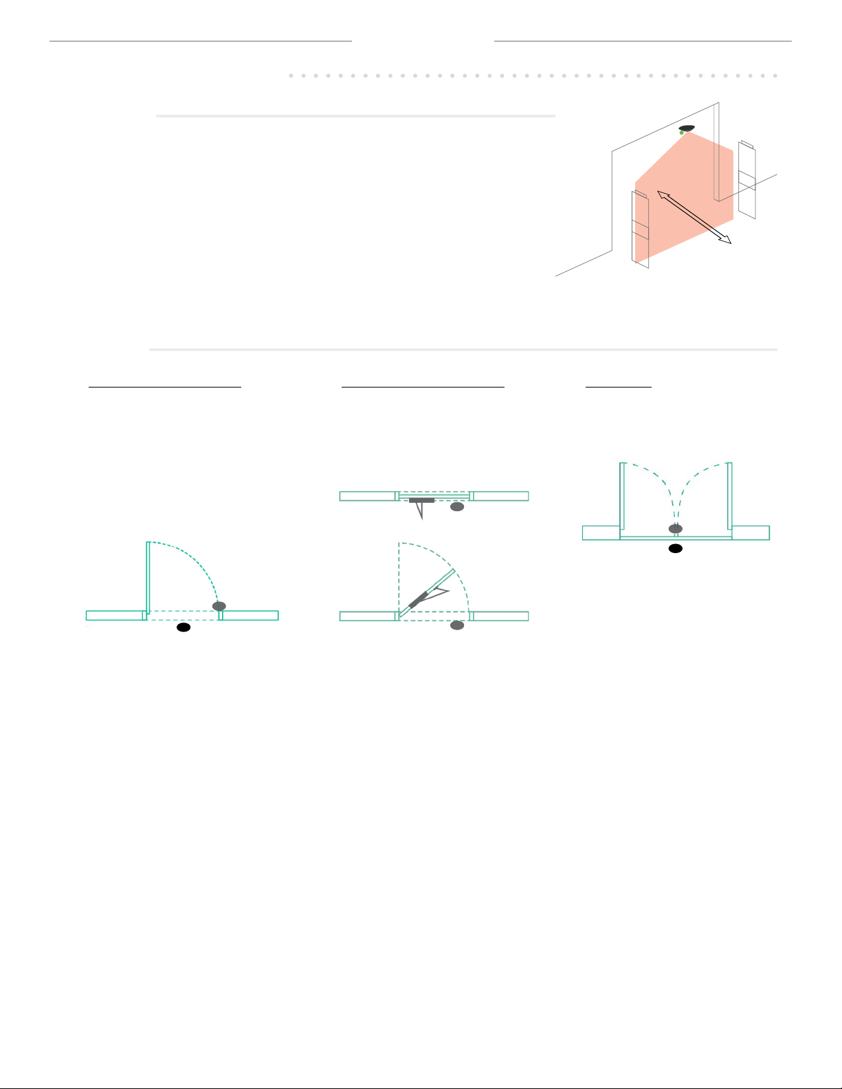
Installation height 7 –18 ft
Counting width coverage Ratio [0.8 - 1.35] depending on mounting height (cf. sizer tool: www.meetsigma.io/sizer/)
Ports 123 NTP (UDP) / 22 SFTP (TCP) / 443 HTTPS (TCP) / 8883 MQTTS (TCP)
Video validation
(optional feature)
Resolution 160px x 120px, frame rate 15 fps
(for counting proof purposes only)
Counting data refresh rate /
granularity 1 min. (granularity 1 min.) to 24h (granularity 5 min.)
Protection degree IP53
Conformity
TECHNICAL SPECIFICATIONS
LED INDICATIONS

©BEA | Original Instructions
75.5929.01 LZR-SIGMA 20210630 Page 4 of 17
HOW IT WORKS
DETECTION
LZR-SIGMA uses laser time-of-ight technology to anonymously
detect people. The sensor precisely measures the shape of an
object passing through the detection zone to create a point cloud.
The point cloud is then analzyed in the sensor to determine if the
object is an adult or child to be counted, or a common object such
as a box, shopping cart, or stroller, and will be not be counted.
A person must cross the invisible detection zone to be detected by
the LZR-SIGMA. The counting data is transferred via the sensor's
network or cellular connection to a destination congured in the
Sensorio portal (sensorio.com).
CAMERA
The built-in camera in the LZR-SIGMA is for verication purposes only - it does not count people or record/transit video
continuously. For instance, if you want to ensure that your sensor is installed appropriately for optimal performance, you
can access the Sensorio portal (sensorio.com) to schedule and review counting proofs recorded by the camera.
The camera was purposely designed to record low-resolution video to preserve anonymity, and can be masked entirely for
applications in sensitive areas.
HOW TO CONNECT –POWER
HOW TO CONNECT –NETWORK
• IEEE802.3af compatible PoE switch or injector
• 24 VDC (±10%) power supply (p/n 08.0829)
LZR-SIGMA models:
• cellular (automatic connection)
• ethernet
LZR-SIGMA-ETH models:
• ethernet
ETHERNET INFORMATION:
When connecting via ethernet, ensure that the local network is set up
correctly to allow the LZR-SIGMA to connect to the Sensorio portal.
Ports 123 (UDP), 22 (TCP), 443 (TCP), and 8883 (MQTT) must be open.
The following sites must be accessible:
SFTP (Port 22)
sftp://drop.sensorio.com/upload
sftp:// 13.80.21.238/upload
HTTPS (Port 443)
https://callback.sensorio.com
http://httpbin.org/post
https://www.sensorio.com/
MQTTS (Port 8883)
eu.airvantage.net

©BEA | Original Instructions
75.5929.01 LZR-SIGMA 20210630 Page 5 of 17
INSTALLATION
BEA, Inc. recommends that you prepare for your installation to avoid unexpected hurdles while on the job.
1. Identify all of the entryways that will require sensors for counting coverage.
2. Review the environment of each entryway (using the following BEA mounting recommendations) to strategize sensor
placement.
a. Identify any obstructions to the detection zone (i.e. laser eld).
b. Identify any objects in/near the detection zone that could aect the ow of trac. Objects such as garbage
bins, sanitizer stations, magazine racks, or end caps can cause trac to stop within, stall within, and straddle the
detection zone, leading to a higher rate of miscounts. If possible, such objects should be moved away from the
entrance to improve counting accuracy.
c. Understand your minimum and maximum installation height.
• MAXIMUM HEIGHT: BEA, Inc. recommends that the sensor be installed at the maximum available height (no
higher than 18 ft) for the best accuracy. If the detection zone is too wide at the maximum available height, it
can be narrowed using the LZR-SIGMA mobile app.
• MINIMUM HEIGHT: To understand your minimum installation height (no lower than 8 ft) , you must rst know
the width of your desired detection area. Once the desired coverage is identied, check the chart below to
reveal your minimum installation height. You can also visit www.meetsigma.io/sizer to use the LZR-SIGMA
sizer tool to calculate minimum installation height.
• CONNECTED SENSORS: If you have reached your maximum available mounting height, but the detection
zone is not wide enough, your application will require the installation of multiple sensors to achieve a
wider detection zone (see Application Note 78.6034 for more information on installing multiple sensors).
To determine the recommended number of sensors to use for your desired detection zone, visit www.
meetsigma.io/sizer to use the LZR-SIGMA sizer tool.
d. Identify your power supply (location of outlets, DC supply, PoE network drops, etc).
e. Verify connectivity –network drop (ethernet) or cellular availability. To verify, power up the sensor and check that
the blue LED is illuminated.
INSTALLATION PREPARATION
MINIMUM INSTALLATION HEIGHT
THRESHOLD
WIDTH ≤40" ≤ 45″ ≤ 50″ ≤ 55″ ≤ 60″ ≤ 65″ ≤ 70″ ≤ 75″ ≤ 80″ ≤ 85″ ≤ 90″
MINIMUM
HEIGHT 90″ 93" 96″ 99″ 102″ 105″ 108″ 111″ 114″ 117″ 120″

©BEA | Original Instructions
75.5929.01 LZR-SIGMA 20210630 Page 6 of 17
INSTALLATION
INSTALLATION PREPARATION
UNSURE ABOUT YOUR APPLICATION? EMAIL BEA FOR A GUIDED INSTALLATION!
If your application has many nuances to be considered that makes you question sensor placement, BEA is here to help.
Before contacting BEA, please be sure to take photographs of the entryway in question - the more, the better!
Helpful tips for photos:
• Wide view of the immediate environment to show the ow of trac and any objects that could aect the ow.
See Figure 1.
• Angles to show depth of any obstructions above the entryway (e.g. air curtains, door hardware). See Figure 2.
Once you have all of your pictures, please email BEA at [email protected] to request a guided installation!
In your email, please include a detailed description of the intended application, what company you purchased your sensor
from (direct from BEA or other), attach your photos, and leave your contact information.
BEA will be in touch to schedule a guided installation!
FIGURE 1 FIGURE 2

©BEA | Original Instructions
75.5929.01 LZR-SIGMA 20210630 Page 7 of 17
HOW IT WORKS
INSTALLATION LOCATION TIPS
Scan
me to
start
X0006F
A
Detection area (location)
The threshold (i.e. counting area) should be appropriately covered. Measure the
desired threshold width across the space in front of the entrance (this is the space that
people will walk through). Beware of creating detection zone that is too wide, as you
could mistakenly be set up to count more than what is intended.
Sensor directionality
Observe the "A" and "B" markings on the sensor.
When wall mounting (or ceiling mounting near a wall), direction A must be pointing away
from the wall.
Proximity to door
The sensor should always be center-mounted above the desired detection zone (exception:
See Swing Doors section), and as close to the entryway as possible while avoiding
obstructions (ideally, no more than 12" from the threshold).
Corridor mounting
When the application calls for mounting in a corridor or hallway, you may
mount away from the door as long as the entire width of the corridor can be
covered by the laser eld.
TOP VIEW
ENTRANCE
max 12"
H
W

©BEA | Original Instructions
75.5929.01 LZR-SIGMA 20210630 Page 8 of 17
HOW IT WORKS
INSTALLATION LOCATION TIPS
Sensor angle
Mount perpendicular to the ow of foot trac.
Swing doors
closing side
1
2
closing side
1
2
closing side
closing side
Single leaf (no door closer):
When possible, install SIGMA on
the closing side in the middle,
outside the swing path (option 1).
When that is not possible, you can
install SIGMA on the opening side.
Make sure you place it right above
the leading edge (option 2).
Double leaf: Install SIGMA in
the center. Preferred side is the
closing side, outside the swing
path (option 1).
Single leaf (with door closer):
If a door closer is obstructing the
view, simply oset the mounting
location nearer to the leading
edge.

©BEA | Original Instructions
75.5929.01 LZR-SIGMA 20210630 Page 9 of 17
INSTALLATION
MOUNTING OPTIONS
BEFORE YOU BEGIN
LZR-SIGMA can be mounted in 3 ways:
• surface-mounted to the ceiling
• recessed into the ceiling
• surface-mounted to a wall
See following page for mounting instructions.
WALL SURFACE-MOUNT
CEILING RECESSED-MOUNTCEILING WALL-MOUNT
The Mini Bracket (10MINIBRACKET) can also be used in applications that will require the
sensor to extend from the wall to avoid obstructions.
See User's Guide 75.5799 for more information.
BEA highly recommends downloading the LZR-SIGMA mobile app and registering your account before you
begin the mounting process.

©BEA | Original Instructions
75.5929.01 LZR-SIGMA 20210630 Page 10 of 17
INSTALLATION
MOUNTING
6. Secure the base to the ceiling.
5. If necessary, a piece of the base can be removed
with a cutting tool.
"CLICK"
4. Pass the cable through the base.
3. Remove the counting head by unclipping it.
Caution – Do not
open the counting
head as it may
result in hazardous
radiation exposure.
Scan
me to
start
X0006F
8. Connect the cable to the counting head
Clip the counting head to the base and close SIGMA.
"CLICK"
"CLICK"
CLASS 1
LASER PRODUCT
7. Or use BEA’s wall mounting accessory to
secure to the wall.
1. Open SIGMA. 2. Determine directionality (see page 7).
Scan
me to
start
X0006F

©BEA | Original Instructions
75.5929.01 LZR-SIGMA 20210630 Page 11 of 17
SETUP
Before beginning the setup process, you must enter data about the sensor you will be programming.
Log in to the LZR-SIGMA mobile app and follow instructions.
Enter the full name of the
company where the sensor is
being installed.
Choose if the sensor is installed
above an area where there will be
swing door movement.
Enter a unique description of the
entryway or choose from a list of
frequently used descriptions.
Identify the site (usually a store
number or location name).
Begin typing the address and a list will
autopopulate with locations. Choose
from an option within the list.

©BEA | Original Instructions
75.5929.01 LZR-SIGMA 20210630 Page 12 of 17
SETUP
Now that all of the applicable sensor information has been entered, continue to follow the prompts in the app to guide
you through the sensor setup.
One sensor = NO
Multiple sensors = YES, see Application
Note 78.6034 for more information
Allow the sensor to learn the eld.
At this step, the sensor is learning the
height and will set left and right limits
according to the maximum allowed
width based on mounting height.
You may manually adjust left and
right limits by simply clicking the edit
button beside the given dimension.
Verify that the learned height is
accurate. If not, see Troubleshooting.
MANUAL ADJUSTMENT (preferred): Measure the width of the entryway and increase or decrease
limit accordingly using the + and - buttons. BEA recommends adding 6" to your dimensions to ensure
your area is fully covered.
AUTOMATIC ADJUSTMENT: Follow prompts.
Be sure to press CONFIRM
when nished.

©BEA | Original Instructions
75.5929.01 LZR-SIGMA 20210630 Page 13 of 17
SETUP
The following three screens are optional and do not aect the performance of the sensor. They are for troubleshooting
and data collection purposes only.
Choose the application type from
the list.
Choose the environment type
from the list.
Choose the entrance type from
the list.
H12345
Once setup is complete, perform a manual counting
proof to verify that your sensor setup is satisfactory.
See next page for information on counting proofs.

©BEA | Original Instructions
75.5929.01 LZR-SIGMA 20210630 Page 14 of 17
ADDITIONAL FEATURES
After the sensor has been set up, this
screen will appear when you connect
to the sensor.
Choosing SET DEVICE INFORMATION
will guide you through the sensor
information setup. See page 11 for
full run-through of screens.
Choosing SET DEVICE NETWORK will
display the information regarding the
network that the sensor is connected to.
CAUTION: These settings should
only be modied by the site network
administrator.
Choosing SET COUNTING AREA
will guide you through the laser
eld setup. See page 12 for full
run-through of screens.
Choosing COUNTING PROOF will allow
you to perform a manual check to verify
that the device is counting properly and
that setup was successful.
Choosing RESET DEVICE will give
options for performing a full reset or
partial reset.
Partial = clears only eld limits
Full = clears all, including sensor
information

©BEA | Original Instructions
75.5929.01 LZR-SIGMA 20210630 Page 15 of 17
INSTALLATION VERIFICATION
Once the sensor setup is complete, perform a nal check of the detection area to ensure that the sensor is installed and
programmed properly.
1. Perform a manual counting proof using the LZR-SIGMA mobile app, and walk straight through the detection area, both
ways, covering the entire detection area (see pattern below). Be sure to manually count yourself in the app each time
you cross the threshold.
Review the manually counted number against the sensor-counted number and determine if obstructions are aecting
sensor performance or if the sensor mounting orientation is incorrect (see page 6, Sensor Directionality).
1
3 2
4
2. Perform another manual counting proof and walk at an angle through the detection zone, entering on the edges of
the detection zone.
Review proof and determine if limits need widened. BEA recommends widening by 6" increments. Review proof and
determine if obstructions are aecting sensor performance or if the sensor mounting orientation is incorrect (see
page 6, Sensor Directionality).
If the results of the manual counting proof are below 90%, contact your integrator to
schedule a video proof via the Sensorio portal for further investigation.

©BEA | Original Instructions
75.5929.01 LZR-SIGMA 20210630 Page 16 of 17
TROUBLESHOOTING
PROBLEM SYMPTOM SOLUTION
White LED
No internet connection The ethernet conguration is wrong or no cellular network is
available
Check the network connection
Check if port 8883 is opened
Orange LED on
Error If this occurs, please contact BEA.
Orange LED ashing
Updating Connection to the device is impossible
Wait for update completion
Orange and white LEDs ashing
At least one of the following port is
not opened:
123 (UDP) / 22 (TCP) / 443 (TCP) /
8883 (MQTTS)
Check network settings with your IT support
See page __ for more information on connecting.
Incorrect height after learn Detection zone obstructed Clear obstructions. If clear, manually adjust the height.
Incorrect sensor orientation (laser
eld hitting the wall)
Verify that the sensor is mounted so that the "A" side of the
sensor is pointing away from the wall.
Sensor tilted towards wall, eld not
reaching oor
If you are able to access the Sensorio
portal, you can check the line position
on a snapshot or from a video
counting proof.
Fix the wall mount by tightening top screws and/or loosening
the bottom screw.
Conrm that the A side of the sensor is pointed away from
the wall, and tighten the tilt screw to move the detection eld
farther away from wall.
If the tilt screw does not solve the issue, insert a shim at the
base of the wall mount accessory to increase the tilt more.
Learned height less than actual
mounting height
Sensor mounted above the
maximum height limit
Lower the mounting height to within recommended limits (8 –
18 ft). If not possible, higher mounting heights are acceptable,
but beware that people less than 4 feet tall may not be counted.
Inaccurate counts (multiple
symptoms could be present)
Sensor mounted above the
maximum height limit
Lower the mounting height to within recommended limits (8 –
18 ft). If not possible, higher mounting heights are acceptable,
but beware that people less than 4 feet tall may not be counted.
Detection eld obstructed Check to see if missed counts are occurring in one area of the
eld. Perform a manual counting proof if necessary. Clear any
obstructions from this area.
If unsuccessful, contact integrator to schedule and review a
video counting proof to further investigate.
Incorrect sensor orientation
(detection eld hitting the wall)
Verify that the sensor is mounted so that the "A" side of the
sensor is pointing away from the wall.
Limits set too small, causing
miscounts on edges of eld
Check to see if missed counts are occurring on the edges of the
eld. If so, increase the limits (recommended: at least 6" wider
than entryway on each side).
Limits set too wide and the sensor
counts because of activity at the
edges of the eld
Check to see if false counts are occurring on the edges of the
eld. If so, decrease the limits (recommended: no more than 6"
wider than entryway on each side).
Sensor too far from entryway and
the sensor misses counts
Check to see if false counts are occurring due to people walking
around the detection eld.
• Choose a new mounting area
• Increase the limits as much as possible
• Place a barrier near the edges of the eld to redirect the ow
of trac back through the detection eld.
If your problem persists, contact your integrator for further investigation.

©BEA | Original Instructions
75.5929.01 LZR-SIGMA 20210630 Page 17 of 17
APPENDIX: SENSOR LOG
When installing multiple sensors at one site, It is considered best practice to log each sensor and its location.
Please use the log chart below by adhering the extra sticker (loose in box) in the appropriate space and log the
site location.
QR code
Site location
QR code
Site location
QR code
Site location
QR code
Site location
Other manuals for LZR SIGMA
1
Table of contents
Other BEA Accessories manuals

BEA
BEA Halma PBS45 Series User manual

BEA
BEA MAGIC SWITCH CHROMA User manual

BEA
BEA WIZARD II User manual

BEA
BEA CONDOR User manual

BEA
BEA MS21H User manual

BEA
BEA MAGIC SWITCH MS21H User manual

BEA
BEA BODYGUARD-T User manual

BEA
BEA FALCON DR User manual

BEA
BEA MW6 User manual

BEA
BEA LZR-WIDESCAN User manual
Popular Accessories manuals by other brands

schmersal
schmersal RSS260 Operating Instructions Supplementary Sheet

PCB Piezotronics
PCB Piezotronics 200C20 Installation and operating manual

camry
camry Premium CR7418 user manual

DeLOCK
DeLOCK 11497 user manual

Swisher
Swisher PowerBlade PBH-1540 Assembly instructions

miniland
miniland NATURMEAL ON-THE-GO manual