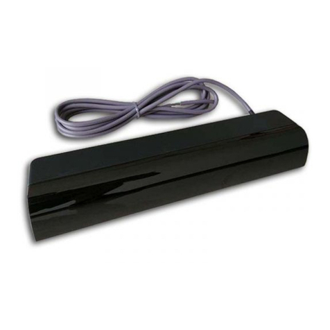
BEA WIZARD-C User manual

75.5101 V1 Sep. 2003 [Rev. 9/22/2003] Page 1 of 16
COMBINED
SAFETY &
ACTIVATION
SENSOR
TECHNICAL
SPECIFICATIONS
USERS GUIDE WIZARD-C
COMBINED ACTIVATION & SAFETY SENSOR
PRELIMINARY
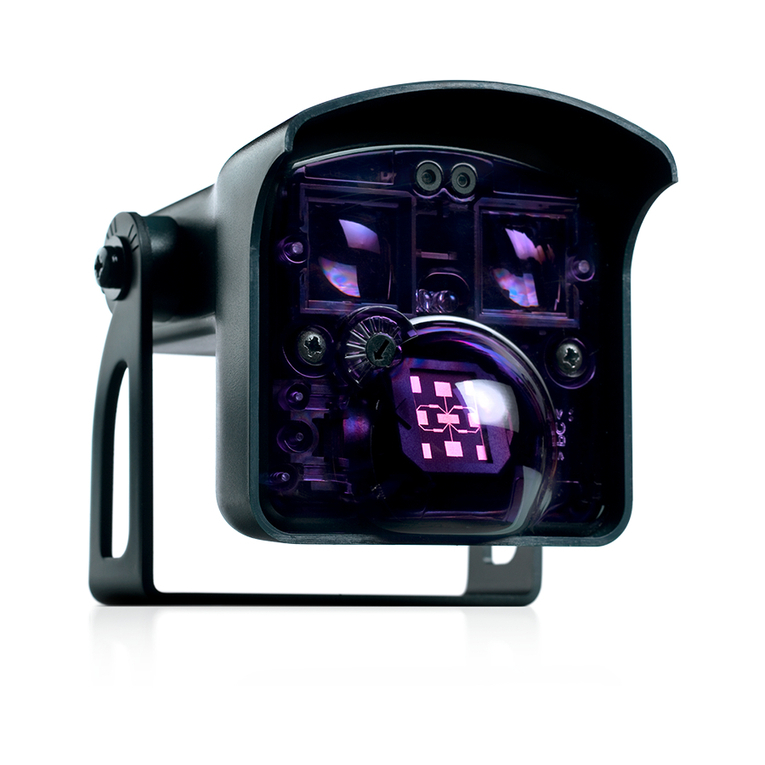
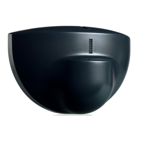
The Wizard-C (PN:10WIZARDC) combines k-band microwave and focused active infrared technology to provide superior
activation and safety for an automatic sliding door system. For activation, the unit provides digitally processed and sophisticated
motion tracking technology for unidirectional sensing when energy conservation is critical. For safety, the unit emits 2 rows of 24
beams of focused presence technology that provides extraordinary safety. The active infrared remains active even when the door
is closing. Serial numbers 52000 and greater provide the added ability for an “ALL RELAY” output, making it compatible with older
non-microprocessed control boxes.
DESCRIPTION SPECIFICATION
Supply voltage 12 to 24 VAC / VDC: -5% to +10%
Power frequency 50 / 60 Hz
Power consumption < 3 W
Mounting height
•Standard
•High
5’9” to 8’2”
8’2” to 13”
SMR data input 10 to 30 V DC
Delay of the output activation after stimulation transistor : < 1ms
3-color LED •RED : presence detection
•GREEN : motion detection
•ORANGE :monitoring process
Temperature range -30°F to +131°F
Degree of protection NEMA 3S / (IP54)
Product conformity R&TTE 1999/5/EC & EMC 89/336/EEC
BZT Germany, TÜV
Dimensions 10.4 " x 2.2 " x 1.9 "
Weight .55 lbs / 250 g
Housing material ABS & LURAN S
Color of Housing Anthracite gray (standard), aluminum or white finish
Cable length 8’ of six-conductor cable
MOTION SENSOR PRESENCE SENSOR
Technology Microwave and microprocessor
Transmitter frequency :24.125 GHz
Transmitter radiated power : <20 dBm EIRP
Transmitter power density : < 5 mW/cm²
Focused active infrared and
Self-monitored microprocessor
Spot diameter (standard) : 4” max
Number of spots : 24 or 12 spots by
curtain
Number of curtains : 2
Detection field (standard)
•Wide field
•Narrow field
13’0” W x 6’6” D
6’6” W x 8’2” D
6’6” W x 13.75” D
3’3” W x 13.75” D
Detection mode Minimum detection speed
2 inches / sec. (measured in the sensor axis)
Response time : < 128ms
Angle : from 15° to 50° in elevation (adjustable) from - 4° to + 4° (adjustable)
Output specification Relay (free of potential change-over contact) :
•Max contact voltage : 42V AC/DC
•Max contact current : 1A (resistive)
•Max switching power : 30W (DC) / 60VA (AC)
Transistor (optocoupled transistor)
•Max output current : 100 mA
•Max switching power : 48 V DC
Output hold-time 0.5s to 9s (adjustable) 1s (fixed)
Manual adjustment •orientation of sensing field (mechanically)
•shape of the sensing field (choice of antenna)
•multiple functions (using push buttons).
•orientation of sensing field
•shape of the sensing field (choice of
front lens)
•multiple functions (by push buttons).
Remote control adjustments •Sensitivity.
•Hold time.
•Detection mode.
•Immunity
•Output configuration.
•Sensitivity.
•Auto-learn time
•Monitoring mode
•Number of Curtains
•Relay / Transistor configuration
•Rain Mode
•Snow Mode
We open up New Horizons
OBSOLETE

75.5101 V1 Sep. 2003 [Rev. 9/22/2003] Page 2 of 16
SAFETY
PRECAUTIONS
MECHANICAL
INSTALLATION
COMPONENT ID
ESD PRECAUTION
(ELECTRO-STATIC
DISCHARGE)
• Shut off all power going to the header before attempting any wiring procedures.
• Maintain a clean & safe environment when working in public areas.
• Constantly be aware of pedestrian traffic around the door area.
• Always stop pedestrian traffic through the doorway when performing tests that may result in unexpected
reactions by the door.
• Always check placement of all wiring before powering up to insure that moving door parts will not catch any
wires and cause damage to equipment.
• Ensure compliance with all applicable safety standards (i.e. ANSI A156.10) upon completion of installation.
1. Remove the cover from the unit as shown in picture “A”. After the Wizard is attached to the header, the
cover may be removed by inserting small screwdriver behind the Wizard and gently prying cover off as
shown in picture “B”.
2. Attach mounting template to the center of header as shown (C) – template should be 0”-2” above bottom
edge of header. Drill the hole marked for wire passage and drill pilot holes for screw mounting (D).
NOTE: Flush mount with bottom of header is necessary for for all neagtive IR angles.
3. Insert mounting screws about halfway in (F shown on next page), and install the Wizard onto the
screws. When in place, tighten screws to secure to header. Leave cover off until mechanical
adjustments are complete.
A
B
CABLE
COVER
MOUNTING SCREWS
MOTION SENSOR
FRONT LENSES
I.R. REMOTE RECEIVER
PRESENCE SENSOR
LED INDICATOR
MANUAL SET-UP
BUTTONS
2n
d
ANTENNA STORAGE
D
0-2”
BOTTOM OF DOOR HEADER
C
WIZARD MOUNTING
TEMPLATE
Circuit board components are vulnerable to damage by electrostatic discharge (ESD). ESD can cause
immediate or subtle damage to sensitive electronic parts. An electrostatic charge can build up on the
human body and then discharge when you touch a board. A discharge can be produced when walking
across a carpet and touching a board, for example. Before handling any board, make sure you
dissipate your body’s charge.
CAUTION: In the event a unit needs to be opened, observe the following precautions.
• Ground yourself by touching a conductive surface of the door or other element connected to common earth ground to discharge
the static electricity present in your body.
• Avoid walking around while replacing items inside the case, especially if you are on carpet or during conditions of low
temperature and low humidity.
• Handle the board by the edges only to avoid touching electronic components.
•
Store a loose board in an anti
-
static bag.
OBSOLETE

75.5101 V1 Sep. 2003 [Rev. 9/22/2003] Page 3 of 16
ELECTRICAL
INSTALLATION
ELECTRICAL
INSTALLATION –
WIRING
1. With Wizard in place, locate the enclosed cable and feed the stripped end through the wire passage
hole in header from the Wizard side as shown in Picture (F). Leave enough slack to allow connection
to the Wizard and proper routing of wire around the plastic posts (E). Please observe proper routing
of the cable as shown – this is to divert rainwater from the Wizard if it should run down the cable, and
also provides for proper routing to allow easy cover installation on the Wizard.
Perform the following for wiring the Wizard to an automatic door control:
Wizard Wire
Color
Connect To:
Microprocessed Controls
Connect To:
Old Style Controls
Red 12 to 24 VAC / VDC: -5% to +10% 12 to 24 VAC / VDC: -5% to +10%
Black 12 to 24 VAC / VDC: -5% to +10% 12 to 24 VAC / VDC: -5% to +10%
White Common at Door Control Common at Door Control
Green Activation Input at Door Control Activation Input at Door Control
Brown Common at Door Control
Blue Safety Input at Door control
Brown & Blue wires are not used for SN
52000 and greater – Do NOT Connect
Them To Anything:
All output is through the white and green
wires. The Wizard MUST be programmed
to a Relay Configuration value of 5 or 6.
See Page 8. Wizards below SN 52000 will
still require a 10IFBWIZARD.
Other Wiring Notes:
1. When connecting to a microprocessed control box, the Motion output and presence output wires may
be connected to separate inputs or may also be to a mutual input, as some controls may only have
an activation input, while others may have an activation input, as well as a safety (or presence) input.
For example:
FOR CONTROLS WITH ONLY AN ACTIVATION INPUT:
Two options exist for this configuration. First the White and Green may be connected to Brown and Blue
(respectively), OR the Relay Configuration may be set to a value of 5 or 6, in which case ONLY the White
and Green wires are used.
OR
2. If separate outputs are available at the control box, White and Green may go to common and activation,
while Brown and Blue will go to the safety (or presence) input. Always respect polarity with Brown and Blue.
Wire fed
through
towards
control
FE
Plastic post
to wrap wires
around
WIZARD
Red - 12 to 24 VAC / VDC: -5% to +10%
Black - 12 to 24 VAC / VDC: -5% to +10%
White – Common at Door Control
Green – Activation at Door Control
Brown
Blue
WIZARD
Red - 12 to 24 VAC / VDC: -5% to +10%
Black - 12 to 24 VAC / VDC: -5% to +10%
White – Common at Door Control
Green – Activation at Door Control
Brown – Not Used
Blue – Not Used
For SN 52000 and greater,
program the Wizard to Relay
Configuration Value 5 or 6. If
set to 5, contacts close upon
detection. If set to 6,
contacts open upon
detection.
+
WI ZAR D
MOUNTING
TEMPLATE
OBSOLETE

75.5101 V1 Sep. 2003 [Rev. 9/22/2003] Page 4 of 16
MECHANICAL
ADJUSTMENTS
MECHANICAL
ADJUSTMENTS
MOTION SENSING
FIELD
1. The position of the sensing field is determined by the vertical angle of the planar antenna. The angle is
adjusted in 3°increments by gently rotating the antenna forward or back. The default mounting angle is 30°-
Patterns shown in diagram below are those at 30°.
2. The tilt angle will be greatly determined by the position of the sensor with relation to the face of the door. A 15º
angle will result in the pattern being drawn back towards the door, where as the 45º will place the pattern
farther away. Be certain to walk-test detection field and insure compliance with current applicable ANSI
standards.
1. Insert the desired microwave planar antenna for a narrow or wide field of detection. Refer to the
diagram below for approximation of field size for each pattern.
7’-0” height = [13’ (W) X 6’ 6” (D)] [6 6” (W) X 8’ 2” (D)]
• The optional narrow-field antenna is located in a slot behind the mounted antenna as shown.
• To remove the antenna, carefully remove the protective cover and change antenna.
• Once proper antenna is in place, adjust angle of antenna as necessary.
WIDE NARROW
6.4’ 3.2’ 0 3.2’ 6.4’
0
3.2’
6.4’
9.6’
Wide Pattern
Narrow Pattern
OBSOLETE

75.5101 V1 Sep. 2003 [Rev. 9/22/2003] Page 5 of 16
BEA’S
UNIVERSAL
REMOTE
CONTROL
MECHANICAL
ADJUSTMENTS
PRESENCE
SENSING FIELD
1. Install the desired lens for the infrared curtain (presence), as shown below.
• Narrow Lens is suitable for smaller door openings or high mounting height applications.
Narrow-field Len
s
Wide-field Lens
[3’3” (W) X 13.75” (D)] [6’ 6” (W) X 13.75” (D)]
2. The infrared presence pattern may be adjusted in two different ways:
• First, the pattern may be adjusted nearer or farther from the door.
• Second, the pattern width may be adjusted to suit the particular door application
3. The adjustment screw will bring the pattern nearer or farther from the face of the door by adjusting the tilt
angle from +4° to –4°. At the standard mounting height, one complete clockwise turn of the adjustment
screw will move the pattern approximately 3 inches closer to the door. The precise location of the infrared
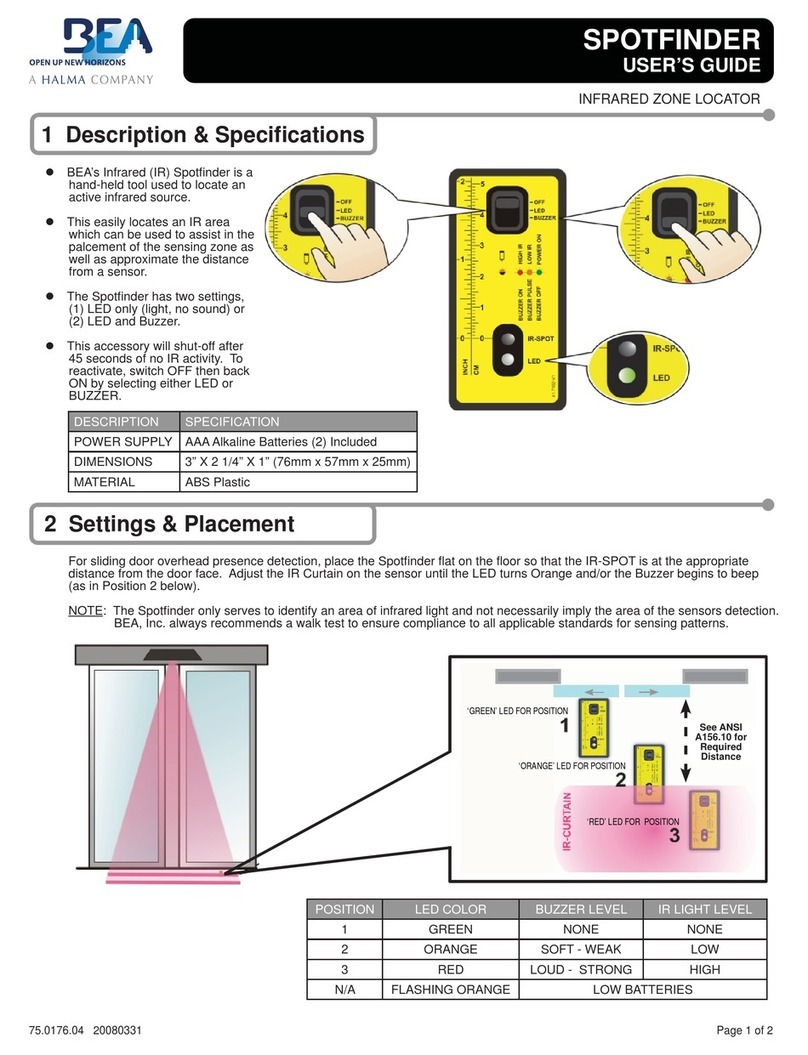
beam may be found by using the BEA Spot-finder (PN: 10SPOT) after the Wizard has been powered up.
•
Open the battery compartment at the
back of the remote control.
• Insert 2 AAA batteries – observe polarity
• Close battery compartment
DOOR
HEADER
-4°+4°
Unlock
Number keys
Radar Sensitivity
Immunity
Radar Detection mode
Check Values
Output Configuration
A
uto-learn time
Curtain Set-up Launch
Choice of Radar Mount Ht.
Default Value
Infrared sensitivity
Lock
- Key
+ Key
SMR
F1
Relay hold time
F2
IR Curtain
-4
+4
OBSOLETE

75.5101 V1 Sep. 2003 [Rev. 9/22/2003] Page 6 of 16
WIZARD SMR
PROGRAMMING
GUIDE – LOCKING
& UNLOCKING
WIZARD SMR
PROGRAMMING
GUIDE – INQUIRE
ABOUT SETTINGS
WIZARD SMR
PROGRAMMING
GUIDE
All program changes and inquiries can only be accomplished while the Wizard is unlocked.
UNLOCK
LOCK
0-9 0-9 0-9 0-9
Press the UNLOCK key once, then enter
your 4-digit code to unlock the Wizard.
0000 The red LED will flash quickly after
UNLOCK is pressed once. After
entering the valid code, Wizard will
flash red LED slowly.
If access code is set to the factory
default value of 0000, the Wizard will
automatically unlock after the
UNLOCK key is pressed once. The red
LED will immediately begin to slowly
flash red.
KEY USER’S ACTIONS DEFAULT LED STATUS
Press the function key that you desire to
inquire about, followed by pressing the
INQUIRY key.
A
fter pressing INQUIRY, count the numbe
r
of green LED flashes – this corresponds to
the setting.
EXAMPLE:
A
fter pressing a function button, the
red LED flashes quickly. After pressing
the INQUIRY key, the green LED
flashes the number of the current
setting. No green flash will indicate a
setting of 0.
= 7 = Default sensitivity value
When all parameters have been set, press
the LOCK key once. If you wish to enter a
new access code, use the 0-9 number keys
and enter the new 4-digit code within 20
seconds.
If you choose not to enter a new code,
press the LOCK key once more, and the
existing code will be retained. If no key is
pressed within 1 minute, the sensor will lock
with it’s existin
g
code bein
g
retained.
0000
A
fter locking, the red LED stops flashing
and the sensor will no longer be in a
program mode.
= Locked with existing code.
0-9 0-9 0-9 0-9
= Locked with new code that is entered.
7
Sensitivity alters the sensitivity of the motion
field only. Values range from 0 to 9,
minimum to maximum respectively.
0 = Minimum sensitivity
9 = Maximum sensitivity
A
fter pressing the SENSITIVITY key,
the red LED flashes quickly. Afte
r
pressing a number button, the red LED
flashes slowly.
RADAR
SENSITIVITY
CHECK VALUES
RELAY HOLD TIME Relay hold time refers to the hold time on
the output relay of the Wizard. Values range
from 0 to 9, .5 seconds to 9 seconds
respectively.
0 = .5 secs.
1 = 1 sec. to 9 = 9 seconds. 1
through 9 in 1 second increments.
0
A
fter pressing the RELAY HOLD TIME
key, the red LED flashes quickly. Afte
r
pressing a number button, the red LED
flashes slowly.
KEY USER’S ACTIONS DEFAULT LED STATUS
OBSOLETE

75.5101 V1 Sep. 2003 [Rev. 9/22/2003] Page 7 of 16
WIZARD SMR
PROGRAMMING
GUIDE – Cont.
OUTPUT
CONFIGURATION
The Output configuration has 4 possible
output values:
1 = N.O. relay, N.C. transistor
2 = N.C. relay, N.O. transistor
3 = N.C. relay, N.C. transistor
4 = N.O. relay, N.O. transistor
5 = All Relay Output (N.O.)
6 = All Relay Output (N.C.)
4
A
fter pressing the OUTPUT
CONFIGURATION key, the red LED
flashes quickly. After pressing a
number button, the red LED flashes
slowly. (N.O. indicates relay closure
upon detection and power-off would
result in an open relay).
Values 5 & 6 available on SN: 52000
and greater
A
UTO-LEARN The Auto-Learn time enables the Wizard to
adapt to new permanent changes within its
field of detection, after the set time (below)
expires. Once expired, the Wizard will
return to a state of non-detection.
7
0 = 30 seconds 4 = 10 minutes
1 = 1 minute 5 = 15 minutes
2 = 2 minutes 6 = 20 minutes
3 = 5 minutes 7 = 10 seconds
9 = Infinit
y
A
fter pressing the AUTO-LEARN key,
the red LED flashes quickly. After
pressing a number button, the red LED
flashes slowly.
Note: Value 9 (infinity) available on
SN: 60000 and greater
RADAR
DETECTION
MODE
Detection mode offers 3 different levels of
detection: Bi-directional, Uni-directional and
Uni-directional with MTF (motion tracking
feature). MTF allows the Wizard to switch
from uni-directional to bi-directional upon
detection from the normal approach
direction.
3
1 = Bi-directional
2 = Uni-directional
3 = Uni-directional with MTF
A
fter pressing the DETECTION MODE
key, the red LED flashes quickly. After
pressing a number button, the red LED
flashes slowly.
IMMUNITY
(motion)
Immunity reduces the influence of unwanted
disturbances within the field of motion
detection, without reducing the pattern.
1 = Extreme sensitivity
2 = Normal Sensitivity
3 = Reduced sensitivity
2
A
fter pressing the IMMUNITY key, the
red LED flashes quickly. After pressing
a number button, the red LED flashes
slowly.
INFRARED
SENSITIVITY
Infrared sensitivity reduces the influence of
unwanted disturbances within the field of
presence detection.
1 = Low sensitivity – hi gloss floors
2 = Normal sensitivity
1
A
fter pressing the INFRARED
SENSITIVITY key, the red LED flashes
quickly. After pressing a number
button, the red LED flashes slowly.
RADAR
MOUNTING
HEIGHT
0 = launch infrared set-up (learn
background).
1 = Microwave at normal mounting
height
2 = Microwave at high mounting
height (8’ 2” to 13’)
3 = Restore all parameters to
default value. SN less than 52000
9 = Same as value 3, but only for
SN 52000 and greater.
1
A
fter pressing the INFRARED
SENSITIVITY key + 0, the red / green
LED flashes to indicate set-up.
A
fter pressing the INFRARED
SENSITIVITY key + 1, 2, or 3
the red LED will flash slowly.
SMR
SMR (Self-Monitoring Ready) mode is
enabled for the use with BEA’s DCU (Door
Control Unit). It is disabled for all other
applications. The DCU sends & receives
monitoring signals to the sensor when this
feature is enabled. The DCU can then take
control of a door in the event of a sensor
failure.
0 = SMR Input OFF
1 = SMR input ON
0
A
fter pressing the SMR key, the red
LED flashes quickly. After pressing a
number button, the red LED flashes
slowly.
KEY USER’S ACTIONS DEFAULT LED STATUS
OBSOLETE

75.5101 V1 Sep. 2003 [Rev. 9/22/2003] Page 8 of 16
RAIN MODE
SNOW MODE -
STANDARD
WIZARD SMR
PROGRAMMING
GUIDE – Cont.
RAIN MODE:
1. The Rain Mode is designed to minimize the effect of heavy rain on the Wizard’s auto-learn
requirements. Rain Mode will be enabled after the Wizard goes through two auto-learn cycles within
no more than 6 detection cycles of the sensor between these 2 auto-learn cycles. During Rain Mode,
auto-learn time will remain the same. However, the second infrared curtain will change from IR
presence detection to IR motion detection. This is done to help eliminate unwanted detection of
heavy rain, as well as it’s effects on the ground. The only required setting on the Wizard SMR to
enable Rain Mode is IR Sensitivity, which must be set to a value of 2 (normal). This mode will
automatically expire upon a power reset, or upon expiration of one hour. This mode could be
launched again under the same conditions.
STANDARD SNOW MODE:
The Snow Mode is designed to minimize the effect of heavy snow on the Wizard’s auto-learn requirements.
Snow Mode may only be enabled by performing the following:
1. Using the BEA remote control, Unlock the Wizard as described in the programming guide.
+ unlock code, if necessary.
2. Set Infrared Sensitivity to LOW (1).
+ 1 = Low Sensitivity
3. Set Auto-Learn Time to 30 seconds (0).
+ 0 = 30 second learn-time
4. Lock The Sensor when complete +
5. After the above changes have been made, the Wizard will go into the Standard Snow Mode after it
goes through 2 auto-learn cycles within no more than 6 detection cycles of the sensor between these
2 auto-learn cycles.
6. While in Standard Snow Mode, the auto-learn time will change from 30 seconds to 10 seconds.
This mode will automatically expire upon a power reset, or upon expiration of one hour, as long as
the settings (as outlined above) are in effect. This mode could be launched again under the same
conditions.
DOOR CONTROL
FUNCTION
The Door Control function enables the User
to select a mode of door operation.
1 = Door permanently open.
2 = Door permanently closed – no
detection
3 = Door in automatic mode –
Wizard, upon detection, opens door.
A
fter pressing the DOOR CONTROL
FUNCTION key, the red LED flashes
quickly. After pressing a number
button, the red LED flashes slowly.
3
IR CURTAIN The IR Curtain function allows the User to
toggle the second IR curtain (farthest from
the door) on & off. When the curtain is off, it
operates in a motion sensing mode.
1 = 1 IR curtain (inner) ON.
2 = Both IR curtains (inner &
outer) ON.
2
A
fter pressing the IR CURTAIN
FUNCTION key, the red LED flashes
quickly. After pressing a number
button, the red LED flashes slowly.
IMPORTANT NOTE:
When changing the values of the above parameters to go from one mode to another, one should
force a set-up by remote control, push buttons, or by a power-off / on sequence.
OBSOLETE

75.5101 V1 Sep. 2003 [Rev. 9/22/2003] Page 9 of 16
MANUAL SET-UP
(without remote)
SNOW MODE -
CANADIAN
CANADIAN SNOW MODE (FACTORY SETTING):
The Snow Mode is designed to minimize the effect of heavy snow on the Wizard’s auto-learn requirements.
Snow Mode may only be enabled by performing the following:
1. Using the BEA remote control, Unlock the Wizard as described in the programming guide.
+ unlock code, if necessary.
2. Set Infrared Sensitivity to LOW (1).
+ 1 = Low Sensitivity
3. Set Auto-Learn Time to 10 seconds (7 - FACTORY SETTING)
+ 7 = 10 second learn-time
4. Lock The Sensor when complete +
5. After the above changes have been made, the Wizard will go into the Canadian Snow Mode after it
goes through 2 auto-learn cycles within no more than 6 detection cycles of the sensor between these
2 auto-learn cycles.
6. While in Canadian Snow Mode, the auto-learn time will change from 10 seconds to infrared motion.
This mode will automatically expire upon a power reset, or upon expiration of one hour, as long as
the settings (as outlined above) are in effect. This mode could be launched again under the same
conditions.
• Set-up of the Wizard may be accomplished by the use of two Wizard mounted programming buttons. The
procedures below indicate how to program using these buttons.
• The two set-buttons are located at the right side of the Wizard (as viewed when mounted to header). To
begin, briefly press the right button and move away from the sensing patterns.
TO RESET THE UNIT to factory defaults including the access code.
• Press and hold both buttons simultaneously until both red and green LED lights flash alternately
TO CUSTOMIZE SETTINGS FROM FACTORY DEFAULTS
• To enter the customizing mode: Press the right button until the LED light flashes and then release
• To return to standard mode: Press the right button again until the LED light stops flashing and then release
CUSTOMIZING MODE
• The red LED light indicates the number for the parameter being altered ( 1 flash = parameter #1)
• The green LED light indicates the value for the parameter being altered ( 1 flash means value = 1)
• The right button enables selection of the parameter number being altered ( +1 for each press)
• The left button enables alteration of the parameter ( +1 for each press)
Manual Push-Buttons
IMPORTANT NOTE:
When changing the values of the above parameters to go from one mode to another, one should
force a set-up by remote control, push buttons, or by a power-off / on sequence.
OBSOLETE

75.5101 V1 Sep. 2003 [Rev. 9/22/2003] Page 10 of 16
POWER-UP
PROCEDURES
MANUAL SET-UP
(without remote)
MANUAL SET-UP
(without remote) –
Cont.
PARAMETER NUMBER
(altered by the right button and
confirmed by GREEN LED)
PARAMETER VALUES
(altered by the
left button and
confirmed by
RED LED)
DEFAULT
VALUE
1 Radar Sensitivity 0-9 7
2 Relay hold time 0-9 0
3 Output configuration 1-6 4
4 Auto-learn
presence sensing 0-7 7
5 Detection mode 1-4 3
6 Immunity 1-3 2
7 IR sensitivity 1-2 1
8 Radar mounting
height 1-2 1
9 Not Used -
Must remain at 0 0 0
10 Door control function 1-3 3
11 SMR mode 0-2 0
12 IR curtain 1-2 2
EXAMPLE: Change radar sensitivity from 7 to 9 and set hold time to 4 seconds:
1. Press the right button for 2 settings, you will enter the customizing mode
• The green LED flashes once (parameter 1)
• The red LED flashes 7 times (sensitivity = 7)
• Press the left button twice to move from sensitivity = 7 to sensitivity = 9
2. Press the right button once to move to Parameter 2 (relay hold time)
• The green LED flashes twice (parameter 2)
• The red LED does not flash (hold time = 0 seconds)
• Press the left button four times to move from hold time = 0 to hold time = 4 seconds
NOTE:
1. When the highest value for the parameter has been reached, the value will “roll over” to its lowest value
(e.g. for radar mode: 1, 2, 3, then 1, 2, …).
2. The sensor automatically returns to standard mode if neither button has been pressed for one minute.
STEP 2
With all wiring in place, apply power to door control
and 12 to 24 VAC / VDC: -5% to +10% to Wizard.
Once powered, observe LED status on the Wizard.
Stop all traffic through the doorway while
performing this step, and remain clear of the
Wizard’s detection zones.
STEP USER’S ACTION RESULT
The Wizard will flash a red / green LED during
the set-up procedure. Once the Wizard
completes set-up, the door will close and begin
normal operation thereafter.
STEP 1
Once set-up is complete, the LED indication will
reflect the status of the set-up. Observe the LED
while standing outside of the detection zones.
•
NO LED = Successful set-up
• RED LED ON = Presence being detected -
Wizard is seeing an object.
• RED LED Flashing for 10 seconds. Infrared
curtains are too close to door. Adjust curtains
using the Spotfinder.
• GREEN LED MOMENTARILY ON = MOTION
DETECTION (Wizard sees movement).
• ORANGE LED ON = Wizard is executing a
Self-Monitoring test (only when SMR mode is
enabled). LED should expire in approx. 6
seconds. If LED stays on, reset power and
observe LED. If it comes back on steady,
replace Wizard.
STEP 3 Proceed with fine tuning the mechanical , as well as
the program adjustments of the Wizard. Refer to the
applicable sections of this manual for altering any
settings. Be sure to check:
• Motion width & depth
• Presence width & depth
• Position of infrared curtain
• Sensitivity of motion field
Doors will always be adjusted to be in
compliance with ANSI A156.10
OBSOLETE

75.5101 V1 Sep. 2003 [Rev. 9/22/2003] Page 11 of 16
TROUBLE-
SHOOTING
PROBLEM PROBABLE CAUSE CORRECTIVE ACTION
Wizard will not power up. 1. Faulty power supply. 1. Ensure correct power supply of 12 to 24 VAC
/
VDC: -5% to +10%. Power should come from an
isolated transformer
–
not from the door control
Orange LED is illuminated on
Wizard.
1. Wizard is in self-monitoring
mode
2. Internal fault within the Wizard
3. Faulty Power Input
1. Orange LED should expire after self-
monitoring test is complete (6 seconds). This
occurs every 60 minutes.
2. If SMR is not being used, remove power from
the Wizard and re-apply. If orange LED
illuminates and door will not enter into a set-
up, replace faulty Wizard.
3. Remove power, then re-apply. Input powe
r
may have fluctuated beyond tolerances.
Red LED on at Wizard. 1. Wizard in detection.
1. If red LED is on at Wizard:
a. Adjust infrared pattern away from the door and
launch a new set-up. Refer to page 5 fo
r
infrared adjustments. Use BEA Spotfinder to
accurately adjust the position of the pattern.
b. If hi-intensity lights or high gloss floors are
saturating the area of detection, change the
Infrared Sensitivity setting to reduced
sensitivity – see page 7, and launch a new set-
up to re-learn the environment.
Door keeps recycling open.
Door will not close
Red LED off at Wizard.
1. On-Off switch at door control
in wrong position or is faulty.
2. Improper Relay Configuration
on Wizard.
3. Faulty door control.
1. Check to insure On-Off switch for door is in the ON
or AUTOMATIC position. If switch is in correct
position, check switch with multi-meter for prope
r
operation.
2. Ensure correct polarity at Brown and Blue wires
3. Check Relay Configuration setting on each Wizard.
Refer to page 6 for settings.
4. Remove all sensor inputs from the door control. I
f
door remains open, fault exists with door control o
r
motor. Refer to manufacturer’s manual for furthe
r
troubleshooting. If door closes with sensor inputs
removed, fault exists with sensors or related wiring.
1. On-Off switch at door control
in wrong position or is faulty.
2. Wizard not detecting traffic.
3. Faulty wiring between sensor
and door control.
4. Faulty door control.
1. Ensure that On-Off switch for door is in ON o
r
AUTOMATIC position. If it is in correct position,
check switch with multi-meter for proper operation.
2. Walk in and out of Wizard detection area, if red LED
does not illuminate check:
a. Power supply for Wizard: 12 to 24 VAC / VDC: -
5% to +10%
b. Check SMR setting on each Wizard. The SMR
should be disabled unless system is being used
with BEA’s Door Control Unit (DCU).
c. Check Relay Configuration for each Wizard. Refe
r
to page 6.
3. Remove all sensor inputs from the door control.
Jumper the common and activate terminals of the
door control. If door does not open, fault lies within
door control or motor. Refer to manufacturer’s
manual for further troubleshooting. If door opens,
fault lies with sensors or related wiring.
4
Refer to Step 3
1. Wizard is seeing door.
2. Wizard is seeing movement from
unwanted objects.
3. Vibration is triggering the Wizard.
1. Observe LED status on each Wizard. Green LED
indicates motion detection, red LED indicates
presence. If LED’s are illuminating make senso
r
adjustments as necessary to eliminate unwanted
detection. Check angle and sensitivity for presence
and motion.
2. Check for moving objects in the path of detection,
such as posters, banners, etc.
3. Locate source of vibration and correct as necessary.
Door opens when it should
close. 1. Relay Configuration on wrong
setting.
1. Check Relay Configuration setting. Refer to page 6.
Door will not open.
Red LED flashes for approx.
10 seconds when attempting a
set-up.
1. Infrared curtains are too close to
the door and the sensor detects a
door influence.
1. Adjust Infrared curtain as necessary. Use of BEA’s
S
p
otfinder durin
g
this
p
rocess is recommended.
OBSOLETE

75.5101 V1 Sep. 2003 [Rev. 9/22/2003] Page 12 of 16
COMPANY
CONTACT
ACCESSORIES
If after troubleshooting a problem, a satisfactory solution cannot be achieved, please call B.E.A., Inc.
for further assistance during Eastern Standard Time at 1-800-523-2462 from 7am - 5pm.
For after-hours, call East Coast: 1-866-836-1683 or 1-800-407-4545 / Mid-West: 1-888-308-8843 /
West Coast: 1-909-596-3011. DO NOT leave any problem unresolved. If you must wait for the following workday to
call B.E.A., leave the door inoperable until satisfactory repairs can be made.
NEVER sacrifice the safe operation of the automatic door or gate for an incomplete solution.
Wizard will not respond to
remote control.
1. Batteries in remote are dead or are
installed improperly.
1. Ensure that the batteries are installed
correctly – observe polarity.
2. Replace batteries - AAA 1.5 volt.
Wizard will not unlock when
access code is entered. 1. Improper code being entered. 1. Reset code to the default value of 0000 b
y
performing one of the following:
a. Press the 2 buttons on the Wizard
simultaneously until the red & green led
begin flashing. This will return ALL settings
to their default value.
b. Cut and restore power supply. No code is
required to unlock during the first minute
after powering. Reset code prior to locking.
Red LED is flashing rapidly
after attempting set-up.
Detection field was violated during set-
up of the Wizard.
1. Launch a new set-up and insure that the
detection field remains all clear until set-up is
complete.
2. Wizard may be seeing the door as it is closing.
Adjust infrared curtain and launch a new set-
up.
PROBLEM PROBABLE CAUSE CORRECTIVE ACTION
TROUBLE-
SHOOTING
- Cont.
• Weather Hood Unit
(10URC)
•
Ceiling Adaptor
(10WCA)
Wizard will not respond to
motion.
Improper SMR setting 1. If the Wizard is NOT being used with a BEA
DCU, set SMR to a value of 0. See page 8.
•
Remote Control
(10REMOTE)
• SpotFinder
(10SPOT)
OBSOLETE

75.5101 V1 Sep. 2003 [Rev. 9/22/2003] Page 13 of 16
ADDENDUM 1 –
WIZARD WITH
STANLEY
DURAGLIDE &
ROTARY SWITCH
The purpose of the addendum is to accommodate for the differences in the Standard Rocker Switch package and the
Rotary Switch package. The standard wiring provided with the Rotary Switch Package is incompatible when using the
partial opening switch selection with the Wizard sensor system.
When using the Stanley Rotary Switch on a Duraglide slider package with a newer style Stanley interface board,
observe the following:
• The brown wire from the Wizard must be connected to terminal #3 (Common) on TB-3 of the interface.
PH:(412)249-4100FAX:(412)249-4101
B.E.A., Inc.
100EnterpriseDrivePittsburgh,PA15275
REV:
1 OF 1
NONE
SIZE:CAGECODE:DWGNO:FILEOF:
GDM
20MAR2002
GDM
A
STANLEYDURAGLIDEWITHWIZARDSYSTEM
TITLE:STANLEYDURAGLIDEWITH
WIZARDSYSTEM
C
NOTES:1)WIZARDSWILLOPERATEWITHTHE12VDCONPINS1&2,5&6.
2)ONEWAYFUNCTIONISAPPLICABLEIFCLOSEDDOOR
MONITORINGSWITCHISINSTALLED.
BROWN
BLUE
BLACK
RED
24 V
TRANSFORMER
115 VAC
TB-2
1
2
3
4
5
6
7
8
BROWN
BLUE
BLACK
RED
WIZARDINTERIOR
WIZARDEXTERIOR
TB-3
1
2
3
4
5
6
7
8
HOLDINGBEAMS
COMMON
EXTERIORSCAN
INTERIORSCAN
COMMON
WHITE
GREEN
WHITE
GREEN
12VOLT
TRANSFORMER
TB-1
TB- 2 TB- 3
DURAGLIDEINTERFACEBOARD
1
2
3
4
5
6
7
8
9
10
1
2
3
4
5
6
7
8
9
10
1
2
3
4
5
6
7
8
9
10
COMMON
80.0123
SHEET:
DRAWNBY:
SCALE:DATE:
OBSOLETE

75.5101 V1 Sep. 2003 [Rev. 9/22/2003] Page 14 of 16
ADDENDUM 2 –
WIZARD WITH
BESAM AMD-II
DWG NOSIZE
SHEETSCALE
CAGE CODE
A
PH: (412)782-5150 FAX: (412)782-5154
B.E.A., Inc.
100 Enterprise Drive Pittsburgh, PA 15275
DATE:
NONE 1 OF 1
FILE OF: DRAWN BY:
KJG
REV
BGDM
24 NOV 2000
TITLE:BESAMCUJ-9AMDSLIDINGDOOR
WITHWIZARDSYSTEM
R
1
2
3
4
5
6
7
8
9
10
11
12
13
14
15
16
EXTERIOR WIZARD
INTERIOR WIZARD
BROWN
BLUE
BLACK
RED
WHITE
BROWN
BLUE
BLACK
RED
GREEN
(+)
(-)
(-)
(-)
Reset
0 VDC
Part. open
Exit
Off
0 VDC
Stop Impulse
Pres. Impulse 1
C-Switch; 0 v
Pres. Impulse 2
18 VDC
0 VDC
Outer Impulse
Inner Impulse
18 VDC
(+)
(+)
PS-6
6
5
4
3
2
1
*
* Optional - connect
to reset (TB1 R) if required.
LOCKING DEVICE
24 VAC
GREEN
WHITE
BESAM CUJ-9 AMD II SLIDING DOOR WITH WIZARD SYSTEM
608
NOTE: 1) DO NOT CONNECT TO C SWITCH COMMON.
2) OBSERVE POLARITY WITH BROWN CONNECTING
TO GROUND (0 VDC).
3) A JUMPER MUST BE INSTALLED IN PINS 9,13 ON
CONTROL BOX FOR RE-ENTRY SENSOR IN
ONE-WAY TRAFFIC AS PER ANSI STANDARD 8.2.3.
OBSOLETE

75.5101 V1 Sep. 2003 [Rev. 9/22/2003] Page 15 of 16
ADDENDUM 3 –
WIZARD WITH
BESAM UNI-SLIDE
GREEN
WHITE
BROWN
BLUE
BLACK
RED
GREEN
WHITE
BROWN
BLUE
BLACK
RED
WIZARD EXTERIOR
WIZARD INTERIOR
24 V
TRANSFORMER
115 VAC
UniSlide Control
16
15
14
13
12
11
10
9
8
7
6
5
4
3
2
1INNER IMPULSE
- 0 VDC
+ 24 VDC
- 0 VDC
OUTER IMPULSE
KEY IMPULSE
SYNCHRONIZING INPUT
SYNCHRONIZING OUTPUT
+ 24 VDC
- 0 VDC
PRESENCE IMPULSE 2
PRESENCE IMPULSE 1
STOP IMPULSE
C-SWITCH/MONITORED INNER IMPULSE
+ 24 VDC
MONITORED SAFETY/ONLY PHOTOCELL
BESAM UNISLIDE SLIDING DOOR WITH WIZARD SYSTEM
SIZE:
SHEET:SCALE:
A
PH:(412)249-4100FAX:(412)249-4101
B.E.A., Inc.
100EnterpriseDrivePittsburgh,PA15275
DATE:
www.beasensors.com
CAGE CODE: DWG NO: FILE OF: DRAWN BY: REV:
1OF1
NTS
Tech Support
80.0163GDMB
11Mar2003
TITLE: BESAM UNISLIDE SLIDING DOOR
WITH WIZARD SYSTEM
NOTE: 1) DO NOT CONNECT BROWN WIRES TO C-SWITCH COMMON.
2) OBSERVE POLARITY WITH THE BROWN WIRE CONNECTED
TO GROUND (0 VDC).
3) A JUMPER MUST BE INSTALLED BETWEEN PINS 5, 12 ON THE CONTROL
BOX TO ALLOW FOR RE-ENTRY SENSOR IN ONE-WAY TRAFFIC MODE TO
COMPLY WITH ANSI A156.10 SECTION 8.2.3.
OBSOLETE

75.5101 V1 Sep. 2003 [Rev. 9/22/2003] Page 16 of 16
ADDENDUM 4 –
WIZARD WITH
DOR-O-MATIC 96K
SLIDER
PH: (412)249-4100 FAX: (412)249-4101
B.E.A., Inc.
100 Enterprise Drive Pittsburgh, PA 15275
DATE:
REV:DRAWN BY:
SHEET:SCALE:
SIZE: CAGE CODE: DWG NO: FILE OF:
JED GDM
A80.0137
1 OF 1NONE 08 JUL 2003
18 PIN
POWER INPUT
120 VAC
WHITE
GREEN
BLACK
GREEN/ YELLOW
RED
RED
96005-900
QUANTUM-SLIDE
TRANSFORMER BOX
B
MORNING ENTRY PINS 15,16
BREAKAWAY PINS 13,14
EXTERIOR ACTIVATE PINS 9,10
SAFETY BEAMS PINS 3,4
WEATHERWISE PINS 11,12
INTERIOR ACTIVATE PINS 1,2
3 OR 4 WAY SWITCH
PINS 5,6,7
LOOK-SEE COM LINE PIN 8
LOOK-SEE OUTPUT PINS 17,18
96010-900
QUANTUM -SLIDE
CONTROL BOX
ACCESSORIES 24 VDC PIN 1(+) PIN 2(-)
ACCESSORIES 24 VAC PINS 3,4
4 PIN
5-PIN
EARTH/GROUND
NEUTRAL
MAIN
3-PIN
RA WH 1
RA BL 2
EA WH 3
EA BL 4
5 NC
4 NO
3 COM
2 12-24 vac/dc
1 12-24 vac/dc
RB WH 1
RB BL 2
EB WH 3
EB BL 4
1 2 3 4
* RECEIVER (A), EMITTER (A)
RECEIVER (B), EMITTER(B)
WH= WHITE, BL= BLACK
MICROCELL ONE
GREEN
WHITE
BLACK
RED
INTERIOR WIZARD
24 V
TRANSFORMER
115 VAC
GREEN
WHITE
BLACK
RED
EXTERIOR WIZARD
TITLE: DOROMATIC 96 K SLIDER WITH
WIZARD, MICROCELL 1 SYSTEM
BROWN
BLUE
BLUE
BROWN
NOTES: 1) OBSERVE POLARITY ON WIZARD PRESENCE OUTPUT
(+) BLUE AND (-)BROWN WIRES. BLUE CONNECTS TO
PIN 3 AND BROWN CONNECTS TO PIN 4 ON THE DOOR
CONTROL.
OPTIONAL
OBSOLETE
This manual suits for next models
1
Table of contents
Other BEA Accessories manuals