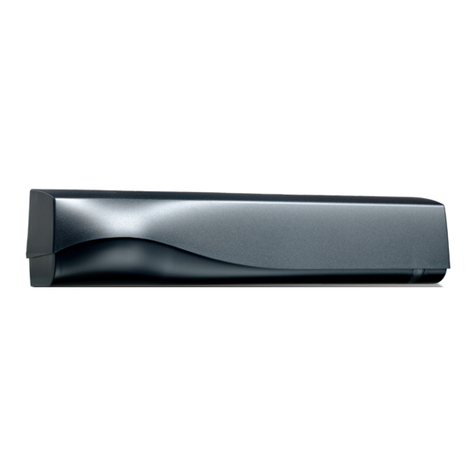
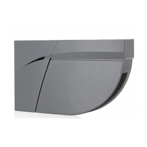
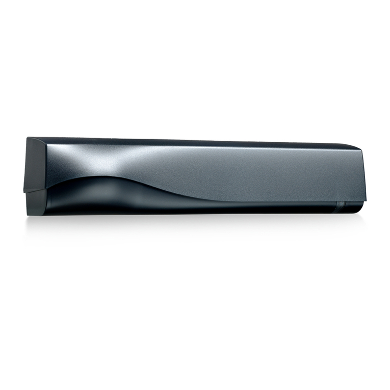
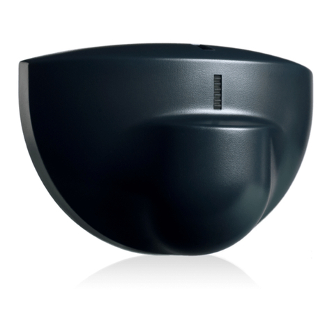
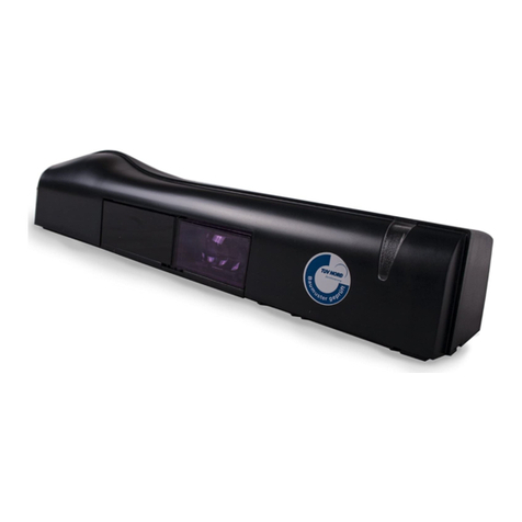
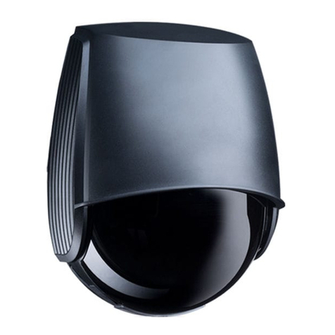
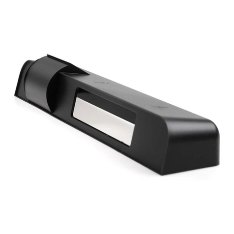
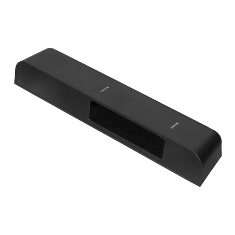
BEA LZR FLATSCAN S User manual

LZR®- FLATSCAN S
EN PLEASE KEEP FOR FURTHER USE - DESIGNED FOR COLOUR PRINTING
1
COMPACT LASER SCANNER
FOR PERIMETER AND WORK OF ART
PROTECTION
User’s Guide for software version SW 0100 and higher
(refer to tracking label on product)

2
3
2
1
4
56
78
INTRODUCTION
The FLATSCAN S is a laser sensor designed for the protection of work of art and other valuables and for the
protection of perimeters.
It generates an invisible curtain with 400 laser beams, which covers the detection area with a high
resolution.
DESCRIPTION
1. Front cover (protective cover)
2. Housing
3. Laser window
4. LED-signal
5. USB connector (only for factory use)
6. Visible laser beams
7. Cable gland
8. Bracket (optional)

3
detection error LED
LED flashes LED is offpower on no power
LED flashes quickly LED flashes slowly
LED-SIGNALS
SYMBOLS
Caution!
Laser radiation
Remote control
sequence
Possible
remote control
adjustments
SAFETY TIPS
The device emits invisible (IR) and visible laser radiations. The visible
laser beams can be activated during the installation process to adjust
the position of the detection field.
Do not stare directly into the visible red beams.
The visible laser beams are inactive during normal functioning.
Factory values Attention Note
Do not stare into the visible
red laser beams.
Only trained and qualified
personnel may install and setup
the scanner.
The warranty is invalid if
unauthorized repairs are made
or attempted by unauthorized
personnel.
CAUTION!
Use of controls, adjustments or performance of procedures other than those specified herein may result
in hazardous radiation exposure.

4
INSTALLATION AND MAINTENANCE
0°C
°C
°C
-10°C
1
Avoid the presence of
smoke and fog in the
detection field.
Avoid condensation.
Avoid exposure to
sudden and extreme
temperature changes.
Avoid direct exposure
to high pressure
cleaning.
Do not use dry or dirty
towels or aggressive
products to clean
the laser window.
Clean the laser window
with compressed air.
When needed, wipe the
laser window only with
a soft, clean and damp
microfibre cloth.
Keep the scanner
permanently powered
in environments where
the temperature can
descend below -10oC.
Avoid extreme
vibrations.
Do not cover the laser
window.
Avoid moving objects
and light sources in
the detection field.
INSTALLATION
MOUNTING
Please do a thorough inspection and evaluation of the installation area to make sure the
sensor's installation will suit the intended use.
Only remove the front cover right before putting the sensor into service.
Make sure the laser window is never covered.
The device cannot be used for purposes other than its intended use, and particularly not the protection of
persons. All other uses than those specified cannot be guaranteed by the manufacturer of the sensor.

5
2 WIRING
BLUE
RED+
BLACK
BROWN
GREEN
GROUNDING
CABLE
-
MONITOR TEST
YELLOW
WHITE
OUTPUT 1(OPTO)
PINK
GREY
VIOLET
OUTPUT 2(RELAY)
+
-
12-24V DC POWER SUPPLY
COM
NC
COM
NO
NC
*
*
Bracket installation (optional):
Prepare the bracket for the
installation.
Fix the Flatscan S to the bracket Choose an appropriate location
and install the sensor on a solid
surface.
* Output status when scanner is operational (Factory default connection)
Since there is no monitoring, the red and blue cables must be connected to the power supply
*2Grounding: make sure that the sensor is correctly earthed.
*2

6
30 minutes after last use, the sensor locks the access to the remote control session.
Cut and restore power supply : the remote control session will be accessible again during 30 minutes.
x
4 2
1
x
teach-in
HOW TO USE THE REMOTE CONTROL
Before using the remote control, please check the following points:
1. The max. distance between the sensor and the remote control is 4 m.
2. The sensor's curtain should not be perpendicular to a high reflective surface. A 3-degree angle is necessary between them
to guarantee communication between the sensor and the remote control.
3. The authorized operator or installer can set a password to avoid unwanted modifications in the chosen settings
After unlocking, the red LED
flashes and adjustments can
be made by remote control.
If the red LED flashes quickly after unlocking, you
need to enter an access code (1 to 4 digits). To end an adjustment session,
always lock the sensor.
ADJUSTING ONE OR MORE PARAMETERS
CHECKING A VALUE
= field width: 4.2 m
X = THE NUMBER OF FLASHES INDICATES THE VALUE OF THE PARAMETER.
RESTORING TO FACTORY VALUES
An access code is recommended for sensors installed close to each other.
SAVING AN ACCESS CODE
DELETING AN ACCESS CODE
After power on, you have 1 minute to choose this setting.
The setting will take effect 1 minute later.

7
SETTINGS
(1)
(2)
(3)
(4)
(5)
(6)
(11) Detection field 1 (W)
(12) Detection field 1 (H)
(13) Detection field 2 (W)
(16) Check Values
(17) Lock
(18) Output configuration
(20) Multifunction key * 2
(7)
(8)
(9)
(10)
(14) Detection field 2 (H)
* 1
(15) Uncovered zone
(19) Antimasking & Background
(21) Immunity filter
(22) LED activation
Visible spot - alignment
Laser beam - detec�on
0-9 Number keys
Detection field
Redirection
Plus
Unlock
Minus
Output activation delay
Min. object size
Detection area activation
Mounting side
Fog filter
* 1. Mounting side: right
* 2. Match with other keys to change among different
functions
VISIBLE SPOTS
turn on / off the visible spots.
• Check the sensor's wiring.
• Set power to on.
• Switch on the visible spots, then align the curtain position precisely (refer to remote control instruction).
If necessary, adjust the tilt angle (with the universal bracket) to make sure the curtain covers the whole
detection area
• The laser spots have an oval shape. The further the laser spot hits, the bigger the spot diffuses (see
diagram below).
The visible spots will be automatically deactivated after 10 minutes.
30 minutes after the installation, you will need to reboot the sensor to be able to re-activate the visible spots.
ALIGNMENT
Do not stare into the visible beams directly!
Please make sure the detection curtain is in the right position for the intended application.

8
left
right center
400
400
cm
cm
0 - 550 cm
W
H
0 - 550 cm
cm
400
400
0 - 550 cm
W
H
0 - 550 cm
cm
MOUNTING
SIDE rightleft center
The Flatscan S can be placed either on the left side, right side or in a central position.
DETECTION
FIELD
FIELD 1FIELD 2
Detection area: detection will only be triggered by objects located in the detection area.
The dimension of detection area can be adjusted via the parameter.
Please note that the detection range can be guaranteed with a 5% reflectivity @4m diagonal
when the fog filter value is set to 0.
If the fog filter value is not set to 0, then the guaranteed detection distance with 5%
reflectivity will be shortened.
FACTORY VALUES

9
cm
> >
ms
cm
cm
10 20 25 30 35 40 45 50
515
374 324 299 274 250400 349
510 15 20 25 30 35 408
Minimum object size: detection will only happen when the detected object size is
bigger than the given minimum object size.
MIN. OBJECT
SIZE
Output activation delay: the detection will generate an output only when the detection
lasts longer than the chosen time.
OUTPUT
ACTIVATION
DEL AY
100 400 500 600 700 800 9000200
Fog filter: you can change the max. detection distance with a 5% reflectivity.
FOG FILTER
off
UNCOVERED
ZONE
Uncovered zone: can be increased in case of snow, dead leaves, etc.
Measured in specific conditions and determined by application and installation.
IMMUNITY
FILTER
Immunity Filter: is increased to filter out environmental interferences such as rain or
snow which can trigger false detection.
low
no
filtering
FACTORY VALUES
high
300

10
ON
OFF
ON
ON
OFF
OFF OFF
ON
NC
NC
NO NC
field 1
FACTORY VALUES
NO
NO
NO NONC
R1 NC NO POWER
NO DETECTION
DETECTION
* R2
field 1 field 2
field 2 field 1
error
alarm
R1
field 1 or
field 2
OFF field 1 and
field 2
Detection area activation: detection field 1 or detection field 2 can be actived or
deactived according to the application.
R2
OUTPUT
CONFIGURATION
ANTIMASKING &
BACKGROUND
LED ACTIVATION
DETECTION
FIELD
REDIRECTION
DETECTION
AREA
ACTIVATION
LED OFF
NO = normally open
NC = normally closed
antimasking
background
Antimasking: when the laser window is covered, the sensor will enter the error mode.
Background: when the background has changed, the sensor will enter the error mode.
* R2 default connection: Pink/ Grey
error
alarm
field 1 or
field 2
LED ON
field 2

11
2
1
3
4
5
3s 3s max.30s
3s 3s max.30s
3s 3s max.30s
3s 3s max.30s
RESET TO
FACTORY
SETTINGS
reset all the parameters to factory settings.
reset the parameters outside of the detection field to factory settings.
The ORANGE LED is on
permanently.
The sensor encounters a
memory problem.
Send the sensor back for a technical check-up.
The ORANGE LED flashes
1 x /2 x /3 x every
3 seconds.
The sensor signals an
internal fault.
If the internal error still appears
after 3 resettings, the LED will
flash 9 times and the sensor
will be locked.
1Cut and restore power supply.
2If orange LED flashes again, send the sensor back
to manufacturer.
The ORANGE LED flashes
4 x every 3 seconds.
Masking or background error 1Remove any pollution on the front window
2Check background and remove any object that could
provoke the error
The ORANGE LED flashes
5 x every 3 seconds.
Error during the
teach-in process.
Relaunch a teach-in process.
TROUBLESHOOTING
TEACH-IN
Teach-in: the sensor can automatically learn its environment and its detection field. It
will adapt its detection field when the background changes.
setting the field 1 through Teach-in.
setting the field 1&2 through Teach-in.
setting the background through Teach-in.
setting the field 2 through Teach-in.
3s 3s 30s
IMPORTANT: Test the good functioning of the installation before leaving the premises.

This product should be disposed of separately from unsorted municipal waste.
SAFETY INSTRUCTIONS
Only trained and qualified personnel may install and setup the scanner.
The warranty is void if unauthorized repairs are made or attempted by unauthorized personnel.
12
TECHNICAL SPECIFICATIONS
©BEA | Original instructions | 47.0301 / V2 - 10.21
Technology LASER scanner, time-of-flight measurement
Detection mode Presence
Max. detection range Max. 5.5m*5.5m (4m@5% reflectivity)
Opening angle 90°
Angular resolution 0.23° (400 spots within 90°)
Optical characteristics
(IEC/EN 60825-1: 2014)
Wavelength 905nm; output power < 0.1 mW ; CLASS 1
Wavelength 635nm; output power < 1 mW ; CLASS 2 - Visible spot
Supply voltage 12-24V DC ± 15% (to be supplied from a SELV power source only)
Power consumption ≤ 2.3W, peak current: 1A
Response time Max. 50ms + output activation delay
Output 1 opto (galvanic isolation - polarity free)
Max. switching voltage: 42V AC/DC
Max. switching current: 100mA
1 Relay (free of potential contact)
Max. contact voltage: 42V AC/DC
Max. contact current: 1A (resistive)
Max. switching power: 30W DC/60VA AC
LED-signals 1 tri-colored LED: detection / output status
Dimensions 124mm (L) × 90mm (H) × 50mm (D) (without bracket)
Colour Black
Tilt angles ±3° (with bracket)
Protection degree IP66 (IEC/EN 60529)
Temperature range -30°C to +60°C if powered
Humidity 0-95% non-condensing
Vibrations < 2G
Conformity IEC/EN 60825-1; IEC/EN 61000-6-2; IEC/EN 61000-6-3
Specifications are subject to change without prior notice. All values are measured in specific conditions.
THIS USER'S GUIDE IS AN INFORMATIVE DOCUMENT AND CAN NOT BE SEEN AS A COMMITMENT OF RESULT.
BEA SA | LIEGE Science Park | ALLÉE DES NOISETIERS 5 - 4031 ANGLEUR [BELGIUM] | T +32 4 361 65 65 | F +32 4 361 28 58 | [email protected] | WWW.BEA-SENSORS.COM
Table of contents
Other BEA Security Sensor manuals

BEA
BEA LZR-FLATSCAN SW User manual

BEA
BEA IXIO-DT1 User manual

BEA
BEA FAAC XV1 User manual

BEA
BEA CRYSTAL User manual

BEA
BEA LZR-FLATSCAN W User manual

BEA
BEA IXIO-SO1 I User manual

BEA
BEA IXIO-ST INDUSTRIAL User manual

BEA
BEA LZR-FLATSCAN 3D SW User manual
BEA
BEA 10LZRWIDESCAN User manual
BEA
BEA IXIO-DT1 User manual