Befaco PONY VCO User manual

PONY VCO
USER MANUAL

PONY VCO FUNCTION INDEX
POWER AND INTRODUCTION
USER MANUAL
MISCELLANEAPage 7
MODULE STRUCTUREPage 5
PANEL OVERVIEWPage 4
Page 3

.3
PONY VCO POWER & INTRO
POWERING THE
MODULE THANKS FOR PURCHASING A MODULE FROM BEFACO!
BEFORE YOU PLUG THIS MODULE IN...
USER MANUAL
WHAT IS PONY VCO?
Pony VCO is a fully analog Thru-Zero oscillator with wavefolder and dedicated VCA in only 4HP. The
module oers great stability and tuning capabilities thanks to its powerful core, based on
Sound Semiconductors IC. It comes with range selector, that allows it to go down to LFO range, as well
as octave and waveform selectors.
Pony VCO is also available in 1U format keeping the same functionality and control layout.
1. Disconnect your cabinet from the mains.
2. Triple check the power cord polarity. The coloured line on the cable
(pin number one) is the -12V rail.
3. If you plug the module backwards you might burn it out and
unfortunately this is not covered by the warranty.
4. If you have any questions about this product feel free to contact us
support@befaco.org

.4
Warming Up our VCO
As Pony VCO is fully analog oscillator, is highly recommended to leave the module warming up for at least 15
minutes before use it. That will allow the core to reach its ideal temperature and ensure full tracking stability.
PONY VCO USER MANUAL INTRODUCTION
1. Freq: Manual tuning control of the VCO. Its behavior is aected by the Range
switch below.
2. Range: Sets the frequency range of the Freq control. There are four range settings
available. From left to right: Full, Octave, Semitone and LFO.
3. Oct: Sets the frequency of the VCO in octave jumps. The selector covers a range of
seven entire octaves from C1 to C7 with Freq control at the centre.
0 position marks the fth octave.
4. Timbre: This slider controls the amount of wave folding applied to the signal. Its
behaviour is directly aected by the Shape selector below. With the Square wave
selected it turns into a bipolar PWM control.
5. Shape: Selects between the four available waveforms: Sine, Triangle, Ramp and
Square.
6. TZ-FM: Through Zero Frequency Modulation Input. 10Vp-p voltage range.
7. Timbre CV Input: Voltage control over Timbre. The voltage applied to this input
is summed to the current position of the Timbre control. 10Vp-p voltage range.
8. 1V/OCT: Calibrated frequency CV Input with 8 octave range accuracy. The voltage
applied here is summed to the current value set by the Oct selector and Freq
control and also to the signal present at TZ-FM Input. 10Vp-p voltage range..
9. SYNC: Hard Sync Input. 10Vp-p voltage range.
10. VCA: Input over the amplitude of the internal VCA circuit. Unipolar control Input.
0-5V voltage range.
11. OUT: VCO main signal output. Voltage range 10Vp-p.
PANEL OVERVIEW
2
2
1
1
4
4
3
3
10
10
11
11
8
8
8
9
9
6
6
7
7
5
5

.5
MODULE STRUCTURE
USER MANUAL FEATURES
PONY VCO
Through Zero Frequency Modulation
In regular VCOs, frequency is controlled by a positive voltage. The relation between
voltage and frequency is directly proportional, which means that as higher the
voltage higher the frequency. The tuning controls of our VCOs are modulating the
frequency by applying dierent values of positive voltage but, in modular synths,
the frequency can also be controlled by external signals like, for example, other
VCOs, which implies the presence of negative voltage.
On the standard FM Inputs of our oscillators, every voltage applied is summed to the current voltage value set by the
manual controls. If we send a negative voltage to the input, it will be subtracted from the current voltage value, making
the oscillator to slow down. If the negative voltage applied to the input is higher than the current value, the oscillator will
stop and wait till the voltage at its FM Input goes above zero to start oscillating again.
In Through Zero oscillators, frequency is controlled by either positive and negative
voltage. Unlike regular VCOs, if the voltage at the FM Input goes below zero, the core
will continue oscillating inverting its phase. Let’s say our VCO would be oscillating
at 523Hz (C5) with 5V applied at its FM Input. In a TZ VCO, if we applied -5V at
the FM Input we will obtain the same 523Hz (C5) with the only dierence that the
output phase is inverted. This “little” change of behaviour allows the core to create
a whole new range of timbres that are just impossible to achieve with regular VCOs.
Wavefolding (Timbre)
Pony VCO includes a wave folding circuit for the Sine, Triangle and Ramp waves.
On wave folders, once an input reaches a certain threshold, the circuit inverts the
direction the wave is travelling, “folding” it. Generally, it’ll do this multiple times,
creating a very complex sound from even a simple input. As we increase the folding
amount (Timbre), it’ll lower that threshold, increasing the number of times our
wave gets folded. Timbre folds the waveform entirely two times adding several
new harmonics during the process, pairing very well with the previously mentioned
TZ-FM.
FM RAMP EVEN VCO
THRU ZERO RAMP
WAVEFOLDED SINE WAVE

.6
MODULE STRUCTURE
USER MANUAL FEATURES
PONY VCO
Pulsewidth Modulation (PWM)
When the Square waveform is selected, the Timbre parameter turns into a bipolar pulse-width modulation
control (PWM). It controls the amount of time the Square will be at its maximum level on each cycle. It
is normally measured in percentage of a duty cycle, being 50% duty cycle (the middle position of Timbre
control) the initial position where the time that the Square is at its maximum and minimum level is the same.
Pony VCO counts with a vast PWM range, being able to achieve very tight pulse widths. This is very useful to make
monophonic “string” and “chorus” like sounds using external signals to modulate them. Be aware that to achieve these
tight pulse widths, the PWM circuit covers the whole range of the duty cycle. This means that at the minimum and
maximum position of Timbre (0 and 100% duty cycle) the oscillation will stop.
SYNC
The signal applied to this input will force the core to reset its cycle (Hard Sync). It
works best with waveforms that have sharp rising edges like a Pulse or Sawtooth. If
the signal used to sync the core doesn’t have an octave relationship with the core’s
frequency, the shape of the waveform will be distorted creating some interesting
“ripping” tones.
VCA
Pony VCO includes a dedicated VCA circuit to modulate the oscillator’s amplitude with external signals. The linear re-
sponse of the circuit makes it ideal either for Subtractive and AM-type patches as the shape of the external signal is not
aected by the VCA.
HARD SYNCED SINE WAVE
VCA WITH ENVELOPE (RAMPAGE) VCA WITH AM (SINE FROM EVEN VCO)

.7
CALIBRATION
USER MANUAL MISCELLANEA
4- Connect the output of the module to the input of your
Tuner and check the note that it shows you. Should be
close to C2. Adjust the Init trim-pot till you get C2 and 0
cents.
5- Move up the Octave switch to the fth position (marked
with 0 on the front panel) and check the Tuner. The note
should be close to C5. Adjust the V/Oct trim-pot carefully
till you get C5 and 0 cents.
Come back to the C2 position on the Octave switch and
check the tuner. If it shows you an accurate C2 (between
0-5 cents), check the rest of the octaves. You should get
a C1 to C7 with similar accuracy. If not (which would be
the most regular case), repeat steps 4 and 5 till you get
good accuracy on every octave. This process is based on
iterations of steps 4 and 5 so don’t worry if takes a bit to
get the right tuning. The number of iterations needed to
get a good calibration is dierent in every unit.
1- Take a look to the back of the
module where you should see three
Trim-pots. The bottom right one is
V-Ref, and the upper ones are Init
(left) and V/Oct (right).
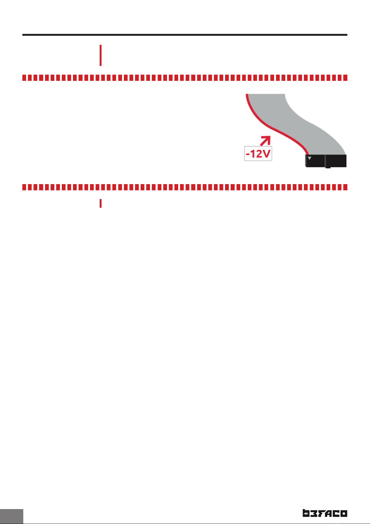
2- Pick your multimeter and select
DC Voltage mode (typically marked
as V=). Connect the black probe to
a Ground point (you can use the
sleeve of patch cable connected to any other module) and
place the red probe touching the point marked.
You should read a value
around 2.5V. Adjust care-
fully V-Ref trim-pot till
you see 2.500V exactly. If
you have a good multime-
ter (6000 counts or more)
that shows you 4 zeros,
you will be able to adjust this even more accurately.
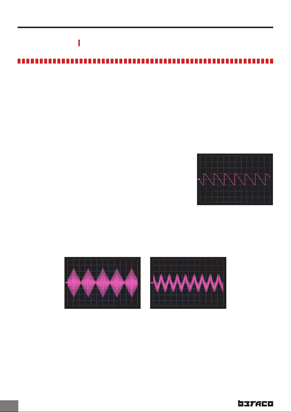
3- Place the Freq Pot in the middle position, the Octave
switch to the second position (C2) and the Timbre slider to
the minimum position. Select the Sine waveform and put
the Range switch on the Semitone Range position. Dou-
ble-check all the controls and if all is in its right spot, go
to the next step. During the next two steps, be sure to not
move Freq and Timbre controls. As those controls aect
the frequency, any move on them will aect your readings.
•
•
•
•
•
•
•
•
•
•
•
•
•
•
•
•
•
•
•
•
•
•
•
•
•
•
•
•
•
•
•
•
•
•
•
•
•
•
•
•
•
•
•
•
•
•
•
•
The module comes factory calibrated so this procedure is only necessary in exceptional cases. Please follow the steps
carefully. If you nd trouble during the calibration please drop us a mail at support@befaco.org and our technical team
will help you through the process.
To calibrate the VCO we will need a 0.5mm Flat Screwdriver, a Digital Multimeter (6000 counts or more would be ideal for
a very precise calibration but is not mandatory) and a Tuner. Any audio interface with a software tuner will do the job.
Before starting with the calibration process, power up the module and leave it warming up for 15 minutes. Once done,
we can start with the procedure.
PONY VCO

.8
SPECS AND CREDITS
USER MANUAL
Size: 4HP
Deeth: 30 mm
+12v: 32 mA
-12v: 25 mA
This module is the result of loads of hours of work, love, and care. We
would like to thank everybody that took the time to provide opinions,
warned about technical issues (Thanks Alex!!) and encouraged us to keep
going!! And of course THANK YOU! for the continuous support and trust in
Befaco! <3
Hardware, layout and documentation design by Befaco Team
Beta testing by José Ángel Cabrera, Miguel Eedl, and the Befaco team.
PONY VCO MISCELLANEA
Table of contents
Other Befaco Recording Equipment manuals

Befaco
Befaco ST AMP User manual

Befaco
Befaco STAmp 1U User manual

Befaco
Befaco MIDI THING User manual

Befaco
Befaco VCMC User manual

Befaco
Befaco BURST User manual

Befaco
Befaco HEX MIX VCA User manual

Befaco
Befaco Chopping Kinky V1 User manual

Befaco
Befaco STEREO STRIP User manual

Befaco
Befaco FXBOY V1 User manual

Befaco
Befaco TRS User manual
Popular Recording Equipment manuals by other brands

Advanced
Advanced Axis AV-V70-KIT installation instructions

Accuphase
Accuphase AD-50 instruction manual

Technics
Technics SH-8055 Service manual

Campbell
Campbell NL110 instruction manual

Tucker-Davis Technologies
Tucker-Davis Technologies UZ2 Hardware reference

Siemens
Siemens Trunk Interface II Series installation instructions