Befaco BURST User manual

B U R S T
U S E R M A N U A L

B U R S T P O W E R & I N T R O
P O W E R I N G T H E
M O D U L E
U S E R M A N U A L
T H A N S F O R P U R C H A S I N G A M O D U L E F R O M B E F A C O !
B E F O R E Y O U P LU G T H I S M O D U L E I N . . .
1.
Disconnect our cabinet from the mains.
2.
Triple check the power cord polarit .
The coloured line on the cable
(pin number one) is the -12V rail.
3. If you plug the module backwards you might burn it out and
unfortunately this is not covered by the warranty.
4. If you have any questions about this product please send them to:
befacosynth@gmail.com
I N T R O D U C T I O N D E S C R I P T I O N
Burst, is a trigger processor and generator, designed to add organic chain of events to
your modular setup. You can see it like
"Trigger Activated Trigger Burst".
Each time it is activated, either manually or with an external trigger, a given amount of
triggers are generated. You can control Time Division, Distribution, Quantity and
Probability of the bursts.
M O D U L E
R E F E R E N C E PA N E L O V E R V I E W
1.
Quantity Encode
Manual control of trigger amount
and Tap Tempo
2.
Led Round Display
Visual feedback of Trigger
Quantity, Burst and Pots settings.
3.
Ping Input
Sets the size of the time window
via trigger/clock.
4.
Quantity Knob // CV IN
CV input with attenuator for
Quantity.
5.
Dist ibution Knob // CV IN
Control how the triggers are
distributed inside the Burst.
6.
Time Div/Mult // CV IN
Divide or multiply the time
window.
.1
6.
Time Div/Mult // CV IN
Divide or multiply the time window.
7.
Manual T igge // T igg IN
Initialize the Burst manually or via
Gate/Trigger respectively.
8.
P obability Knob // CV IN
Add unpredictability to the "Trigger Train"
manually or by voltage respectively.
9.
Cycle Switch
Puts "Burst" in loop.
10.
EOC (End of Cycle Output)
Outputs a trigger each time burst finish
11.
Output
Main trigger Burst Out.
12.
Tempo Out
A clock at the internal tempo

B U R S T R E F E R E N C E
F U N C T I O N A L
M O D E S
U S E R M A N U A L
H O W I T W O R S ?
Burst will convert a trigger present in its input into a burst of triggers. Fitting in the time
given by a ping input and distributed according to the different parameters.
.2
PI N G I N G TH E U NI T
To keep things on time, Burst always works inside a
Time Window:
a time frame where
the burst generated will fit. It is similar to the concept of tempo but not necessary
repeating all the time. This concept might seem confusing, but you will get it easily!
As you can see on the schem below, the time window size is defined by the clock (tapping
the encoder or sending pulses to
Ping IN
) but not necessary follows it. Burst is not
clockable but
"Pinga le"
(thanks 4ms for the term). In both cases, frequency is set by
time between pulses but pingable devices don't need this pulses running all the time.
You can trig the burst at any time and will keep its size, so you can fit it quite easily to
your musical tempo.
Time Window /2
Initial
Time Window x2
With Burst synced to your tempo you can create all kind of
ratcheting effects and multiplications leading to doubles,
triplets, quintuplets and true Poly Rythms for your modular
system.
With very short time windows, Burst can help to synthesize
fast repeating transients for "hand clap like" sounds or
mordent drum hits.
Burst normal mode is one shot but it can also work in
repeating mode converting it in a handy clock dividir or
multiplier.
Working in Cycle Mode, is also an excellent master clock with
tap tempo functionality, and is able to achieve non linear
distributed clocks.

B U R S T R E F E R E N C E
U S E R M A N U A L
C O N T R O L S
QU AN TI TY EN CODER
The main control of Burst is the
Quantity Encoder
. It have two main functions.
.3
1 .
Control the amount of triggers that are included on the
urst
. The amount of triggers can be changed in any moment
but the changes will only be effective when a new burst start.
This setting is stored in non volatile memory, so its remains
even if the device is turned off. The maximum amount of trigers
is 32.
2.
Manual "Ping"/Tap Tempo.
Tapping it two times or more,
you can manually adjust the time window were the burst will
take place. If you tap it more than twice, the time between them
will be averaged to improve timing precision. This adjustments is
also store in non volatile memory.
LED ROU N D DI SPLAY
It gives you the next information:
1 .
Trigger Quantity
. Always one led keep light to show the
number of triggers inside the burst.
2.
Burst.
When a burst is started you can visualize it. Each
led represent a trigger on the burst and they blink in order to
show you the current state.
3.
Kno s/CV Settings:
When there is a change at manual
controls or CV INs the display will show this changes.
When various parameters are working at the same time, the visualization of the Burst
always prevail.
PI N G I N
Sets the size of the time window via trigger/clock. It have the same effect than tapping
the encoder. Once the time window is set, it remain set even if the clock stops. This
setting is not saved in non volatile memory.
F U N C T I O N A L
M O D E S
QU AN TI TY CV/AT TEN UATOR
With them you can control the amount of triggers via CV. Quantity CV value, is added or
subtracted to quantity encoder current value. Quantity pot attenuates the CV input so you
can adapt incoming CVs to your needs. This input is bipolar and accept voltages from -5v
to 1 0v in the next manner:
-5V
: Subtracts 16 triggers
0V
: Quantity remains
as set by the encoder.
5V:
Adds 1 6 triggers.
1 0V:
Adds 32 triggers.
Voltages over
1 0v or under
-5v are just
ignored.

B U R S T R E F E R E N C E
U S E R M A N U A L
.4
C O N T R O L S
F U N C T I O N A L
M O D E S
DI STRI BU TI ON N OB/C V I N
Controls how the triggers are distributed inside the burst. Distribution can be linear,
logarithmic or exponential, and can be controlled either manually or by voltage
respectively. That means, distance between triggers can be constant, or can change during
the burst (increase or decrease).
This parameter is useful for add "physics"
feeling to your trigger train, and make it
more dynamic and organic.
1 0v CV are accepted at the CV IN, and this
value is added to the pot value, allowing
negative voltages in the same amount the
pot is positive.
With the pot anticlockwise CV can go from
0 to 1 0V, with the pot at the middle CVs go
from -5v to 5v. With the pot clockwise -1 0v
to 0v will be accepted. Other voltages are
just ignored and don't represent any danger
for the module.
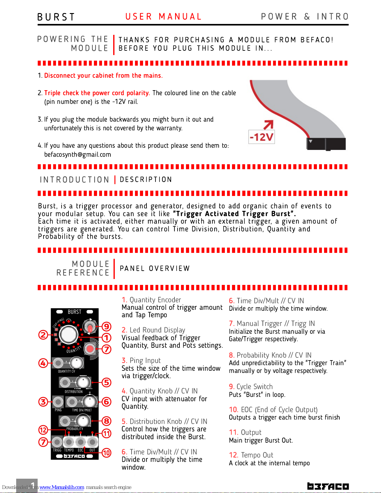
TI M E DI VI SI ON /M U LTI PLI C ATI O N N OB/CV I N
Sets This IN and its associate Manual control
knob, divide or multiply the time window by an
entire number.
nob and CV values are added together.
With the knob at center, and 0v at the CV IN it
doesn't have any effect. Clockwise is multiplied
by a maximum of eight, and counterclockwise is
divided by the same amount.
/2
x2
M AN UAL TRI GGER /TRI G GER I N
Sets Both initialize the burst, manually or via
trigger/gate respectively.
They work in "re-trigger" way so they always Initialize
the burst from the beggining. Trigg IN is dependent of
the probability adjustment but manual trigger isn't.
By default, the incoming trigger (either manual or via
Trigg IN) is always present on the out and is not
affected by Probability CV/ nob (the minimum trigger
on the out is always one).
But If you need the opposite behaviour, just push the
trigger button and hold it during three seconds. This
setting delete the initial trigger of the out and sets to
0 the minimum number of triggers on the burst. Same
operation will be used to get back to the default state.

B U R S T R E F E R E N C E
U S E R M A N U A L
.5
C O N T R O L S
F U N C T I O N A L
M O D E S
PRO BABI LI TY N O B/CV I N
With the Probability nob/CV you can add unpredictability to the "trigger train", manually
or by voltage respectively.
It controls how often the burst is randomly inhibited.
With 0v at the CV IN or the pot counterclockwise it remains untouched. With 1 0v or the
pot clockwise it never happen, and because of this, you can also use this parameter as an
"Inhibit" control.
Like on most INs, 1 0v CV are accepted, and this value is added to the pot value, allowing
negative voltages in the same amount the pot is positive.
With the pot anticlockwise CV can go from 0 to 1 0V, with the pot at the middle CVs go
from -5v to 5v. With the pot clockwise -1 0v to 0v will be accepted. Other voltages are just
ignored and don't represent any danger for the module.
C YCLE SWI TCH
Cycle switch puts Burst in loop mode so it repeats again and again after a trigger is
received. It have two positions:
UP
: Cycle ON, latch
DOWN
: Cycle OFF
In Cycle mode the triggers still affected by
Probability settings.
If a trigger is present the burst will be
reset from this point.
EO C OU T
A trigger each time burst finish. This is known as EOC (End of Cycle). Useful to chain any order
device so it triggers after burst finish.
TEM P O O U T
A clock at the internal tempo. Useful if you want to use Burst as main clock of your system.
S P E C S & C R E D I T S
M I S C E L L A N E A
* Size
: 8HP
* Depth
: 30mm
* +1 2v:
50mA
* -1 2v:
1 0mA
* Design
: Diego Rodríguez
* Firmware Coding
: Jeremy Bernstein & Eloi Flores
* Special thanks to
Jonatan Bernabeu, Pepe Coca,
Edu Tarradas "Clip", Pau Cabruja, Miguel Eedl and all
Befaco Team for their unpayable help during the
module development.
Table of contents
Other Befaco Recording Equipment manuals

Befaco
Befaco STEREO STRIP User manual

Befaco
Befaco AC/DC User manual

Befaco
Befaco FX BOY User manual

Befaco
Befaco VCMC 1.1 User manual

Befaco
Befaco VCMC User manual

Befaco
Befaco MIDI THING User manual

Befaco
Befaco AC/DC User manual

Befaco
Befaco VCMC User manual

Befaco
Befaco STAmp 1U User manual

Befaco
Befaco PONY VCO User manual