-7-
SECTION 3 : INSTALLATION INSTRUCTIONS
Within the installation and confirmation procedures are inspection/test steps which the installer must
perform to insure that the installation meets the manufacturer's specifications. These steps require the
installer to record the necessary information onto the "ASSEMBLER'S INSTALLATION SECTION
OF THE LIMITEDWARRANTYREPORT FORM" supplied, which MUST be returned to BELMONT
along with the warranty card.
[ 1 ] INSTALLATION REQUIREMENTS
Tools :
Standard tool kit including 1.5 mm, 2 mm, 3 mm and 5 mm allen keys.
Instruments :
Digital multimeter with an accuracy of 1%, capable of measuring 150 VAC and 10 mA DC,
and capable of indicating true RMS value within 1 sec.
Standard calculator.
Power Supply :
Prior to starting the installation, inspect the power supply and confirm that it is 120VAC ±10%,
and a 3 wire GROUNDED circuit, separately connected to the circuit breaker panel with an over
current protection device rated for 15A (Refer to Page 5, [2] ELECTRICAL REQUIREMENTS).
Record the voltage reading of power supply on "Assembler's Installation Report".
[ 2 ] UNPACKING
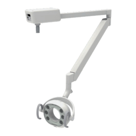
Unpack the entire contents of the shipping carton. Included within the shipping carton are :
Hardware Quantity
Head with Regular Cone ----------------------------------------------------------- 1
Main Controller---------------------------------------------------------------------- 1
Screw for chassis (M4 x 10 mm)-------------------------------------------------- 4
Screw for chassis (M4 x 20 mm)-------------------------------------------------- 1
Screw for nylon clamp on wall plate (M4 x 10 mm) --------------------------- 1
Stopper Ring ------------------------------------------------------------------------- 1
Nylon Clamp (3/8”)----------------------------------------------------------------- 1
Insulation Tube for interconnecting wires --------------------------------------- 1
Front cover seal---------------------------------------------------------------------- 4
Wall Plate----------------------------------------------------------------------------- 1
Lag Screws for wall plate (ø9 x 75 mm) ----------------------------------------- 4
Arm Mounting Bracket------------------------------------------------------------- 1
Machine Bolt (M8 x 20 mm) ------------------------------------------------------ 3
Washer (M8) ------------------------------------------------------------------------- 3
Sub Controller ----------------------------------------------------------------------- 1
Sub Controller Mounting wood screw (ø4.1 x 20 mm) ------------------------ 3
Head key------------------------------------------------------------------------------ 1
Arm collar ---------------------------------------------------------------------------- 1
Balance Arm ------------------------------------------------------------------------- 1
Balance Arm Wrench --------------------------------------------------------------- 1
Horizontal Arm W/2 x End Caps-------------------------------------------------- 1
Brake Screw (M6 x 6 mm)--------------------------------------------------------- 2
Brake Plug (Brass Plug ø5 X 4 mm) --------------------------------------------- 2
Retaining Bolt (M6 x 35 mm) ----------------------------------------------------- 2
Stopper Screw (M6 x 15 mm) ----------------------------------------------------- 1
Brake Spring (ø5 x 11 mm) -------------------------------------------------------- 1
Documentation Quantity
Installation manual ------------------------------------------------------------------ 1
Operators manual-------------------------------------------------------------------- 1
Limited Warranty / Report Form -------------------------------------------------- 1
Wall mounting Template ----------------------------------------------------------- 1
FDA Form 2579 --------------------------------------------------------------------- 1
Inspect contents of shipping carton for damage or missing components.
