Belmont buddy 2 User manual

buddy™2

BELMONT INSTRUMENT C ORPORATI ON
‘buddyTM2’Blood/Fluid Warmer
Operator’s Manual
Belmont Instrument Corp.
780 Boston Road
Billerica, MA 01821
EMERGO EUROPE
Molenstraat 15
2513 BH, The Hague
The Netherlands
Tel +31(0) 70 345 8570
Fax +31(0) 70 346 7299
CAUTION: Federal law (USA) restricts this device to sale by or on the order of a physician
702-00211/Rev B

Table of Contents
C H A P T E R 1 : S Y S T E M OV E R V I E W
Introduction…………………………………………………………………………………….. 1
Indications for Use and Contraindications……………………………………………………….. 1
System Overview………………………………………………………………………………… 2
System and Temperature Monitoring………………………………………………………….…. 3
Alarms and Alarm Messages……………………………………………………………………... 3
Control Panel: Display and Keys………………………………………………………………… 4
C H A P T E R 2 : O P E R A T I O N
Introduction…………………………………………………………………………………….. 5
Step-by-Step Summary of Operating Procedure………………………………………….……… 7
Mounting the Power Module Unit…………………………………………………………….… 7
Connecting the Heater Unit……………………………………………………………………... 8
Installing and Priming the Disposable Set………………………………………………..…..….. 8
Connect to Fluid Bag and Administration Set……………………………………………..…...... 9
Prime the Disposable Set……………………………………………..…..……………………... 9
Initiate Infusion………………………………………………………………………………… 10
Maintain Infusion………………………………………………………………………………. 10
End of Procedure……………………………………………..…..…………………………….. 11
Flow Characteristics………………………………………………………………………….…. 12
Operational Alarms and Troubleshooting………………………………………………….…… 13
C H A P T E R 3 : S E R V I C E A N D M A I N T E N A NC E
Introduction……………………………………………………………………………………. 17
Cleaning, Disinfection and Maintenance…………………………………………………..……. 18
System Operational Checkout…………………………………………………………..……..... 19
Periodic Maintenance…………………………………………………………………………... 20
Electromagnetic Compatibility………………………………………………………………...... 22
C H A P T E R 4 : T E C H N I C A L S P E C I F I C A T I O N S
Technical Specifications………………………………………………………………………… 23
C H A P T E R 5 : O R D E R I NG I NFO R M AT I O N
Ordering Information………………………………………………………………………….. 28

1
System Overview
I N T R OD U C T I O N:
The Belmont® buddy™2in-line Blood/Fluid Warmer combines advanced microprocessor
technology with an efficient heating system to provide a safe and simple system for low flow
fluid warming in a miniature package. The system warms blood or replacement IV fluid to
physiological temperature at flow rates up to 100 ml/min (6 L/hr) for crystalloids at 20 C and
up to 50 ml/min (3 L/hr) for packed red cells at 10 C. The heating unit is self-contained in a
hard shell case that is placed near the infusion site, minimizing IV line cool down and ensuring
that fluids are delivered normothermically. The IV pole-mounted power module, supplies
power to the Heater Unit, and displays the output temperature and alarm messages which alert
the user to abnormal conditions such as low flow, empty set, no heat, and over and under
temperature. The audible alarm may be muted, but visual indications of alarm states will always
be displayed.
I N D I CA T I O N S F OR U S E A N D C ON T R A I N DI C A T I O N S
The Belmont®buddy™2 Blood/Fluid Warmer is to be used to administer blood, blood
products and intravenous solutions. It is intended to be used by healthcare professionals in a
clinical environment to prevent hypothermia. The system is not meant for the infusion of
granulocyte suspensions.
Chapter
1

2
WARNING
The control system can only be used with the Belmont supplied disposable.
Do not alter the disposable, Heater Unit or Power Module.
Use only with crystalloid or anticoagulated blood product.
Not for infusion of drugs
Do not use in the presence of flammable anesthetic.
CAUTION
The system should not be used with pressure infusers. Blood and fluid bags contain
air. The set can vent large amounts of air from crystalloid, but with blood only small
amounts of air can be vented. The hand squeeze pumps, also known as a ball pump,
supplied with some blood sets, may be used to momentarily increase flow, but use
caution when doing so.
The system is an efficient blood and fluid warmer designed for flow rates below 100
ml/min. It is neither a resuscitation device nor a substitute for a rapid infusion system.
S Y S T E M O V E R V I EW
The buddy™2Blood/Fluid Warmer complete
system consists of the Power Module (with
AC/DC power supply), which is mounted on an
IV pole, the Heater Unit that is placed near the
patient at the infusion site, and the disposable set.
See Figure 1.
The Power Module incorporates the power supply,
display, alarm circuitry, and a magnet for storing the
Heater Unit when not in use (Show in Figure 1). The
bright alphanumeric display shows the output
temperature of the fluid and alerts the user to alarm
conditions.
The Heater Unit contains the heater plates and
temperature monitoring and control system.
Figure 1: The buddy™2 Complete System

3
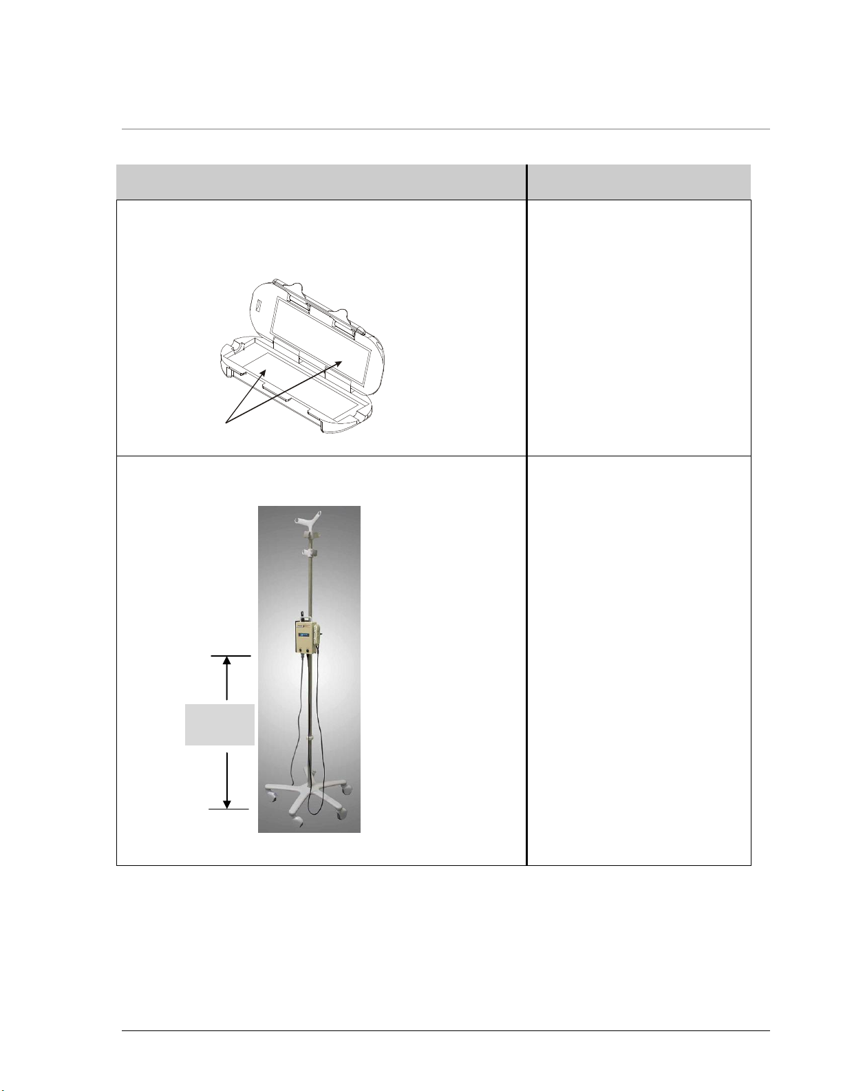
The disposable set has a sterile fluid path,
and is intended for single use only.
The disposable set has standard luer connectors
and can be connected to any standard catheter.
It contains two thin films, which contact the heater plates
for rapid heating of the fluid, and
two internal microporous membranes to
vent out-gassed air that is generated
during heating, see Figure 2. Figure 2: The buddyTM Disposable set
The set is color-coded and keyed to ensure proper placement in the Heater Unit, blue at the
input from a fluid administration set. Both heater plates are heated during operation. There is
a built in valve in the disposable set to prevent air entrainment into the patient and a pressure-
regulating valve at the input to protect the set and the patient from unintended exposure to
high pressure applied to the IV line. This valve will allow increase flow by application of
pressure, up to 300 mmHg, but will prevent pressure higher than this from reaching the set or
IV line distal to it. There is also a check valve at the output to prevent a back flow.
SYSTEM AND TEMPERATURE MONITORING
Blood or replacement fluid is heated as it passes through the disposable that is in contact with
the heater plates in the Heater Unit. Thermistors on the heater boards control and measure the
temperature of heater plates that in turn control the temperature of the infusate. The Power
Module displays the infusate temperature and alerts the user to alarm conditions. An over
temperature condition causes the unit to stop heating and issue an audible alarm. The low
temperature message (no audible alarm) informs the user that the flow rate is too rapid for the
device to maintain the temperature above 31 degrees Centigrade.
ALARMS AND ALARM MESSAGES:
Under any alarm condition, the system sounds an audible alarm, flashes a red LED, and
displays an alarm message on the screen. Certain alarms, such as Over Temperature, No
Heat/Check Connection, Over Current, Probe Fault and System Reset indicate system
problems and are always active.
The Empty Set/Check For Air alarm may be enabled or disabled from the front panel. If
this alarm is disabled, the message is still displayed, and the red LED is lit to alert the Operator.
BLUE
(INPUT)

4
C O N T RO L P A N E L : D I S P L A Y A N D K E Y S
The Power Module of the buddy™2Blood/Fluid Warmer is shown below:
POWER
The display is illuminated when the unit is plugged into the
AC outlet.
The ON/STANDBY key controls power from the Power
Module to the Heater Unit.
DISPLAY
The display unit shows the infusate temperature.
Under most alarm conditions the temperature display will be
replaced by the alarm message. An audible alarm is activated
whenever an alarm condition is detected. It can be silenced for 60 seconds by depressing the
ALARM MUTE key.
DISABLE/ENABLE EMPTY SET/CHECK FOR AIR ALARM
If the ALARM MUTE key is depressed and held for 3 seconds at any time after power up, the
Empty Set/Check For Air audible alarm will be disabled and the red LED will be illuminated.
If this alarm condition occurs while the audible alarm is disabled, the red LED will flash and the
alarm message will still display, but without the audible tone.
To enable the audible alarm after it has been disabled, depress and hold the ALARM MUTE key
for 3 seconds. The red LED lamp within will turn off.
Depressing ALARM MUTE key when the empty set condition occurs can also disable the
Empty Set/Check For Air audible alarm. Temperature is displayed on screen indicating that fluid
is being heated, the red LED is lit, and the alarm message is displayed.

5
Operation of the System
I N T R OD U C T I O N
This section reviews the set up and operation of the Belmont®buddy™2 Blood/Fluid Warmer
to ensure safe and effective operation of the system.
CAUTION:
Use of this device requires detailed familiarity with its operating procedures.
Read this manual thoroughly before operating this device.
Chapter
2

6
WARNINGS:
Use only the Belmont supplied disposable. The disposable set is a single-use,
sterile, non-pyrogenic fluid path.
Do not change or alter the disposable. Use extreme caution when handling the
disposable; do not expose the disposable to sharp objects.
Do not use in the presence of flammable anesthetics.
Do not open the Heater Unit during or after priming.
Do not open the Heater Unit during operation, as this could damage the
disposable.
Use only crystalloid to prime the unit. Do not use blood for the initial prime.
Do not attempt to prime unit or subject the disposable to flow outside of the
Heater Unit, as the disposable will be damaged.
The patient line must be completely free of air before fluid is administered.
Do not use for administration of drugs, cryo-precipitate, or granulocyte
suspensions.
Use only anticoagulated blood products.
Do not mix lactated Ringer’s or other solutions containing calcium with citrated
blood products.
Practice standard hospital policy when handling blood products. Treat blood as
if it were infected and clean up all spills immediately.
To avoid risk of electric shock, this device must only be connected to a supply
mains with protective earth.

7
S T E P - BY- S T E P S U M M A R Y O F O P E R A T I N G P R O C E D U R E S
Operating Steps
Detailed Information
Set-up
Make sure that you have all the
necessary supplies.
Inspect the Heater Unit to
ensure that the heater plates
are clean and dry. Wipe off
any particles or debris on
the plate with a soft cloth.
There are no adjustments
on the Heater Unit.
IV Pole Mounting
Mount the Power Module on the
IV Pole at 48” above the ground
for the operator to see and access.
Open the mounting screw on the
rear of the unit by turning it
counter clockwise until the IV
pole can be placed within the
holder.
Tighten the mounting screw by
turning it in a clockwise direction
until the unit is secured on the
pole.
Plug the Power Module to the
wall outlet.
Heater Plates
48” above
the ground

8
Operating Steps
Detailed Information
Connect Heater Unit to Power Module
Connect the Heater Unit to the
Power Module by aligning the dot
on receptacle to the pointed line
on the plug.
To disconnect, twist the plug
toward the arrow to release.
Install the Disposable Set
Carefully remove the
disposable from its pouch.
Install it into the Heater Unit,
being careful to line up the
orientation notches on the
disposable with the orientation
pins on the Heater Unit.
Take care not to damage the
disposable.
Align the dot
To the pointed line
BED
SHEET
CLAMP
Line up orientation hub on the
disposable with the notch in the
heater unit (RED to RED).
The heaterunit will not close if
they are not aligned.

9
Operating Steps
Detailed Information
BLUE
(INPUT)
The Heater Unit will not close if
the disposable is not installed
properly.
PATIENT
MALELUER
FEMALE
LUER
CONNECTTO
FLUID
Close and latch the case.
Connect to the Fluid Bag and Administration Set
Hang a fluid bag and
administration set.
Connect the fluid
administration set to the
disposable luer fitting with
the blue slide clamp.
Prime the Disposable Set
WARNING:
The case must remain closed during and after priming.
Open the roller clamps of the
administration set and prime the
unit making sure there is no air
visible in the IV line or patient
extension.
Tap the Heater Unit while
priming to expel any air bubbles
that may collect in the disposable.
Establish Power to the Heater Unit
Depress ON/STANDBY button
on the Power Module to supply
power to the Heater Unit.

10
Operating Steps
Detailed Information
Initiate Infusion
PATIENT
MALELUER
FEMALELUER
CONNECTTO
FLUID
BED
SHEET
CLAMP
Select an appropriate
catheter size for the
intended flow rate.
Using aseptic technique,
make patient connection
without entrapping air.
Adjust the roller clamp to
the desired flow rate.
Secure the Heater Unit
in a horizontal position,
on a flat surface near the
patient using bed sheet
clamp ensuring that there is
no strain on the patient line.
If a longer extension is
desired, it should be no
longer than 6 inches for
optimal thermal transfer.
Use of longer extensions
will result in some line
cooling from heater to
patient.
The preferred position is at
or below the level of the
insertion site.
Maintain Infusion
There are no adjustments on the Heater Unit.
You may see some condensation around the outer-edge of the
Heater Unit after running for an extended period of time. This
is normal and will not interfere with the system.
If withdrawing fluid from distal end of disposable set via a
syringe, do not exceed a rate of withdrawal of 100 ml/min.
Observe the power module
display to ensure the unit is
sensing flow and the flow is
within the normothermic
range, as indicated by the
infusate temperature reading
with no alarm message.
Respond to and correct
system alarms.

11
Operating Steps
Detailed Information
End of Procedure
Clamp roller clamp on the
administration set off.
Clamp the input end of
disposable set off using the
blue slide clamp.
Turn Heater Unit off by
pressing ON/STANDBY
button on the power
module. Unplug from the
wall outlet.
Open the heater unit and
remove disposable set.
Dispose of disposable set
using hospital practices for
bio-hazardous materials.

12
F L O W C H A RA C T E R I S T I C S
The Belmont®buddy™2 Blood/Fluid Warmer is designed for gravity flow. The maximum flow
rates achievable will be determined by the size of the catheter employed.
The disposable has been designed to withstand up to 300 mmHg infusion pressure, provided the
disposable set is within the Heater Unit and latched. The system is designed to maintain
normothermic temperature at flow rates specified (50 ml/min for undiluted RBC’s at 10ºC, and
100 ml/min for 20ºC crystalloid). However, at higher flows, the fluids administered may not heat
to normothermia. There are no adjustments for the Heater Unit.
Pressure Drop:
The disposable and heating unit does not restrict flow. If flow appears to be restricted:
Check the infusion site to ensure catheter has not infiltrated the surrounding tissue
Check to make sure line is not crimped or clamped off
Out gassed fluids may be causing air build up in the disposable. If air restriction is
suspected:
oDetach the unit from the patient connection
oHolding the case with the patient connection port upward, tap the case gently while
allowing a few seconds of free flow to remove air. Reattach the unit to the patient with a
fluid-to-fluid connection.
oIf flow continues to be restricted, replace the disposable set.
Air Venting
As fluid flows through the disposable set, it passes across microporous membranes, which can
vent air from the fluid. The air is then released through the side vents of the set. When infusing
crystalloid, the set can vent large amounts of air. With blood or blood products, the set
can vent only small amounts of air. CAUTION: When using blood or blood product, the
Operator should be vigilant to avoid infusing air especially if using a hand squeeze pump
during the infusion. If the set were to become filled with air, the system will activate the
EMPTY SET/CHECK FOR AIR alarm to alert the Operator to the problem. The fluid path of
the set is only about 7 ml, and therefore, only a few ml of air will trigger the alarm. In addition,
there is a pressure-regulating valve, incorporated into the disposable set, prevents potential air
entrainment into the system by stopping fluid flow if a partial vacuum condition is present.
During normal operation –water vapor, along with out-gassed air from warmed fluid, will be
vented and will cause condensation to appear within the side vents after prolonged use. This
should not be mistaken as a seal failure due to materials or workmanship.

13
O P E R A T I ON A L A L A R M S A N D T RO U B L E S H O OT I N G
The Belmont®buddy™2 Blood/Fluid Warmer detects and displays the following alarm
conditions:
Empty Set/Check for Air
Low Flow
Low Temperature
No Heat, Check Connection
Over Current
Over Temperature
Probe Fault
System Reset
The chart below details these alarms, the system response and the recommended user actions.
Alarm Message
Condition and System
Response
Probable Causes
Actions
Empty Set/Check for
Air
System detects an empty set
condition. Flash LED, display
message, and activate audible
alarm. Heater continues to
function normally.
Audible alarm may be
disabled in advance by
depressing ALARM MUTE
for 3 seconds or depressing
ALARM MUTE key when
condition occurs. Flashing
LED and message will occur
at alarm condition.
System automatically resets
and continues normal
operation when air is cleared
from the disposables.
1. Fluid source is
empty or air in the
fluid path.
2. Line is clamped.
1. If appropriate,
replace fluid supply.
2. Open clamps.
Low Flow
System automatically resets
and continues normal
operation when flow resumes.
Display message, no audible
alarm. Heating continues.
1. Fluid source is
empty.
2. Line is clamped
3. Flow is too low to
be detected.
4. Disposable has
clogged and is
restricting flow.
1. If appropriate,
replace fluid supply.
2. Open clamps.
3. Increase flow rate
until flow is
detected.
4. Replace disposable.

14
Alarm Message
Condition and System
Response
Probable Causes
Actions
Low Temperature
System detects fluid
temperature below 31C for
10 sec.
Display message, no audible
alarm. Heating continues.
Flow rate is set too fast.
Slow the flow rate using
roller clamp on the
administration set.
No Heat
Check Connection
System detects that
communication is lost
between the Heater Unit and
power module. Stop heating,
flash LED, alarm, and display
message.
If connection is restored,
system will resume normal
operation. If not, the system
turns power off and displays
‘Check Connection, Press
ON/STANDBY’ message.
1. Cable between the
Heater Unit and
Power Module is
disconnected or
loose.
2. Wire is broken.
1. Check and secure
connection between
power module and
Heater Unit. If this
fails to rectify the
problem obtain a
replacement Heater
Unit.
2. Replace unit.
**Over Current
System detects short circuit in
heater or heater cable. Stop
heating, flash LED, alarm,
and display message.
1. Heater circuit board
defective.
2. Wire is broken.
1. Unplug power
module from wall
outlet, and re-power.
2. Call service.
**Over Temperature
System detects fluid
temperature (i) Moderate to
High Flow: >42.5C for 2
min, or ≥ 48C for 2.5 sec,
or (ii) Low Flow: >42C for
2.5 sec or ≥ 44C for 1 sec,
or (iii) Output Plate
Temperature reaches 50.5C.
Stop heating, flash LED,
alarm, and display message.
1. Repeatedly stopping
and restarting during
high flow conditions.
2. Failure of the
microprocessor or
temperature sensor.
1. Clamp line, turn unit
off and unplug
power module from
wall outlet, and re-
power.
2. If failure reoccurs
obtain replacement
unit and contact
service.
**Probe Fault
Internal malfunction.
Hardware temperature
override circuit not
working properly.
Unplug power
module from wall
outlet, and re-power. If
not successful, call
service.

15
Alarm Message
Condition and System
Response
Probable Causes
Actions
**System Reset
Internal computer
malfunction. Alarm
continuously and display
message.
Loose watchdog
function on the Power
Module Processor.
Unplug power
module from wall
outlet, and re-power. If
not successful, call
service.
** At these four (4) alarms, system stops heating, flashes a red LED, alarms, and displays
message. Unplug Power Module from wall outlet, and re-plug into the wall outlet. Press
ON/STANDBY to apply power to the Heater Unit.

16
U S E R M A N A G E M E N T O F A L A R M S
1. To silence an audible alarm, depress the ALARM MUTE key. If the alarm condition
persists, the audible alarm will resume after 60 seconds, except the EMPTY
SET/CHECK FOR AIR alarm, which will remain disabled until air disappears and flow
resumes for at least 1 minute after which it can again be activated automatically.
2. The EMPTY SET/CHECK FOR AIR audible alarm may be disabled by depressing the
ALARM MUTE key for 3 seconds or depress ALARM MUTE key when this condition
occurs. The red LED will be lit steadily indicating that the alarm tone has been disabled.
If the Empty Set condition occurs during this time, the LED will flash and message will
appear on the screen.
To re-enable the alarm tone, depress and hold ALARM MUTE key for 3 seconds, the red
LED will no longer lit indicating that normal operation with alarm tone enabled have
been restored.
3. The LOW TEMPERATURE message is not an alarm condition and does not produce
an alarm tone. It usually indicates that the flow rate is set too fast; reduce the flow to get
rid of the message.
4. To reset the NO HEAT/CHECK CONNECTION alarm after the system turns the
power off, press ON/STANDBY button on the Power Module to turn the heater ON to
resume operation.
5. The following alarms indicate a probable system fault: OVER CURRENT, OVER
TEMPERATURE, PROBE FAULT, and SYSTEM RESET.
To reset or retry, remove Power Module from the wall outlet then re-connect to the wall
outlet. Press ON/STANDBY key to turn the heater on to resume operation.

17
Service and Maintenance
I N T R OD U C T I O N
The Belmont®buddy™2Blood/Fluid Warmer has no user serviceable parts, and does not require
calibration. Routine maintenance consists of cleaning and inspecting the Heater Unit after each
use and testing the system operational and routinely test for leakage current to ensure against
electrical shock hazard. The circuit diagram, component part lists, descriptions, and calibration
instructions will be provided to assist service personnel in device repair.
Chapter
3
WARNING:
Test leakage current periodically to insure against electrical shock
hazard
CAUTION
Do not open the Power Module. There are no serviceable parts inside the
housing. Opening the system will void the warranty.
CAUTION
The heater plates in the heater unit are sealed. Inspect the seals to insure their
integrity after each use. If the seal is not intact, do not use. Do not try to open
or to service the heater unit.
CAUTION
Check the integrity of the wires between the heater unit and power module. If
there is evidence of fraying or damage do not use and return the unit for
service.
Table of contents
Other Belmont Medical Equipment manuals

Belmont
Belmont Allon User manual

Belmont
Belmont Bel-Cypher N User manual

Belmont
Belmont 900 Series User manual

Belmont
Belmont X-Calibur V BEL-50N User manual

Belmont
Belmont Bel-Nova AL-D101G User manual

Belmont
Belmont Criticool 6.3 Quick start guide

Belmont
Belmont CritiCool MINI User manual

Belmont
Belmont PHOT-X IIs 505 User manual

Belmont
Belmont RI-2 User manual

Belmont
Belmont CliniLogger User manual