926000518
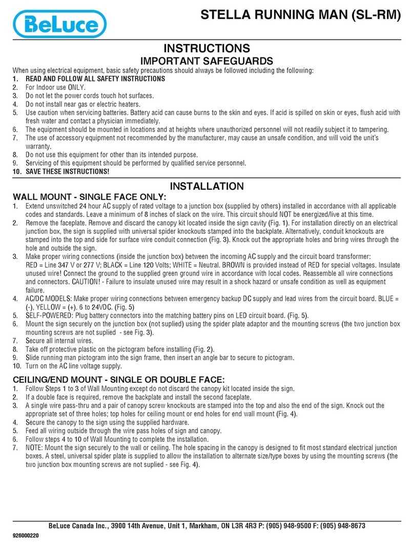
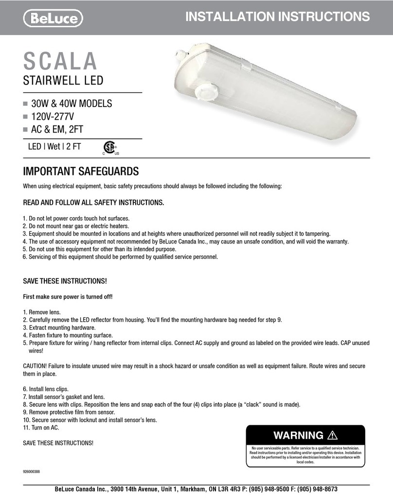
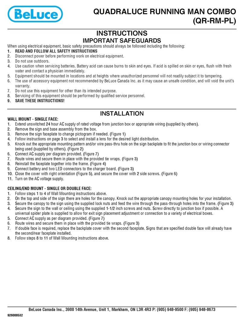
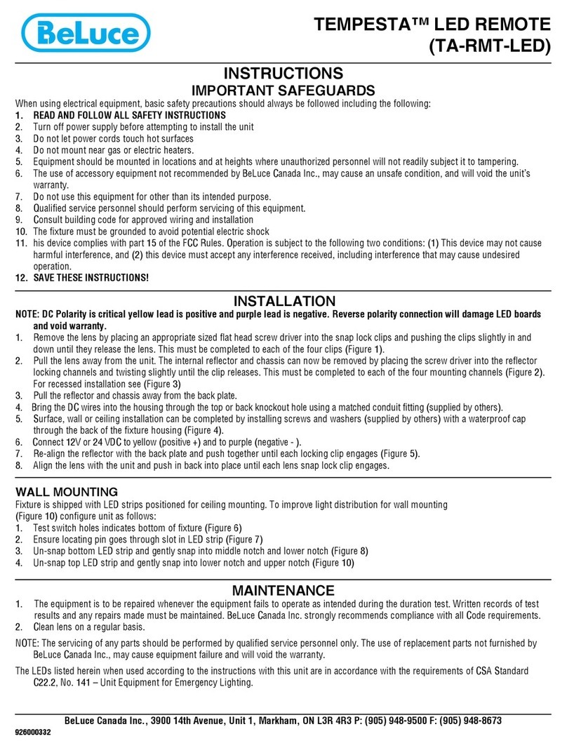
1
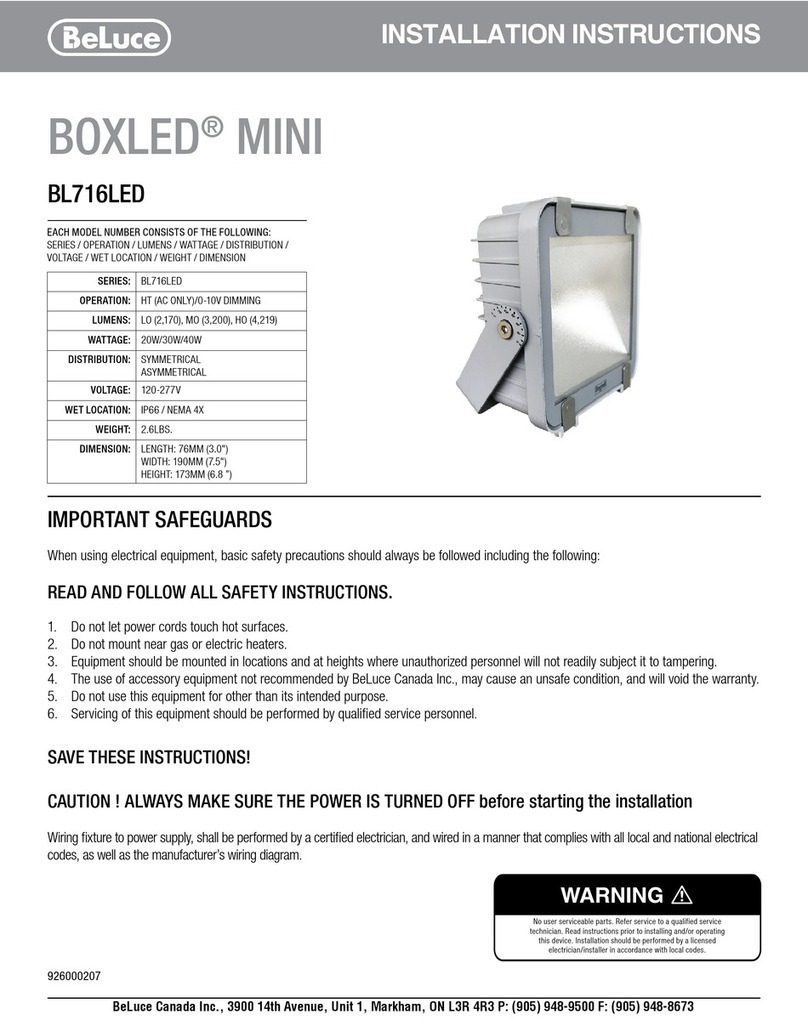
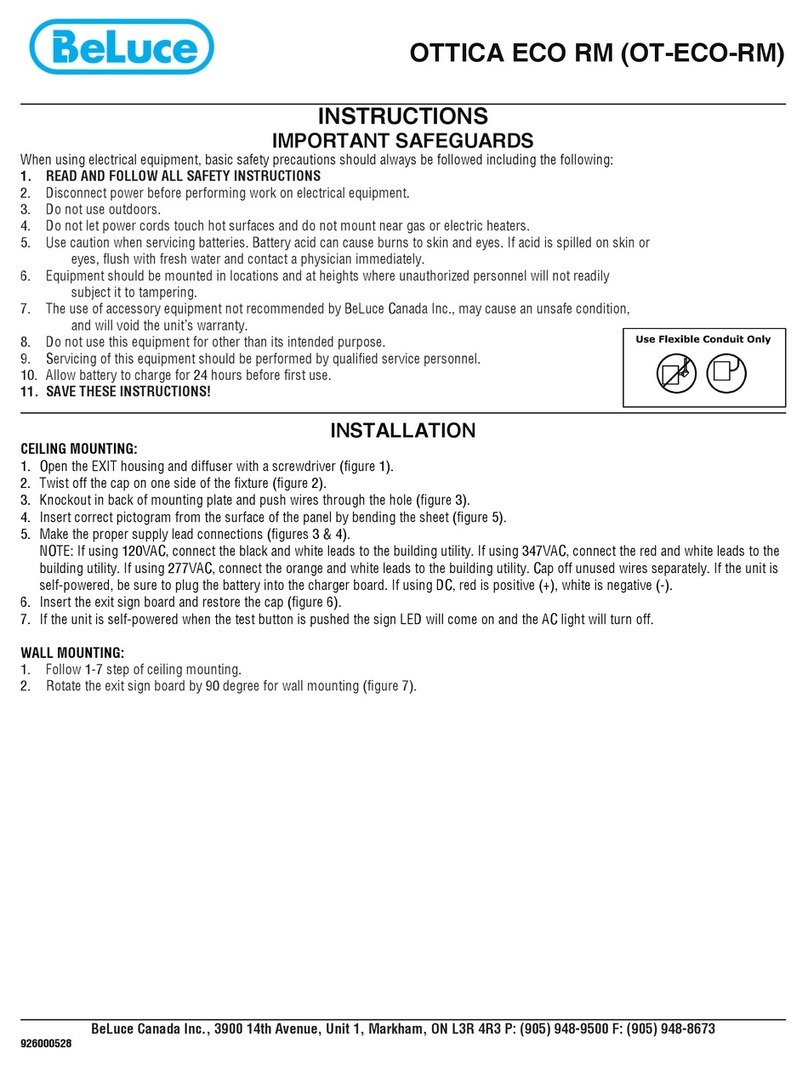
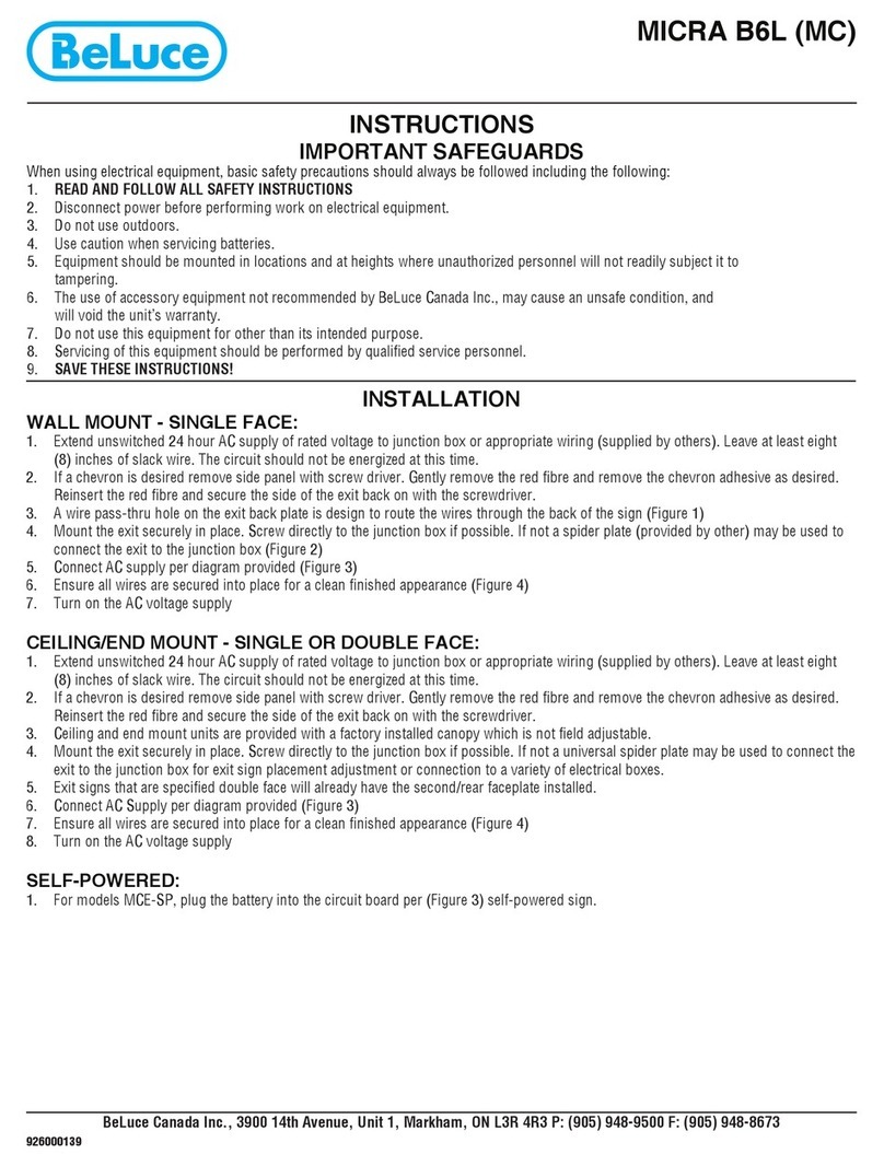
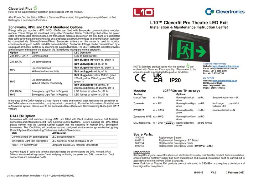
Box assembly
2
Back box
3
Trim plate
5
Pictograms
6
White insert
7
Angle bars (x4)
8
Bracket
9
Mounting bracket (x2)
10
Wedge
11
Canopy
12
¾" Bushing
13
6-32¾" Pan head screw (x2)
14
6-32½" Pan head screw (x2)
17
6-32 K-lock nut (x4)
16
6 " Pan head st screw (x2)
15
6-32¼" Flat head screw (x2)
18
4
Lens
19
Spider plate
20
Spider plate screw kit
21
8-32 K-lock nuts (x4)
22
#8 washer (x4)8-32 " Pan head screw (x4)
Components
1
1
2
2
A A
B B
COMMON STEPS SURFACE CEILING MOUNT
1
1
2
2
A A
B B
COMMON STEPS SURFACE CEILING MOUNT
Cover
Box assembly
Common Mounting Steps:
INSTALLATION
1. Remove cover from box assembly by removing screw on end
of box assembly.
6. For self-powered sign, plug battery into LED board.
7. Select pictogram. Install white insert or pictogram .
2. Knock out appropriate holes for mounting and install ¾" bushing
in entry hole and feed wires through.
3. For t-bar, pendant, or ceiling recessed, knock out top holes.
4. For ceiling, knock out top, for surface end, knock out end, for
surface wall, knock out side.
1
1
2
2
A A
B B
COMMON STEPS SURFACE CEILING MOUNT
Protective sleeve
A
1
1
2
2
A A
B B
COMMON STEPS SURFACE CEILING MOUNT
UNDERNEATH FIBER
INSERT FLAT HEAD SCREWDRIVER
TO POP UP BUTTON CAREFULLY
Underneath pictogram, insert
flat head screwdriver to pop up
button carefully
DETAIL A
SCALE .24:1
5. Remove protective sleeve from LED strip.
1
Box assembly
2
Back box
3
Trim plate
5
Pictograms
6
White insert
7
Angle bars (x4)
8
Bracket
9
Mounting bracket (x2)
10
Wedge
11
Canopy
12
¾" Bushing
13
6-32¾" Pan head screw (x2)
14
6-32½" Pan head screw (x2)
17
6-32 K-lock nut (x4)
16
6 " Pan head st screw (x2)
15
6-32¼" Flat head screw (x2)
18
4
Lens
19
Spider plate
20
Spider plate screw kit
21
8-32 K-lock nuts (x4)
22
#8 washer (x4)8-32 " Pan head screw (x4)
1
Box assembly
2
Back box
3
Trim plate
5
Pictograms
6
White insert
7
Angle bars (x4)
8
Bracket
9
Mounting bracket (x2)
10
Wedge
11
Canopy
12
¾" Bushing
13
6-32¾" Pan head screw (x2)
14
6-32½" Pan head screw (x2)
17
6-32 K-lock nut (x4)
16
6 " Pan head st screw (x2)
15
6-32¼" Flat head screw (x2)
18
19
Spider plate
20
Spider plate screw kit
21
8-32 K-lock nuts (x4)
22
#8 washer (x4)8-32 " Pan head screw (x4)
BeLuce Canada Inc., 3900 14th Avenue, Unit 1, Markham, ON L3R 4R3 P: (905) 948-9500 F: (905) 948-8673


