IMPORTANT SAFEGUARDS
When using electrical equipment, basic safety precautions should always be followed including the following:
1. READ AND FOLLOW ALL SAFETY INSTRUCTIONS
2. For Indoor use ONLY.
3. Do not let the power cords touch hot surfaces.
4. Do not install near gas or electric heaters.
5. Use caution when servicing batteries. Battery acid can cause burns to the skin and eyes. If acid is spilled on skin or eyes, flush acid with
fresh water and contact a physician immediately.
6. The equipment should be mounted in locations and at heights where unauthorized personnel will not readily subject it to tampering.
7. The use of accessory equipment not recommended by the manufacturer, may cause an unsafe condition, and will void the unit’s
warranty.
8. Do not use this equipment for other than its intended purpose.
9. Servicing of this equipment should be performed by qualified service personnel.
10. SAVE THESE INSTRUCTIONS!
INSTALLATION
WALL MOUNT - SINGLE FACE ONLY:
1. Extend unswitched 24 hour AC supply of rated voltage to a junction box (supplied by others) installed in accordance with all applicable
codes and standards. Leave a minimum of 8 inches of slack on the wire. This circuit should NOT be energized/live at this time.
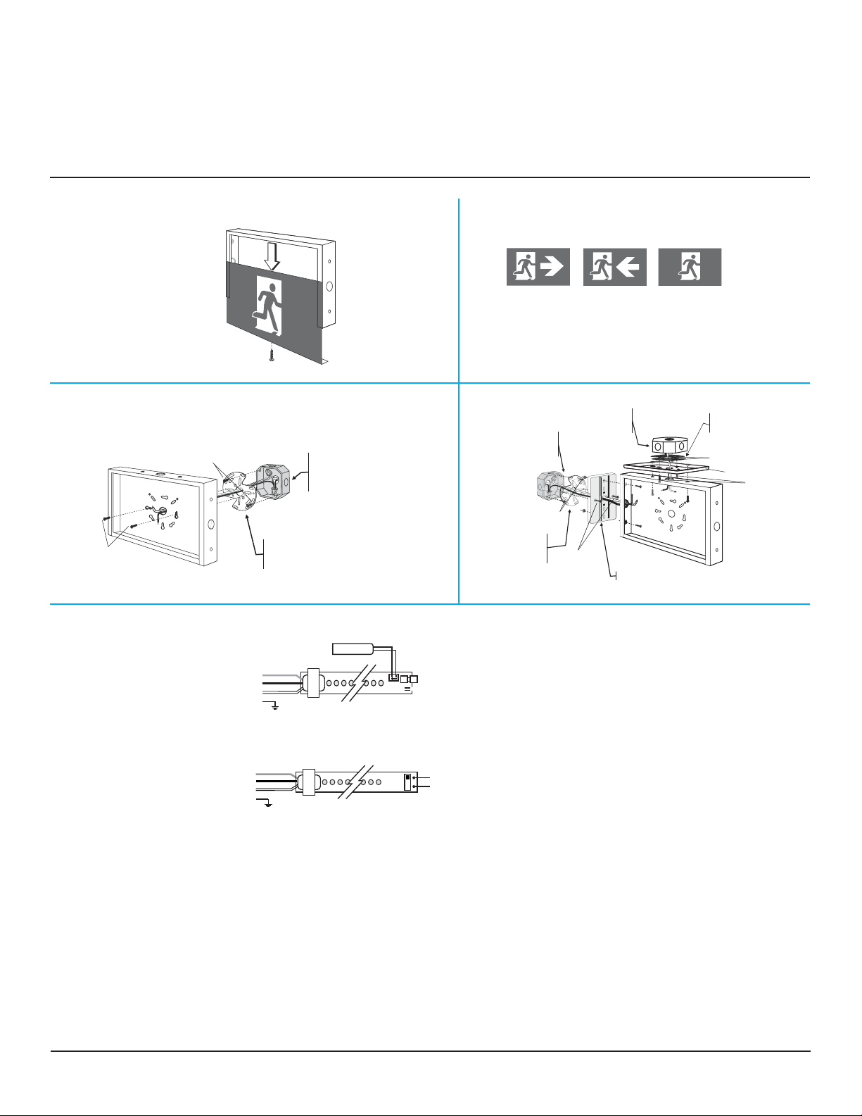
2. Remove the faceplate. Remove and discard the canopy kit located inside the sign cavity (Fig. 1). For installation directly on an electrical
junction box, the sign is supplied with universal spider knockouts stamped into the backplate. Alternatively, conduit knockouts are
stamped into the top and side for surface wire conduit connection (Fig. 3). Knock out the appropriate holes and bring wires through the
hole and outside the sign.
3. Make proper wiring connections (inside the junction box) between the incoming AC supply and the circuit board transformer:
RED = Line 347 V or 277 V; BLACK = Line 120 Volts; WHITE = Neutral. BROWN is provided instead of RED for special voltages. Insulate
unused wire! Connect the ground to the supplied green ground wire in accordance with local codes. Reassemble all wire connections
and connectors. CAUTION! - Failure to insulate unused wire may result in a shock hazard or unsafe condition as well as equipment
failure.
4. AC/DC MODELS: Make proper wiring connections between emergency backup DC supply and lead wires from the circuit board. BLUE =
(-), YELLOW = (+). 6 to 24VDC. (Fig. 5)
5. SELF-POWERED: Plug battery connectors into the matching battery pins on LED circuit board. (Fig. 5).
6. Mount the sign securely on the junction box (not suplied) using the spider plate adaptor and the mounting screws (the two junction box
mounting screws are not suplied - see Fig. 3).
7. Secure all internal wires.
8. Take off protective plastic on the pictogram before installing (Fig. 2).
9. Slide running man pictogram into the sign frame, then insert an angle bar to secure to pictogram.
10. Turn on the AC line voltage supply.
STELLA RUNNING MAN (SL-RM)
INSTRUCTIONS
926000220
CEILING/END MOUNT - SINGLE OR DOUBLE FACE:
1. Follow Steps 1 to 3 of Wall Mounting except do not discard the canopy kit located inside the sign.
2. If a double face is required, remove the backplate and install the second faceplate.
3. A single wire pass-thru and a pair of canopy screw knockouts are stamped into the top and also the end of the sign. Knock out the
appropriate set of three holes; top holes for ceiling mount or end holes for end wall mount (Fig. 4).
4. Secure the canopy to the sign using the supplied hardware.
5. Feed all wiring outside through the wire pass holes of sign and canopy.
6. Follow steps 4 to 10 of Wall Mounting to complete the installation.
7. NOTE: Mount the sign securely to the wall or ceiling. The hole spacing in the canopy is designed to fit most standard electrical junction
boxes. A steel, universal spider plate is supplied to allow the installation to alternate size/type boxes by using the mounting screws (the
two junction box mounting screws are not suplied - see Fig. 4).
BeLuce Canada Inc., 3900 14th Avenue, Unit 1, Markham, ON L3R 4R3 P: (905) 948-9500 F: (905) 948-8673