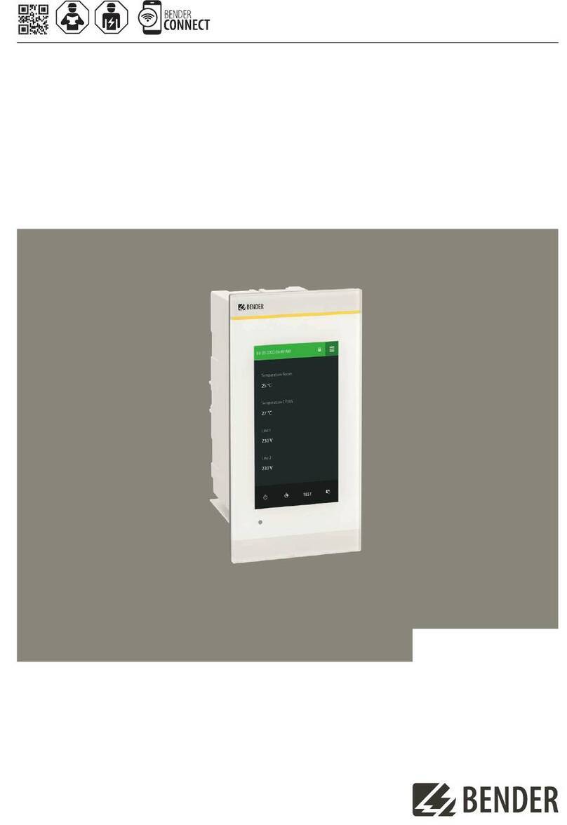
Bender COMTRAXX CP9 Series User manual

Manual ENCP9xx-x_D00406_00_M_XXEN/04.2020
COMTRAXX® CP9xx-x – Control Panel
Customised alarm indicator and operator panel for medical locations
and other areas

2 CP9xx-x_D00406_00_M_XXEN/04.2020
Service and support for Bender products
First-level support
Technical support
Carl-Benz-Strasse 8 • 35305 Grünberg • Germany
Telephone: +49 6401 807-760
0700BenderHelp *
Fax: +49 6401 807-629
E-mail: support@bender-service.de
Available on 365 days from 7.00 a.m. to 8.00 p.m. (MEZ/UTC +1)
* Landline German Telekom: Mon-Fri from 9.00 a.m. to 6 p.m.: 6.3 cents/30 sec.;
remaining time: 6.3 cents/min.
Mobile phone: higher, depending on mobile phone tariff
Repair service
Repair, calibration and replacement service
Londorfer Strasse 65 • 35305 Grünberg • Germany
Telephone: +49 6401 807-780 (technical issues) or
+49 6401 807-784, -785 (commercial issues)
Fax: +49 6401 807-789
E-mail: [email protected]
Field service
On-site service
Telephone: +49 6401 807-752, -762 (technical issues) or
+49 6401 807-753 (commercial issues)
Fax: +49 6401 807-759
E-mail: fieldservice@bender-service.de
Mon-Thu 7.00 a.m. to 4.00 p.m., Fri 7.00 a.m. to 1 p.m. (MEZ/UTC +1)

CP9xx-x_D00406_00_M_XXEN/04.2020 3
COMTRAXX® CP9xx-x – Control Panel
Table of Contents
1 General instructions .........................................................................5
1.1 How to use this manual..............................................................................................5
1.2 Indication of important instructions and information ...................................5
1.2.1 Signs and symbols ........................................................................................................5
1.3 Training courses and seminars.................................................................................5
1.4 Delivery conditions.......................................................................................................5
1.5 Inspection, transport and storage ..........................................................................6
1.6 Warranty and liability...................................................................................................6
1.7 Disposal of Bender devices........................................................................................6
1.8 Safety .................................................................................................................................7
2 Product description ...........................................................................9
2.1 Intended use...................................................................................................................9
2.2 Device features ........................................................................................................... 10
2.3 Applications .................................................................................................................17
2.4 Function......................................................................................................................... 17
2.5 Software products used........................................................................................... 18
2.6 BMS page of the CP9xx-x alarm indicator and operator panel.................18
2.7 Address configuration and termination............................................................ 18
3 Mounting and connection............................................................. 19
3.1 Mechanical installation ............................................................................................ 19
3.1.1 General description................................................................................................... 19
3.1.2 Opening and closing the front plate ..................................................................20
3.1.3 Removing the front plate of CP915 and CP924..............................................22
3.2 Mounting instructions.............................................................................................. 23
3.2.1 Mounting a flush-mounting enclosure with bezel frame enclosure ...... 24
3.2.2 Cross section view flush-mounting enclosure with bezel frame .............25
3.2.3 Cross section view flush-mounting enclosure with bezel frame for
cavity wall mounting ................................................................................................ 26
3.3 Fastening, cable entry .............................................................................................. 27
3.3.1 Fastening....................................................................................................................... 27
3.3.2 Cable entry ................................................................................................................... 27
3.4 Electrical connection................................................................................................. 29
4 Important information................................................................... 31
5 Technical data.................................................................................. 33

4 CP9xx-x_D00406_00_M_XXEN/04.2020

CP9xx-x_D00406_00_M_XXEN/04.2020 5
COMTRAXX® CP9xx-x – Control Panel
1 General instructions
1.1 How to use this manual
This manual is intended for qualified personnel working in electrical engineering and
electronics!
Part of the device documentation, in addition to this manual, is the enclosed
"Safety instructions for Bender products".
Read the manual before mounting, connecting and commissioning the device.
Always keep the manual within easy reach for future reference.
1.2 Indication of important instructions and information
I Danger!Indicates a high risk of danger that will result in death or serious injury if not
avoided.
I Warning! Indicates a medium risk of danger that can lead to death or serious injury if not
avoided.
I Caution!Indicates a low-level risk that can result in minor or moderate injury or damage to
property if not avoided.
i
Information can help to optimise the use of the product.
1.2.1 Signs and symbols
Disposal Temperature range Protect from dust
Protect from mois-
ture
Recycling RoHS directives
1.3 Training courses and seminars
www.bender.de -> Know-how -> Seminars.
1.4 Delivery conditions
The conditions of sale and delivery set out by Bender apply. These can be obtained from Bender
in printed or electronic format.
The following applies to software products:
“Software clause in respect of the licensing of standard software as part of de-
liveries, modifications and changes to general delivery conditions for products
and services in the electrical industry.”
Die Elektroindustrie

6 CP9xx-x_D00406_00_M_XXEN/04.2020
General instructions
1.5 Inspection, transport and storage
Check the shipping and device packaging for transport damage and scope of delivery. The follow-
ing must be observed when storing the devices:
1.6 Warranty and liability
Warranty and liability claims in the event of injury to persons or damage to property are excluded
in case of:
• Improper use of the device.
• Incorrect mounting, commissioning, operation and maintenance of the device.
• Failure to observe the instructions in this operating manual regarding transport, com-
missioning, operation and maintenance of the device.
• Unauthorised changes to the device made by parties other than the manufacturer.
• Non-observance of technical data.
• Repairs carried out incorrectly.
• Use of accessories and spare parts not recommended by Bender.
• Catastrophes caused by external influences and force majeure.
• Mounting and installation with device combinations not recommended by the manufac-
turer.
This operating manual and the enclosed safety instructions must be observed by all persons
working with the device. Furthermore, the rules and regulations that apply for accident preven-
tion at the place of use must be observed.
1.7 Disposal of Bender devices
Abide by the national regulations and laws governing the disposal of this device.
For more information on the disposal of Bender devices, refer to
www.bender.de -> Service & support.

CP9xx-x_D00406_00_M_XXEN/04.2020 7
COMTRAXX® CP9xx-x – Control Panel
1.8 Safety
If the device is used outside the Federal Republic of Germany, the applicable local standards and
regulations must be complied with. In Europe, the European standard EN 50110 applies.
I Danger!Risk of fatal injury due to electric shock! Touching live parts of the system carries the
risk of:
• A fatal electric shock
• Damage to the electrical installation
• Destruction of the device
Before installing and connecting the device, make sure that the installation has been de-ener-
gised. Observe the rules for working on electrical installations.

8 CP9xx-x_D00406_00_M_XXEN/04.2020
Product description

CP9xx-x_D00406_00_M_XXEN/04.2020 9
COMTRAXX® CP9xx-x – Control Panel
2 Product description
2.1 Intended use
The CP9xx-x alarm indicator and operator panels are intended for use in medical facilities as well
as industrial and single-purpose buildings.
They are used for:
• Display and visualisation of operating, warning and alarm messages
• Central control and parameter setting of BMS bus devices (BMS = Bender Measuring
Device Interface)
• Output of visual and acoustic warning messages
• Indication of measured values and setting of limit values for the purpose of measured
value monitoring of BMS-capable Bender monitoring systems, such as MEDICS®, RCMS
or EDS.
In addition, they are used for display, control and operation of:
• Operating theatre tables
• Supply systems for medical gases
• Air conditioning and ventilation systems
• Room lighting
• Communication systems
• Third-party systems
All technical devices installed in one alarm indicator and operator panel constitute a technical
centre in the respective room. Please heed the limits of the area of application indicated in the
technical specifications. Any other use than that described in this manual is regarded as improper.
Intended use implies:
• System-specific settings
• Observation of all information in the operating manual
• Compliance with test intervals

10 CP9xx-x_D00406_00_M_XXEN/04.2020
Product description
2.2 Device features
The CP9xx-x series includes the following variants of customised alarm indicator and operator
panels:
• CP9xx-F (only with front foil)
• CP9xx-G (only with glass front plate)
• CP9xx-H (with front foil and glass front plate)
The following basic types are described in the CP9xx-x series:
CP907-F, CP915-F, CP924-F with
front foil Control Panel with
COMTRAXX®
CP9xx-F alarm indicator and operator panels are equipped
with a front foil behind which the various
touch monitors are installed.
CP907-F Alarm indicator and operator panel with complete CP907
(B95061080) integrated behind a foil (installation with
inspection window and retaining frame).
CP915-F Alarm indicator and operator panel with PCAP touch mon-
itor (15.6", 16:9 format).
CP921-F Alarm indicator and operator panel with resistive touch
monitor (21.5", 16:9 format).
CP924-F Alarm indicator and operator panel with resistive touch
monitor (24", 16:9 format). For the 24" version, the highly
transparent foil is used.
CP915-G and CP924-G with glass
front plate in bezel frame or
mounting frame
The CP915-G and CP924-G alarm indicator and operator
panels cannot be equipped with any further components
or accessories.
CP9xx-H Alarm indicator and operator panels with glass front plate
and foil front (15.6", 24", 16:9 format)
i
Since with the matt, antibacterial front foil the display surfaces of the monitors and also in-
spection windows of other components must be coated for better transparency, the use of the
highly transparent foil is preferred.
i
Foil touch panels are individually programmed and are usually connected to a remote or exter-
nal I/O control unit, which in turn is set up and parameterised individually according to the
project. Depending on the requirements, the CP9xx-x alarm indicator and operator panel can
be provided with one or two front plates. The front plates are usually hinged on the right or left
and right side.
i
The individual and project-related elevation illustrations, circuit diagrams, programming and
datasheets are also an important part of this manual. These must also be read and observed
prior to commissioning and operation.

CP9xx-x_D00406_00_M_XXEN/04.2020 11
COMTRAXX® CP9xx-x – Control Panel
Some implementation examples are given below:
Fig. 2–1 CP915-F in bezel frame enclosure with individual, project-specific internal components

12 CP9xx-x_D00406_00_M_XXEN/04.2020
Product description
Fig. 2–2 CP921-F in bezel frame enclosure with individual, project-specific internal components

CP9xx-x_D00406_00_M_XXEN/04.2020 13
COMTRAXX® CP9xx-x – Control Panel
Fig. 2–3 CP921-F with two front plates in bezel frame enclosure.
Lower front plate with individual, project-specific internal components

14 CP9xx-x_D00406_00_M_XXEN/04.2020
Product description
Fig. 2–4 CP924-F with two front plates in bezel frame enclosure.
Right front plate with individual, project-specific internal components
Fig. 2–5 CP915-F with mounting frame with individual, project-specific internal components

CP9xx-x_D00406_00_M_XXEN/04.2020 15
COMTRAXX® CP9xx-x – Control Panel
Fig. 2–6 CP924-F with two front plates in bezel frame enclosure (including examples of customised indi-
vidual internal components)
Fig. 2–7 CP924-H with two front plates in bezel frame enclosure, upper front plate glass, lower front plate
with foil front (including examples of customised individual internal components)

16 CP9xx-x_D00406_00_M_XXEN/04.2020
Product description
Fig. 2–8 CP924-F with two front plates in bezel frame enclosure (irongrey, including examples of custom-
ised individual internal components)
Fig. 2–9 CP924-H with two front plates in bezel frame enclosure
Left front plate glass, right front plate foil front and individual, project-specific internal components

CP9xx-x_D00406_00_M_XXEN/04.2020 17
COMTRAXX® CP9xx-x – Control Panel
Fig. 2–10 CP924-H with two front plates with bezel frame enclosure
Upper front plate glass, lower front plate with foil front and individual, project-specific internal compo-
nents
2.3 Applications
• Optimum visualisation on the display tailored to the user
• Integration of compatible Bender products (ISOMETER®, ATICS®, RCMS, EDS, LINETRAXX®
and MEDICS® systems, universal measuring devices and energy meters)
• Individual instructions in case of alarms (optionally available)
• Selective notification to different users in case of alarms
• Control and regulation of systems such as air conditioning or blinds control.
2.4 Function
CP9xx-x alarm indicator and operator panels can be integrated into the existing EDP structure like
PCs, if required. Contact your IT administrators in this regard. After connection to the network and
compatible Bender products, all system devices can be accessed from any PC via a web browser.
In this way, all important system information is directly available.
Verified web browsers: Microsoft Internet Explorer, Mozilla Firefox, Google Chrome
Each alarm indicator an operator panel is individually configured and tailored to the requirements
of the user.

18 CP9xx-x_D00406_00_M_XXEN/04.2020
Product description
2.5 Software products used
CP9xx-x alarm indicator and operator panels are equipped with the COMTRAXX® user interface. It
is described separately in the "COMTRAXX®" manual.
2.6 BMS page of the CP9xx-x alarm indicator and operator panel
The majority of Bender devices communicate via the internal BMS bus.
The CP9xx-x alarm indicator and operator panel can be operated as a master or as a slave.
i
The CP9xx-x alarm indicator and operator panel is to be operated as master when:
- Parameters are queried or changed
- Specific control commands are given
Please note that not all BMS masters can surrender their master function!
2.7 Address configuration and termination
To ensure proper functioning of the CP9xx-x alarm indicator and operator panel, correct address
assignment and termination is of utmost importance.
i
On delivery, the systems are pre-programmed according to the project agreements and the ad-
dressing is correct.
i
Multiple assignment of addresses
The default system name on all Bender BCOM devices is "SYSTEM". If several systems with the
same system name are integrated into the same network, addresses are assigned twice. This
leads to transmission errors. Always enter a unique BCOM system name during initial setup.
i
On delivery, all project-specific settings are available.

CP9xx-x_D00406_00_M_XXEN/04.2020 19
COMTRAXX® CP9xx-x – Control Panel
3 Mounting and connection
3.1 Mechanical installation
3.1.1 General description
The mechanical design of the enclosure for flush mounting with bezel frame is oriented toward
longevity and particularly suited for the high hygienic requirements in medical locations. The en-
closures are all custom made to suite the technical and mechanical requirements on site.
The actual flush-mounting enclosure is made of stiff, grey 4 mm PVC plastic or 3 mm aluminium
with an extruded aluminium profile of natural aluminium colour.
The bezel frame covers a gap of up to 13 mm. Please refer to the chapter „3.2.1 Mounting a
flush-mounting enclosure with bezel frame enclosure“ for more information
The size of the circular gap between the bezel frame and the front plate is 0.5 mm.
The front plate features a concealed seal to offer the highest possible level of protection.
The front plate is attached to the bezel frame with concealed hinges. The location of the hinges
are according to the individual elevation illustrations.
CP9xx-G alarm indicator and operator panels have a glass front plate without hinges. The glass
front plate is retained in the enclosure by a snap-in mechanism.
I Caution!Damage to the glass front plate!
Placing the suction lifter in the middle and pulling only at this point may damage the glass
front plate.
The necessary PCBs and components are attached to the front plate using bolts. Other electrical
components are connected to the components located on the mounting plate via a flexible hose.
The mounting plate can be easily removed from the flush-mounting enclosure to install it. The ca-
ble connections between the front plate and the mounting plate do not need to be disconnected.
Since no other components are attached to the rear side of the enclosure except for the mount-
ing plate, the technician has sufficient space for installation.
Please observe chapter „3.2 Mounting instructions“ and chapter „3.3 Fastening, cable entry“.

20 CP9xx-x_D00406_00_M_XXEN/04.2020
Mounting and connection
3.1.2 Opening and closing the front plate
According to the subsequent standards, the enclosure may only be opened using keys or tools
(e.g. a suction lifter):
• VDE 0660-600-1, -2, chap. 8.4.2.3
• IEC/EN 61439-1, -2, chap. 8.4.2.3
Each alarm indicator and operator panel is supplied with a suction lifter, which is normally at-
tached to the cable harness. Take out the suction lifter before closing the panel front.
The suction lifter is your "key" to the alarm indicator and operator panel. Keep it close to the alarm
indicator and operator panel (see „3.1.3 Removing the front plate of CP915 and CP924“).
I Caution! Damage to the bezel frame and seal!
Do not use a screw driver or knife to open the front plate. The bezel frame and the seal may be
damaged.
Refer to the elevation illustrations to see on which side the door/hinges are mounted. Open the
front plate by placing the suction lifter at the lower corner on the opposite side of the hinges.
In order to prevent unintentional opening of the front panel due to protruding components (e.g.
socket-outlets, operating theatre table controls), which provide a possible of holding point for
opening, the front panel is secured by a safety screw (fillister head M4x10 mm with rosette) locat-
ed in the middle of the side opposite to the hinges.
Pull the suction lifter to open the front.
To close the alarm indicator and operator panel, lift off the front plate slightly holding onto the
suction lifter and start pressing from the lower corner adjacent to the hinges all the way around
the front plate.
Make sure that the spring catches are firmly pressed into the slot of the frame and the plate sur-
face is not higher than the bezel frame.
Other manuals for COMTRAXX CP9 Series
8
This manual suits for next models
9
Table of contents
Other Bender Control Panel manuals
Bender
Bender COMTRAXX CP305 User manual
Bender
Bender PRC487 User manual
Bender
Bender COMTRAXX CP9 I Series User manual
Bender
Bender COMTRAXX CP9 Series User manual
Bender
Bender TM800 User manual
Bender
Bender COMTRAXX CP9 Series User manual

Bender
Bender COMTRAXX CP9 Series User manual

Bender
Bender COMTRAXX CP9 Series User manual
Bender
Bender COMTRAXX CP305 User manual

Bender
Bender COMTRAXX CP9 Series User manual
