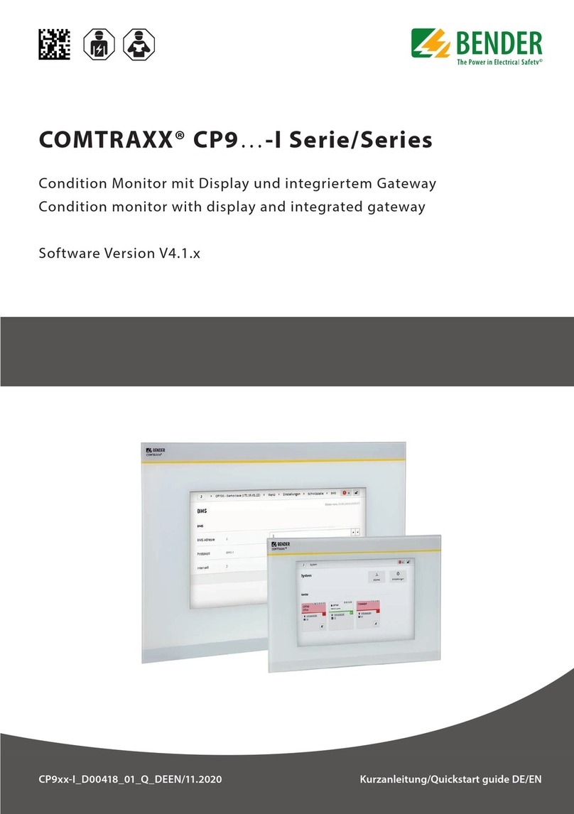
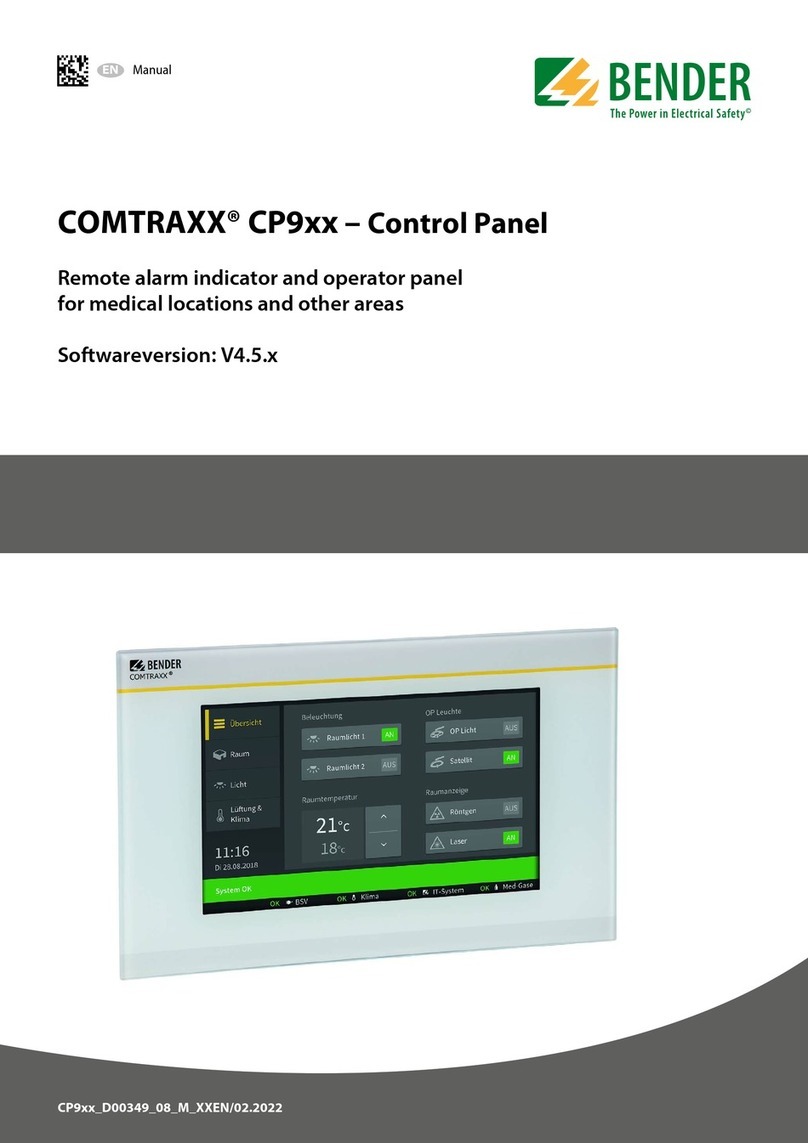
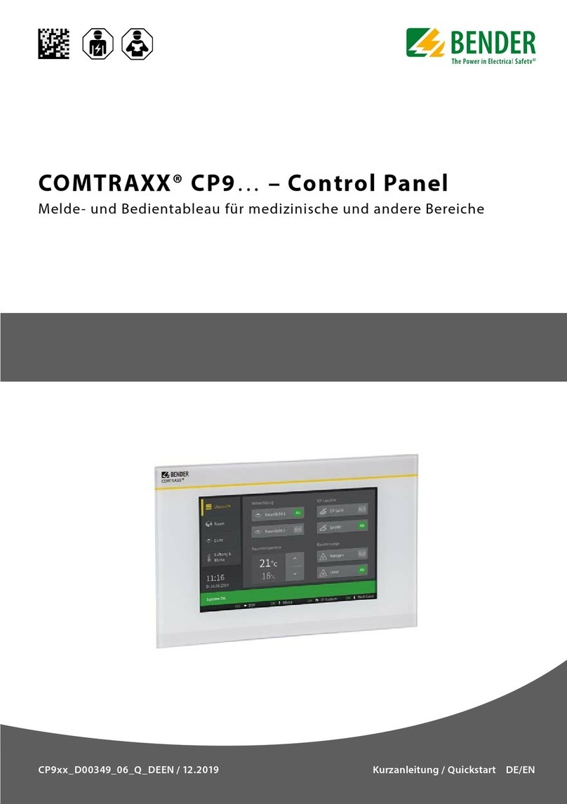
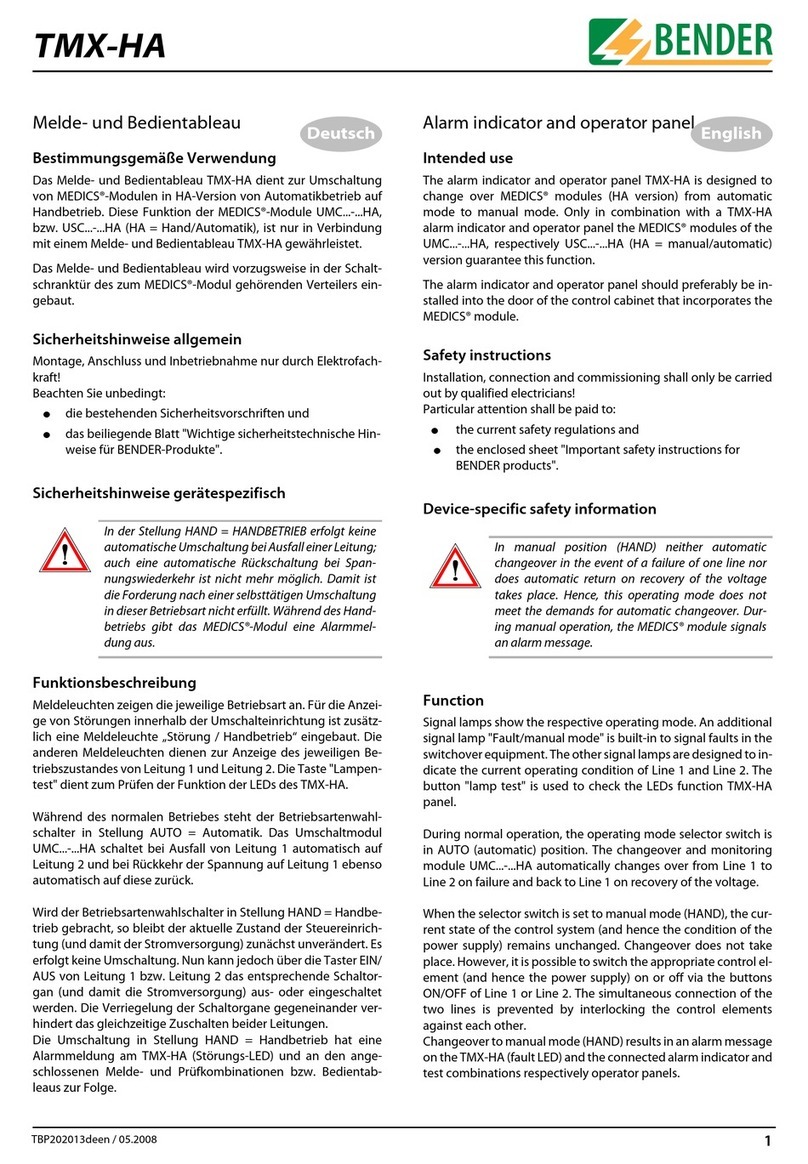
Bender COMTRAXX CP9 Series User manual

Breves instrucciones ES
Quick-start guide EN
CP9xx_D00349_09_Q_ESEN/01.2024
COMTRAXX® CP9xx – Control Panel
Paneles de control y de alarma para áreas de uso médico y otros recintos
Remote alarm indicator and operator panel for medical locations and other areas

2 CP9xx_D00349_09_Q_ESEN/01.2024
COMTRAXX® CP9xx – Control Panel
COMTRAXX®CP9xx
Remote alarm indicator and operator
Graphical interface for operation and monitoring of
medical and other technical installations.
This quick-start guide does not replace the manual!
Quick-start guide for the following devices
Scope of delivery
• CP9xx
• Safety instructions
• Quick-start guide DE/EN
For CP915 and CP924 additionally
• Connecting cable
• Ethernet-Keystone coupler
• USB cable
• RJ45 flat patch cable
Intended use
The device CP9xx is used wherever complex informa-
tion needs to be displayed easily and clearly for a user.
Due to its touch-sensitive surface, it can also be used as
a control option for installations.
Any other use than that described in this manual is re-
garded as improper.
Installation and connection
I Danger! Risk of fatal injury due to electric
shock!
Touching live parts of the system carries the risk of
electric shock. Before installing and connecting
the device, make sure that the installation has
been de-energised. Observe the rules for working
on electrical installations.
Manual
COMTRAXX® CP9xx
Paneles de control y de alarma
Interfaz gráfico para el manejo y la monitorización de
instalaciones médicas y otras
Estas breves instrucciones no sustituyen al manual.
Breve instrucciones para los siguientes aparatos
Tipo/
Type
Pantalla/
Display UsAN x A x F / W x H x D Peso/
Weight Ref./Art.-No. Manual No.
CP907 7“ (17,6 cm) DC 24V , < 15W; 226 x 144 x 78 mm 1.2 kg B95061080 (Frontal blanco/Front white)
D00349
CP915 15,6“ (38,6 cm) AC 100…240V, < 30W 505 x 350 x 95 mm 6.1 kg B95061081 (Frontal blanco/Front white)
95061085 (Frontal gris /Front grey)
CP924 24“ (61,0 cm) AC 100…240V, < 55W 654 x 441 x 100 mm 9.1 kg B95061183 (Frontal blanco /Front white)
B95061184 (Frontal gris/Front grey/grey)
Volumen de suministro
• CP9xx
• Instrucciones de seguridad
• Breves instrucciones ES/EN
Para CP915 y CP924 adicionalmente
• Cable de conexión
• Acoplador Ethernet-Keystone
• Cable USB
• Cable plano RJ45
Uso apropiado
El equipo CP9xx se utiliza allí donde sea necesaria la
representación sencilla y clara de informaciones com-
plejas para el usuario. Debido a la superficie sensible al
tacto se puede usar también como opción de control de
instalaciones.
Cualquier otro uso que no sea el descrito en este manual
se considera indebido.
Instalación y conexión
I ¡Peligro! Peligro de muerte por descarga eléc-
trical entrar en contacto con partes de la insta-
lación bajo tensión, existe riesgo de descarga
eléctrica. Antes de instalar el equipo y de realizar
trabajos en las conexiones, asegúrese de que la
instalación esté inactiva. Tenga en cuenta las
normas para la realización de trabajos en instala-
ciones eléctricas.
Manual

CP9xx_D00349_09_Q_ESEN/01.2024 3
COMTRAXX® CP9xx – Control Panel
I Caution!
Functional ground. The device must be earthed.
Without connection of the functional earth, the
device function is not guaranteed.
Electrostatic sensitive devices.
Observe precautions for handling electrostatic
sensitive devices.
Damage to components. Do not remove the de-
vice from the enclosure during ongoing operati-
on. First, disconnect the device from the supply
voltage and from the network (Ethernet).
Incorrect connector plugs. Connector plugs of
another devices may have a different polarity.
Please only use the supplied connector plug
(A1+/A/2-/PE).
Safe separation. The supply shall be properly se-
parated from hazardous voltages and meet the
limits of UL/CSA 61010-1, Clause 6.3.
Dimensions (mm)
Medidas del equipo / Device dimensions ±1
Tipo / Type a b c
CP907 226 144 176 (7”)
CP915 505 350 386 (15,6”)
CP924 654 441 610 (24”)
Dimensiones de instalación / Installation dimensions ±1
Tipo / Type a b
Profundidad de
montaje requerida /
Installation depth
CP907 Para empotrar en pared/
Flush-mounting 212 124 75
CP915 Para empotrar en pared/
Flush-mounting 464 309 92
CP924 Para empotrar en pared/
Flush-mounting 613 399 95
Dimensiones de la carcasa / Enclosure dimensions ±1
Tipo / Type A B C
CP907 Montaje empotrado/Flush-mounting 212 124 75
CP915 Montaje empotrado/Flush-mounting 461 306 92
CP924 Montaje empotrado/Flush-mounting 610 396 95
COMTRAXX®
a
cb
I ¡PreCauCión!
Tierra funcional. Es preciso conectar el equipo a
tierra. Sin una conexión de tierra funcional no se
garantiza la función del equipo.
Componentes sensibles a la electroestática.
Tenga en cuenta las instrucciones de seguridad en el
manejo de equipos sensibles a la electroestática.
Daños en componentes. No extraiga el equipo de
la envolvente durante su funcionamiento. Antes
debe desconectar el equipo de la tensión y de la
red (Ethernet).
Conectores erróneos. Los conectores de otros
equipos pueden tener una polaridad diferente.
Use únicamente el conector suministrado (A1+/
A2–/PE).
Desconexión segura. La fuente de alimentación
debe ser desconectada de manera apropiada de
tensiones peligrosas y cumplir con los valores
límite UL/CSA 6101010-1, cláusula 6.3.
Dimensiones (mm)
A
B
C

4 CP9xx_D00349_09_Q_ESEN/01.2024
COMTRAXX® CP9xx – Control Panel
I Caution! Damage to the display front
Placing the suction lifter in the middle and pulling
only at this point may damage the front plate.
Always place the suction lifter on the edges of the
display.
Connections on the mainboard CP9xx
* The CP907 can also be supplied via Power-over-Ethernet (PoE).
In this case the PoE switch must be earthed.
i
Use at least 75 °C copper conductors for UL appli-
cations!
Use at least 80 °C copper conductors for PoE.
I ¡Atención! Daños en la parte frontal de la pantalla
Si coloca la ventosa en el centro y tira de la parte
frontal, puede dañarla. Coloque siempre la vento-
sa en los bordes de la pantalla.
Conexiones a la placa principal CP9xx
Conector para entradas digitales 1Connector for digital Inputs
Interfaz I²C 2I²C-interface
Conector para placa de almacenamiento de energía 3Connector to energy storage board
Fuente de alimentación A1/+, A2/–, PE 4Voltage supply A1/+, A2/–, PE
Ethernet (RJ45 PoE)*; HTTP; ModbusTCP, BCOM 5Ethernet (RJ45 PoE)*; HTTP; ModbusTCP, BCOM
Enchufe X1-para Modbus RTU y BMS-Bus 6X1 plug for Modbus RTU and BMS-Bus
Terminación de Modbus RTU y BMS-Bus 7Termination of Modbus RTU and BMS-Bus
Conexiones USB (paraTouch Sensor) / CP907 descargado 8USB ports (for Touch Sensor) / CP907 unloaded
Entrada DVI / CP907 descargado 9DVI-Port / CP907 unloaded
Salida audio / CP907 descargado 10 Audio Output / CP907 unloaded
Entrada audio / CP907 descargado 11 Audio Inputs / CP907 unloaded
Conexión al relé de control 12 Connection to control relay
* La alimentación del CP907 también se puede realizar mediante Power-
over-Ethernet (PoE). En este caso, es obligatorio que el interruptor
PoE esté conectado a tierra.
i
Para aplicaciones UL utilizar al menos cables de
cobre 75 °C. Para PoE al menos 80 °C.
3
2
1
456
7
89
10 11
12

CP9xx_D00349_09_Q_ESEN/01.2024 5
COMTRAXX® CP9xx – Control Panel
SBMS
ABMS
BBMS
AMB BMB
SMB
SBMS
ABMS
BBMS
AMB BMB
SMB
Asignación conector X1 (7)
X1 plug connector (7)
1 2
3
4 5
6
7 8
9
10 11
12
LL
1 2
3
4 5
6
7 8
9
10 11
12
KK
Kx
Lx
N/O
Ky
Ly
N/C
x, y: 1...12
+24 V+24 V
0 V0 V
Asignación entradas digitales (1)
Assignment of digital inputs (1)
Terminación Modbus RTU y BMS-Bus (8)
Termination of Modbus RTU and BMS-bus (8)
Modbus RTU BMS-Bus
Relé de control / Control relay (13)
141211
Connection overview
Connections on the mainboard CP915 / CP924
Esquema de conexiones
Asignación de conectores
COMTRAXX®
1 2 12
...
11 12 14
Digital I/O
COMTRAXX®
Switch
+
–
~
LTE
Relais / Relay
USB
BMS-Bus
Modbus RTU
Ethernet
Ethernet (1:1)
US

6 CP9xx_D00349_09_Q_ESEN/01.2024
COMTRAXX® CP9xx – Control Panel
Commissioning
Required information before commissioning:
• DHCP server available for CP9xx and other
BCOM devices?
• Fixed IP addresses for Modbus devices
(e.g. IOM750-xxx)
• Subnet mask
• IP address of the standard gateway
• IP address of the DNS server
If a DHCP server is available in the network, the device
address can be assigned automatically.
Initial commissioning of screen
Entering a manual address:
• Switch on the supply voltage
• Enter the desired IP address for the CP9xx
• Enter the subnet mask of the LAN
• Enter the gateway address of the LAN
• Press the “Save” button to store the entries
• Wait 8…10 seconds
Activating address reception via a DHCP server
• Activate “DCHP?” checkbox
• Press the “Save” button to store the entries
• Wait 8…10 seconds
Login to the device
From a local network LAN
• Open a browser on a device (computer/laptop)
that is integrated into the network
• Enter the address indicated in line 1 of the CP9xx
into the address field of the browser
From a peer to peer network (1:1 connection)
It is possible to connect the CP9xx directly to a comput-
er/laptop. In this case, the CP9xx can be controlled with
a second fixed IP address.
• Open browser on the connected device
• Enter the following address into the address line
of the browser: 169.254.0.1
Puesta en marcha
Informaciones necesarias antes de la puesta en marcha:
• ¿Servidor DHCP disponible para CP9xx y otros
equipos BCOM?
• Direcciones IP fijas para equipos Modbus
(p. ej. IOM750-xxx)
• Máscara subred
• Dirección IP de pasarela estándar
• Dirección IP del servidor DNS
Si el servidor DHCP está disponible en red la dirección
del equipo se puede asignar de manera automática.
Puesta en marcha inicial de la pantalla
Introducción manual de una dirección:
• Conectar la fuente de alimentación
• Introducir Dirección IP para el CP9xx
• Introducir la submáscara del LAN
• Introducir la dirección de pasarela del LAN
• Guardar los datos introducidos pulsando el botón
“Save”
• Espere 8…10 segundos
Activación de la recepción de dirección de un
servidor DHCP
• Seleccione “DHCP?”“
• Guardar los datos introducidos pulsando el botón
“Save”
• Espere 8…10 segundos
Registro en el equipo
Desde una red local LAN
• Abrir el explorador en un equipo que esté integra-
do en la red (PC/portátil)
• Introducir la dirección indicada en la línea 1 del
CP9xx en el campo del explorador
A través de un PC directamente conectado (conexión 1:1)
Es posible conectar el CP9xx directamente a un PC /
portátil. En este caso, se puede controlar el CP9xx con
una segunda dirección fija IP.
• Abrir el explorador en el equipo conectado
• Introducir la siguiente dirección en el campo de
dirección del explorador: 169.254.0.1

CP9xx_D00349_09_Q_ESEN/01.2024 7
COMTRAXX® CP9xx – Control Panel
COMTRAXX® Start screen
Technical data
CP907
Display.......................................................................................7” (176 mm)
Front.....................................................................................glass, tempered
Supply voltage via A1/+; A2/-......................................... DC 24 V SELV/PELV
Supply via PoE
PoE standard ...................................................................... IEEE 802.3at
Nominal voltage ..........................................................DC 48 V, < 15 W
Max. cable length via AWG 26/7; 0.14 mm² ................................100 m
Dimensions......................................................................226 x 144 x 78 mm
Weight................................................................................................. 1.1 kg

CP915
Display.....................................................................................15” (386 mm)
Front................................................................. glass, tempered, white/grey
Supply voltage.......................................................AC 100…240 V / < 30 W
Dimensions......................................................................505 x 350 x 92 mm
Weight................................................................................................. 6.1 kg
CP924
Display.....................................................................................24” (610 mm)
Front................................................................. glass, tempered, white/grey
Supply voltage.......................................................AC 100…240 V / < 55 W
Dimensions....................................................................654 x 441 x 100 mm
Weight................................................................................................. 9.1 kg
Pantalla de inicio COMTRAXX®
TOOLS
ALARMS
BUS OVERVIEW
HOME
EN
System OK
DeviceName
1207990020-Bxxxxxxxx
Comtraxx CP900 V4.x
Device info
CP900
COMTRAXX®
DeviceName
20.12.2020 13:30 (+01:00)
Datos técnicos
CP907
Pantalla......................................................................................7“ (176 mm)
Frontal ............................................................................ cristal, atemperado
Tensión de alimentación.................................................. DC 24 V SELV/PELV
Alimentación mediante PoE
Norma PoE...........................................................................IEEE 802.3at
Tensión nominal ..........................................................DC 48 V, < 15 W
Longitud máx. del cable via AWG 26/7; 0,14 mm² ......................100 m
Medidas...........................................................................226 x 144 x 78 mm
Peso..................................................................................................... 1,1 kg
CP915
Pantalla....................................................................................15“ (386 mm)
Frontal ..........................................................cristal atemperado, blanco/gris
Tensión de alimentación........................................AC 100…240 V / < 30 W
Medidas...........................................................................505 x 350 x 92 mm
Peso..................................................................................................... 6,1 kg
CP924
Pantalla....................................................................................24“ (610 mm)
Frontal ..........................................................cristal atemperado, blanco/gris
Tensión de alimentación........................................AC 100…240 V / < 55 W
Medidas.........................................................................654 x 441 x 100 mm
Peso..................................................................................................... 9,1 kg

Bender GmbH & Co. KG
Londorfer Straße 65
35305 Grünberg
Germany
Tel.: +49 6401 807-0
info@bender.de
www.bender.de
© Bender GmbH & Co. KG, Germany
Subject to change! The specied
standards take into account the edition
valid until 01/2024 unless otherwise
indicated.
Alle Rechte vorbehalten.
Nachdruck und Vervielfältigung nur mit
Genehmigung des Herausgebers.
All rights reserved.
Reprinting and duplicating only with
permission of the publisher.
Other Order numbers
Spare parts
EU Declaration of Conformity
The full text of the EU Declaration of Conformity
is available via the QR Code:
Declaración de conformidad EU
El texto completo de la Declaración de Con-
formidad de la EU está disponible a través del
código QR:
Referencias
Repuestos
Equipo/Device Accesorio/Accessories Ref./ Art.-No.
CP907 Caja para empotrar/Flush-mounting enclosure B95100140
CP915
Pantalla, blanco/Displayunit, white B95061090
Pantalla, gris/Displayunit, grey B95061110
Caja para empotrar incl. placa de montaje con electrónica/
Flush-mounting enclosure with mounting plate and electronics B95061092
CP924
Pantalla, blanco/Displayunit, white B95061111
Pantalla, gris/Displayunit, grey B95061097
Caja para empotrar incl. placa de montaje con electrónica/
Flush-mounting enclosure with mounting plate and electronics B95061099
Todos/All CP9xx Kit conector de repuesto/CP9xx replacement plug connector kit B95061910
CP915
CP924 CP9xx Elevador de vacío/CP9xx vacuum lifter B95061911
solo/only CP907
B95100140
Other manuals for COMTRAXX CP9 Series
8
This manual suits for next models
3
Table of contents
Other Bender Control Panel manuals

Bender
Bender COMTRAXX CP9 Series User manual

Bender
Bender COMTRAXX CP9 Series User manual

Bender
Bender PRC487 User manual

Bender
Bender FP200 User manual

Bender
Bender COMTRAXX CP305 User manual

Bender
Bender COMTRAXX CP9 Series User manual

Bender
Bender COMTRAXX CP9 Series User manual

Bender
Bender COMTRAXX CP9 Series User manual

Bender
Bender COMTRAXX CP9 Series User manual

Bender
Bender TM800 User manual