Bender COMTRAXX CP9 Series User manual

Kurzanleitung / Quickstart DE/ENCP9xx_D00349_06_Q_DEEN / 12.2019
COMTRAXX® CP9…– Control Panel
Melde- und Bedientableau für medizinische und andere Bereiche

2 CP9xx_D00349_06_Q_DEEN / 12.2019
COMTRAXX® CP9… – Control Panel
i
Bestandteil der Gerätedokumentation sind neben
dieser Kurzanleitung die beiliegenden „Sicher-
heitshinweise für Bender-Produkte“ und das
Handbuch, herunterladbar unter https://www.ben-
der.de/service-support/downloadbereich. Die
Kurzanleitung ersetzt nicht das Handbuch.
Bestimmungsgemäße Verwendung
Das Gerät CP9xx findet überall Einsatz, wo komplexe
Informationen für einen Anwender einfach und über-
schaubar dargestellt werden sollen. Durch die berüh-
rungsempfindliche Fläche dient es auch als
Steuerungsmöglichkeit von Anlagen.
Eine andere oder darüber hinausgehende Benutzung
gilt als nicht bestimmungsgemäß.
Sicherheitshinweise allgemein.
I VORSICHT! Funktionserde. Das Gerät ist zwin-
gend zu erden. Ohne Anschluss der Funktions-
erde ist die Gerätefunktion nicht gewährleistet.
Elektrostatisch gefährdete Bauelemente. Be-
achten Sie die Vorsichtsmaßnahmen für den
Umgang mit elektrostatisch gefährdeten Gerä-
ten.
Beschädigung von Bauteilen. Nehmen Sie das
Gerät nicht im laufenden Betrieb aus dem Ge-
häuse. Trennen Sie vorher das Gerät von der
Versorgungsspannung und vom Netzwerk
(Ethernet).
Falsche Anschlussstecker. Anschlussstecker
anderer Geräts können eine abweichende Po-
lung aufweisen. Verwenden Sie nur den beige-
legten Anschlussstecker (A1+/A2–/PE).
Sichere Trennung. Die Stromversorgung muss
ordnungsgemäß von gefährlichen Spannun-
gen getrennt sein und die Grenzwerte der
UL/CSA 6101010-1, Klausel 6.3 erfüllen.
COMTRAXX® CP9…
Graphical interface for operation and monitoring of
medical and other technical installations.
Quickstart for following devices:
COMTRAXX®CP9…
Grafikschnittstelle zur Bedienung und Überwachung
von medizinischen und anderen technischen Anlagen.
Kurzanleitung für folgende Geräte:
Type Display Supply voltage Us* B x H x T /W x H x D Weight Art.-No.
CP907 7“ (17,6 cm) DC 24V , < 15 W; 226 x 144 x 78 mm 1,2 kg B95061080 (Front white)
CP915 15,6“ (38,6 cm) AC 100…240V, < 30 W 505 x 350 x 95 mm 6,1 kg B95061081 (Front white)
B95061085 (Front grey)
CP924 24“ (54,5 cm) AC 100…240V, < 55 W 654 x 441 x 100 mm 9,1 kg comming soon
i
Part of the device documentation in addition to
this quickstart is the enclosed “Safety instructions
for Bender products“ and the manual, downloada-
ble at https://www.bender.de/en/service-support/
downloads. The quick-start guide does not replace
the operating manual.
Intended use
The Device CP9xx is used wherever complex informa-
tion needs to be displayed easily and clearly for a
user. Due to its touch-sensitive surface, it can also be
used as a control option for installations.
Any other use than that described in this manual is
regarded as improper.
General safety instructions
I CAUTION! Functional ground. The device must
be earthed. Without connection of the functio-
nal earth, the device function is not guaran-
teed.
Electrostatic sensitive devices. Observe pre-
cautions for handling electrostatic sensitive de-
vices.
Damage to components. Do not remove the
device from the enclosure during ongoing ope-
ration. First, disconnect the device from the
supply voltage and from the network (Ether-
net).
Incorrect connector plugs. Connector plugs of
another devices may have a different polarity.
Please only use the supplied connector plug
(A1+/A/2-/PE).
Safe separation. The supply shall be properly
separated from hazardous voltages and meet
the limits of UL/CSA 61010-1, Clause 6.3.

COMTRAXX® CP9… – Control Panel
CP9xx_D00349_06_Q_DEEN / 12.2019 3
Montage und Anschluss
I GEFAHR! Lebensgefahr durch Stromschlag! Bei
Berühren von unter Spannung stehender
Anlagenteile besteht die Gefahr eines elektri-
schen Schlages. Stellen Sie vor Einbau des
Gerätes und vor Arbeiten an den Anschlüssen
des Gerätes sicher, dass die Anlage spannungs-
frei ist. Beachten Sie die Regeln für das Arbeiten
an elektrischen Anlagen.
Gerätemaße
mm ±1 CP 907 CP 915 CP 924
a226 505 654
b144 350 441
c176 386 545
Maße Wandausschnitt
Dimensions wall cut-out
mm ±1 CP 907 CP 915 CP 924
Breite /Width 212 462 612
Höhe / Height 124 308 400
Tiefe / Depth 75 92 95
COMTRAXX®
a
cb
Installation and connection
I RISK of fatal injury due to electric shock!
Touching live parts of the system carries the risk
of electric shock. Before installing and connec-
ting the device, make sure that the installation
has been de-energised. Observe the rules for
working on electrical installations.
Device dimensions
Installation flush-mounting box CP907Wandeinbaukasten CP907
212
377
75 216
124
128
Wandeinbaukasten CP915 / CP924 Installation flush-mounting box CP915 / 924
92 / 95
306 / 398
461 / 610
Maße in mm / Dimensions in mm
Maße in mm / Dimensions in mm

4 CP9xx_D00349_06_Q_DEEN / 12.2019
COMTRAXX® CP9… – Control Panel
Anschlussübersicht
COMTRAXX®
1 2 12
...
11 12 14
Digital I/O
COMTRAXX®
+
–
~
Relais / Relay
USB
BMS-Bus
Modbus RTU
Ethernet
Ethernet (1:1)
Connections on the mainboard CP9...
Legend
1Connector for digital Inputs
2I²C-interface
3Connector to energy storage board
4Backbone Bus (unloaded)
5Voltage supply A1/+, A2/–, PE
6Ethernet (RJ45 PoE); HTTP; ModbusTCP, BCOM
7X1 plug for Modbus RTU and BMS-Bus
8Termination of Modbus RTU and BMS-Bus
9USB ports (for Touch Sensor) / CP907 unloaded
10 DVI-Port / CP907 unloaded
11 Audio Output / CP907 unloaded
12 Audio Inputs / CP907 unloaded
13 Connection to control relay
i
For UL applications use at least 75 °C copper lines!
Use at least 80°C copper lines for PoE.
Anschlüsse an die Hauptplatine CP9...
Legende
1Steckbuchse für digitale Eingänge
2I²C-Schnittstelle
3Steckbuchse zur Energiespeicherplatine
4Backbone Bus (nicht bestückt)
5Spannungsversorgung A1/+, A2/–, PE
6Ethernet (RJ45 PoE); HTTP; ModbusTCP, BCOM
7X1-Stecker für Modbus RTU und BMS-Bus
8Terminierung von Modbus RTU und BMS-Bus
9USB-Anschlüsse (fürTouch Sensor) / CP907 nicht bestückt
10 DVI-Eingang / CP907 nicht bestückt
11 Audio Ausgang / CP907 nicht bestückt
12 Audio Eingang/ CP907 nicht bestückt
13 Anschluss Steuerrelais
i
Für UL-Anwendungen mind. 75°C-Kupferleitungen
verwenden! Für PoE mind. 80°C-Kupferleitungen
verwenden.
Connectionoverview
1
2
3
5
6
7
8
13
11
10
9
4
12

COMTRAXX® CP9… – Control Panel
CP9xx_D00349_06_Q_DEEN / 12.2019 5
Belegung der Steckanschlüsse
Inbetriebnahme
Benötigte Informationen VOR einer Inbetriebnahme:
• DHCP-Server verfügbar für CP9… und andere
BCOM- Geräte?
• Feste IP-Adressen für Modbus-Geräte
(z. B. IOM750-xxx)
• Subnetz-Maske
• IP-Adresse vom Standard-Gateway
• IP-Adresse vom DNS-Server
Ist ein DHCP-Server im Netzwerk vorhanden, kann die
Adressierung des Geräts automatisch vorgenommen
werden.
Bildschirm Erstinbetriebnahme
Eingabe einer manuellen Adresse:
• Spannungsversorgung einschalten
• IP-Adresse für das CP9… eingeben
• Subnetzmaske des LAN eingeben
• Gatewayadresse des LAN eingeben
• Eingaben speichern mit der „Save“-Taste
• Warten Sie 8-10 Sekunden
Aktivierung des Adressempfangs von einem DHCP-
Server
• Aktivieren Sie „DHCP?“
• Eingaben speichern mit der „Save“-Taste
• Warten Sie 8-10 Sekunden
SBMS
ABMS
BBMS
AMB BMB
SMB
SBMS
ABMS
BBMS
AMB BMB
SMB
Belegung X1-Stecker (7)
X1 plug connector (7)
1 2
3
4 5
6
7 8
9
10 11
12
LL
1 2
3
4 5
6
7 8
9
10 11
12
KK
...
K1
L1
N/O
K2
L2
N/C
K12
L12
N/O
Belegung digitale Eingänge (1)
Assignment of digital inputs (1)
Terminierung Modbus RTU und BMS-Bus (8)
Termination of Modbus RTU and BMS-bus (8)
Modbus RTU BMS-Bus
Steuerrelais / Control relay (13)
141211
Connections on the mainboard CP915
Commissioning
Required information BEFORE commissioning:
• DHCP server available for CP9… and other
BCOM devices?
• Fixed IP addresses for Modbus devices
(e.g. IOM750-xxx)
• Subnet mask
• IP address of the standard gateway
• IP address of the DNS server
If a DHCP server is available in the network, the device
address can be assigned automatically.
Initial commissioning of screen
Entering a manual address:
• Switch on the supply voltage
• Enter the desired IP address for the CP9…
• Enter the subnet mask of the LAN
• Enter the gateway address of the LAN
• Press the „Save“ button to store the entries
• Wait 8-10 seconds
Activating address reception via a DHCP server
• Activate „DCHP?“ checkbox
• Press the „Save“ button to store the entries
• Wait 8-10 seconds

6 CP9xx_D00349_06_Q_DEEN / 12.2019
COMTRAXX® CP9… – Control Panel
Anmeldung am Gerät
Aus einem lokalen Netzwerk LAN
• Öffnen Sie einen Browser auf einem im Netzwerk
eingebundenen Gerät (Computer/Laptop)
• Geben Sie im Adressfeld des Browsers die Adresse
der 1. Zeile des CP9… ein
Mittels direkt verbundenem PC (1:1-Verbindung)
Es ist möglich das CP9… direkt mit einem Computer/
Laptop zu verbinden. In diesem Falle lässt sich das
CP9… über eine zweite feste IP-Adresse ansteuern.
• Browser auf verbundenem Gerät öffnen
• Geben Sie in der Adresszeile des Browsers folgende
Adresse ein: 169.254.0.1
COMTRAXX® Startbildschirm
TOOLS
ALARMS
BUS OVERVIEW
HOME
EN
System OK
Text
1207990020-Bxxxxxxxx
Comtraxx CP900 V3.0
Device info
CP900
COMTRAXX®
Text ...
18.07.2017 13:30
Login to the device
From a local network LAN
• Open a browser on a device (computer/laptop)
that is integrated into the network
• Enter the address indicated in line 1 of the CP9…
into the address field of the browser
From a peer to peer network (1:1 connection)
It is possible to connect the CP9… directly to a com-
puter/laptop. In this case, the CP9… can be controlled
with a second fixed IP address.
• Open browser on the connected device
• Enter the following address into the address line of
the browser: 169.254.0.1
COMTRAXX® Start screen

COMTRAXX® CP9… – Control Panel
CP9xx_D00349_06_Q_DEEN / 12.2019 7
Technische Daten
CP907
Display.....................................................................7“ (176 mm)
Front......................................................................Glas, gehärtet
Versorgungsspannung...............................DC 24 V, PoE, < 15 W
Maße..............................................................226 x 144 x 78 mm
Gewicht.............................................................................. 1,1 kg
CP915
Display...................................................................15“ (386 mm)
Front ................................................... Glas, gehärtet, weiß/grau
Versorgungsspannung........................ AC 100…240 V / < 30 W
Maße..............................................................505 x 350 x 92 mm
Gewicht...............................................................................6,1kg
CP924
Display...................................................................24“ (545 mm)
Front......................................................................Glas, gehärtet
Versorgungsspannung........................ AC 100…240 V / < 55 W
Maße............................................................654 x 441 x 100 mm
Gewicht.............................................................................. 9,1 kg
Weitere Bestellnummern
Ersatzteile
Gerät Zubehör Bestellnummer
CP907 UP-Gehäuse B95100140
CP915 Displayeinheit, weiß B95061090
Displayeinheit, grau B95061110
UP-Gehäuse incl. Montageplatte mit
Elektronik
B95061092
CP924 Displayeinheit, weiß Demnächst
Displayeinheit, grau Demnächst
UP-Gehäuse incl. Montageplatte mit
Elektronik
Demnächst
alle CP9… Ersatz-Steckerkit B95061910
CP915/24 CP9… Saugheber B95061911
Technical data
CP907
Display.................................................................... 176 mm (7“)
Front...................................................................glass, tempered
Supply voltage...........................................DC 24 V, PoE, < 15 W
Dimensions....................................................226 x 144 x 78 mm
Weight............................................................................... 1.1 kg
CP915
Display...................................................................381 mm (15“)
Front...............................................glass, tempered, white/grey
Supply voltage.................................... AC 100…240 V / < 30 W
Dimensions....................................................505 x 350 x 92 mm
Weight................................................................................6.1kg
CP924
Display...................................................................545 mm (24“)
Front...................................................................glass, tempered
Supply voltage.................................... AC 100…240 V / < 55 W
Dimensions..................................................654 x 441 x 100 mm
Weight............................................................................... 9.1 kg
Other Order numbers
Spare parts
Device Accessories Order number
CP907 Flush-mounting enclosure B95100140
CP915 Displayunit, white B95061090
Displayunit, grey B95061110
Flush-mounting enclosure with
mounting plate and electronics
B95061092
CP924 Displayunit, white comming soon
Displayunit, grey comming soon
Flush-mounting enclosure with
mounting plate and electronics
comming soon
All CP9… replacement plug connector kit B95061910
CP915/24 CP9… vacuum lifter B95061911

Alle Rechte vorbehalten.
Nachdruck und Vervielfältigung
nur mit Genehmigung des Herausgebers.
Bender GmbH & Co. KG
Postfach 1161 • 35301 Grünberg • Deutschland
Londorfer Str. 65 • 35305 Grünberg • Deutschland
Tel.: +49 6401 807-0 • Fax: +49 6401 807-259
All rights reserved.
Reprinting and duplicating
only with permission of the publisher.
Bender GmbH & Co. KG
PO Box 1161 • 35301 Gruenberg • Germany
Londorfer Str. 65 • 35305 Gruenberg • Germany
Tel.: +49 6401 807-0 • Fax: +49 6401 807-259
CP9xx_D00349_06_Q_DEEN / 12.2019/ pdf / © Bender GmbH & Co. KG, Germany – Subject to change!The specied standards take into account the edition valid until 11/2019 unless otherwise indicated.
Other manuals for COMTRAXX CP9 Series
8
This manual suits for next models
3
Table of contents
Other Bender Control Panel manuals
Bender
Bender TMX-HA User manual
Bender
Bender COMTRAXX CP305 User manual
Bender
Bender FP200 User manual
Bender
Bender PRC487 User manual
Bender
Bender COMTRAXX CP305 User manual
Bender
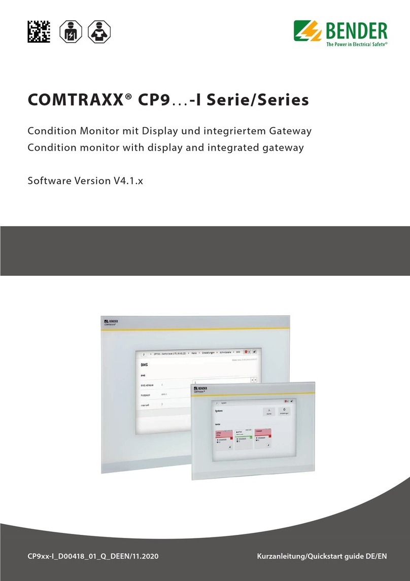
Bender COMTRAXX CP9 I Series User manual
Bender
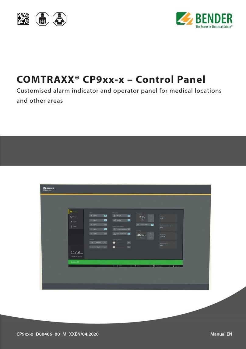
Bender COMTRAXX CP9 Series User manual

Bender
Bender COMTRAXX CP9 Series User manual
Bender
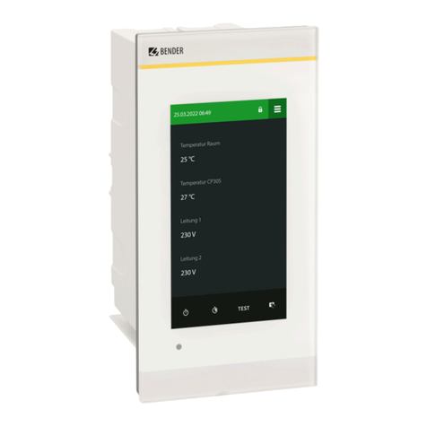
Bender COMTRAXX CP305 User manual
Bender
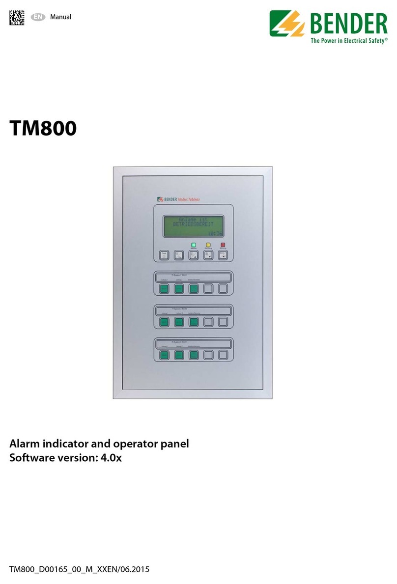
Bender TM800 User manual


