Sullair 02250160-842 User manual

WS CONTROLLER
INSTRUCTION
MANUAL
Part Number
02250160-842
©Sullair Corporation
KEEP FOR
FUTURE
REFERENCE

AIR CARE SEMINAR
TRAINING
Sullair Air Care Seminars are courses that provide hands-on instruction in the proper operation, maintenance
and service of Sullair equipment. Individual seminars on Industrial compressors and compressor electrical
systems are presented at regular intervals throughout the year at a dedicated training facility at Sullair’s
corporate headquarters in Michigan City, Indiana.
Instruction includes discussion of the function and installation of Sullair service parts, troubleshooting of the
most common problems, and actual equipment operation. The seminars are recommended for maintenance
and service personnel.
For detailed course outlines, schedule and cost information contact:
Sullair Corporate Training Department
1-888-SULLAIR or 219-879-5451 (ext. 5363)
www.sullair.com
Or Write -
Sullair Corporation
3700 E. Michigan Blvd.
Michigan City, IN 46360
Attn: Service Training Department

TABLE OF CONTENTS
1. SAFETY.............................................................................................................................................................. 1
1.1 INTRODUCTION....................................................................................................................................... 1
1.2 ELECTRICAL SHOCK .............................................................................................................................. 1
1.3 VARIABLE SPEED DRIVE........................................................................................................................ 1
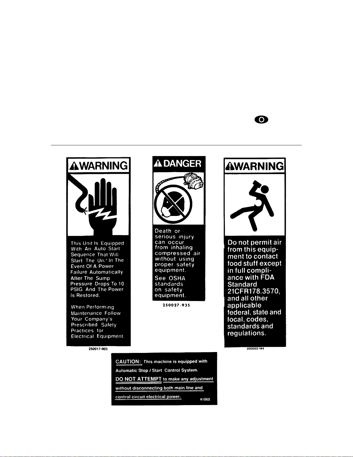
1.4 DECALS.................................................................................................................................................... 1
1.5 EMERGENCY STOP ................................................................................................................................ 2
2. STARTUP PROCEDURES................................................................................................................................. 5
2.1 INTRODUCTION....................................................................................................................................... 5
2.2 WS CONTROLLER PANEL LAYOUT....................................................................................................... 5
2.3 WS START UP PROCEDURES ............................................................................................................... 6
2.3.1 COMPRESSOR MOTOR ROTATION DIRECTION CHECK (at installation)................................ 6
2.3.2 FAN MOTOR ROTATION CHECK (at installation) ....................................................................... 6
2.3.3 INITIAL START-UP AFTER INSTALLATION................................................................................ 6
2.3.4 SUBSEQUENT START-UP PROCEDURE................................................................................... 7
2.4 SHUTDOWN PROCEDURE..................................................................................................................... 7
3. ADJUSTMENTS ................................................................................................................................................. 9
3.1 INTRODUCTION....................................................................................................................................... 9
3.2 COMPRESSOR ADJUSTMENT PROCEDURES..................................................................................... 9
3.3 USER ADJUSTABLE CONTROL PARAMETERS.................................................................................. 10
3.4 CALIBRATION OF P2 PRESSURE TRANSDUCERS ........................................................................... 12
3.5 REMOTE UNLOAD................................................................................................................................. 12
4. WS CONTROLLER DESCRIPTION................................................................................................................. 13
4.1 INTRODUCTION..................................................................................................................................... 13
4.2 TOUCH PAD BUTTON DESCRIPTION.................................................................................................. 13
4.3 INDICATOR LED DESCRIPTION........................................................................................................... 13
4.4 DISPLAY SCREEN................................................................................................................................. 14
4.4.1 NORMAL VIEW ........................................................................................................................... 14
4.4.2 COMPRESSOR STATUS VIEW ................................................................................................. 14
4.4.3 COMPRESSOR ADJUSTMENT VIEW – CONTROL PARAMETERS........................................ 15
4.5 OPERATING MODES............................................................................................................................. 15
4.6 OPERATING STATES............................................................................................................................ 16
4.7 NORMAL VIEW SERVICE REMINDERS............................................................................................... 18
4.8 WARNING MESSAGES.......................................................................................................................... 18
4.9 FAULT MESSAGES................................................................................................................................ 19
5. TROUBLESHOOTING...................................................................................................................................... 21
5.1 TROUBLESHOOTING INTRODUCTION ............................................................................................... 21
5.2 TROUBLESHOOTING GUIDE................................................................................................................ 22
5.3 MACHINE BEHAVIOR AFTER A POWER Interruption.......................................................................... 24
TELEPHONES, FAX AND ADDRESSES.......................................................................................... BACK COVER
OPERATOR IS REQUIRED TO READ
ENTIRE INSTRUCTION MANUAL


Section 1
SAFETY
1
1. SAFETY
1.1 INTRODUCTION
Sullair Corporation and its subsidiaries design and manufacture all of their products so
they can be operated safely. However, the responsibility for safe operation rests with
those who use and maintain these products. For safe machine operation it is vitally
important to review all safety precautions noted in the Safety Section of the compressor’s
Operator’s Manual. The precautions listed in the Operator’s Manual, as well as those
noted here are offered as a guide which, if conscientiously followed, will minimize the
possibility of accidents throughout the useful life of this equipment.
The compressor should be operated only by persons who have been trained and
delegated to do so, and who have read and understood this manual and the compressor
Operator’s Manual. Failure to follow the instructions, procedures and safety precautions
listed here and in the Operator’s Manual may result in accidents and injuries.
NEVER start the compressor unless it is safe to do so.
DO NOT attempt to operate the compressor with a known unsafe condition. Tag the
compressor and render it inoperative by disconnecting and locking out all power at the
source, or disable its prime mover so others who may not know of the unsafe condition
cannot attempt to operate it until the condition is corrected. Use and operate the air
compressor only in full compliance with all pertinent OSHA requirements or any pertinent
Federal, State, and Local codes or requirements.
DO NOT modify the compressor and/or controls in any way except with written factory
approval.
1.2 ELECTRICAL SHOCK
A. Keep all parts of the body, any hand-held tools, or other conductive objects away
from exposed live wiring and components of the electrical system. Maintain dry
footing, stand on insulated surfaces and DO NOT contact any other portion of the
compressor when making adjustments or repairs to exposed live components of the
electrical system.
All field equipment must be tested for electrostatic fields prior to servicing or
making contact with the machine using the following or equivalent test
equipment:
• 90-600 VAC : Volt detector such as Fluke Model 1AC-A
• 600-7000 VAC : Voltage detector such as Fluke Networks Model C9970
It is the responsibility of each organization to provide/arrange trainng for all
their associates expected to test for electrostatic fields.
B. Attempt repairs only in clean, dry, well lighted and well ventilated areas.
C. Stay clear of the compressor during electrical storms.
1.3 VARIABLE SPEED DRIVE
Refer to Section 7 for safety information on variable speed drive products.
1.4 DECALS
The WS Controller panel displays several decals which provide necessary information for
safe performance. See Figures 1.1A and 1.1B. These decals should never be removed

Section 1
SAFETY
2
or modified. If a decal becomes damaged, contact your nearest Sullair Distributor or the
Sullair Corporation factory Service Department for replacement parts.
Note: When ordering new decals, use part number printed on the decal face.
1.5 EMERGENCY STOP
A large red Emergency Stop (E-STOP) button is located near the controller panel. Press
the E-STOP button in the event of an emergency to immediately shutdown the machine
and override all controller functions. The E-STOP button must be reset prior to restarting
the machine. When hazardous conditions no longer exist, reset the E-STOP by turning
the button ½ turn to the right. The button will release. Press the Stop pad to reset
the controls. The machine will be ready for restart.
Figure 1.1A Safety Decals and Part Numbers

Section 1
SAFETY
3
Figure 1.1B Safety Decals and Part Numbers
1 decal, warning auto start 250017-903 1
2 decal, danger breath air (I) 250027-935 1
3 sign, warning “food grade” lube 250003-144 1
4 decal, auto start 041065 1
(I) OSHA and FDA guidelines are superseded by any Federal, State or Local regulations
whenever applicable.

Section 1
SAFETY
4
NOTES

Section 2
STARTUP PROCEDURES
5
2. STARTUP PROCEDURES
2.1 INTRODUCTION
This compressor is equipped with an WS Controller for controlling the compressor
system operation, setting the machine parameters and performing maintenance
operations. The WS Controller is designed for the safe operation and protection of the
compressor system. When fault conditions occur, the controller automatically shuts down
the machine before the conditions can cause damage to the equipment. The WS
Controller also contains features that enable sequential interface with other machines.
2.2 WS CONTROLLER PANEL LAYOUT
The WS Controller panel is shown in Figure 2.1. The controller panel consists of :
•Display Screen for displaying machine status
•START pad for machine startup
•STOP pad for stopping machine operation and for clearing fault messages
while the machine is stopped
•UP arrow and DOWN arrow pads for navigation through the various panel
displays and for changing parameter values
•ENTER pad for selecting and accessing various screen displays and for entering
values
•Machine status indicator lights for identifying the current machine operational status.
Each of the controller components and functions is described in detail in Section 4.
Figure 2.1 WS Controller Panel
FAULT
INDICATOR
(RED)
START
PAD
UP ARROW
PAD
MAINTENANCE
INDICATOR
(AMBER)
DOWN
ARROW
PAD
AUTO MODE
INDICATOR
(GREEN)
POWER ON
INDICATOR
(GREEN)
DISPLAY
SCREEN
STOP
PAD
ENTER
PAD

Section 2
STARTUP PROCEDURES
6
2.3 WS START UP PROCEDURES
2.3.1 COMPRESSOR MOTOR ROTATION DIRECTION CHECK (at installation)
After the compressor has been installed and the electrical wiring is completed, perform
following steps to verify the direction of the compressor motor rotation.
1. If the display screen shows “AUTOMATIC”, press the UP arrow pad twice to
navigate to the Mode parameter. Press the ENTER pad. The screen will display
reverse characters indicating change mode is active. Press the down arrow pad
to highlight the “MANUAL” selection (it will appear in reverse text in the display).
Press the ENTER pad to accept the change and place the machine in the Manual
operating mode.
2. Press the START and STOP pads in succession to “bump start” the
compressor.
3. Observe the direction of the compressor motor shaft. When looking at the motor
from the end opposite the compressor unit, the shaft should be turning clockwise on
all gear driven models, and counterclockwise on direct drive models. A “Direction of
Rotation” decal is located on the coupling guard between the motor and compressor
to show proper motor/compressor rotation.
4. If the motor shaft is not turning in the proper direction, disconnect the power to the
starter and exchange any two of the three power input leads. Refer to the
Compressor Operator’s Manual.
5. Perform above steps 1 - 3 again to confirm proper motor/compressor rotation.
Variable speed drive ( VSD) packages do not require a main motor direction
check since the variable speed motor is set at the time of manufacture.
NOTE
2.3.2 FAN MOTOR ROTATION CHECK (at installation)
Verify the correct fan motor rotation using the following steps:
1. With the compressor running, visually check that the fan rotation is correct.
2. If it is incorrect, change the direction of the fan motor by disconnecting power from
the compressor.
3. Exchange any two of the three fan motor leads at the fan motor starter. Refer to the
compressor Operator’s Manual.
4. Recheck the direction of the fan motor.
2.3.3 INITIAL START-UP AFTER INSTALLATION
Perform the following procedure at the initial start-up of the compressor following
installation.
1. Verify that all preparations and checks necessary for proper installation have been
made. Refer to the compressor Operator’s Manual.
2. Read the preceding pages of this manual thoroughly.

Section 2
STARTUP PROCEDURES
7
3. Slowly open the shut-off valve to the service line.
4. Press the START pad to start the compressor. Compressor will begin
operating in the default mode (Automatic) set at the factory.
5. Check for possible leaks in piping.
6. Slowly close the service line shut-off valve to verify nameplate pressure unload
setting is correct. The compressor should unload when nameplate pressure is
achieved. If adjustments are necessary, see compressor Operator’s Manual.
7. Observe the operating temperature. Refer to compressor Operator’s Manual for
acceptable operating range. If temperature exceeds this range, check the cooling
system and installation environment.
8. Open the shut-off valve to the service line.
9. After operating the machine for 24 hours, inspect the compressor for oil leaks and
proper operating temperature.
2.3.4 SUBSEQUENT START-UP PROCEDURE
1. On subsequent start-ups, check the fluid sight glass for proper fluid level. Service if
necessary. See compressor Operator’s Manual.
2. Press the START pad on the display screen. The machine will prepare to start
up in the last operating mode existing at shutdown. The current Machine mode will
appear on the display screen.
3. If a different operating mode is desired, use the arrow pads to navigate to the Mode
parameter. Press the ENTER pad to enter the Change Mode. Navigate to the
desired mode (Automatic or Manual). Press the ENTER pad to accept and save
the mode setting.
4. When the compressor is running, observe the display panel and maintenance
indicators to ensure the values displayed are within the proper ranges.
2.4 SHUTDOWN PROCEDURE
Shut down the compressor by pressing the STOP pad on the WS Controller
panel.
The system may require sump blowdown (typically below 10 psi) to be
completed prior to restarting.
NOTE
The compressor may restart automatically after a power failure or after the E-Stop button
has been reset.

Section 2
STARTUP PROCEDURES
8
NOTES

Section 3
ADJUSTMENTS
9
3. ADJUSTMENTS
3.1 INTRODUCTION
This section describes steps for using the WS Controller to modify specific parameters
that control the machine operation.
NOTE
Control parameters described in this manual are those which can be adjusted
via the WS Controller. Additional parameters that control the operation the
compressor and sequencing of multiple machines can be viewed and edited
using the WS PC User Interface. See the WS PC User Interface Manual fo
r
more details.
Typically, the top line of the Controller Display Screen will display the line pressure and
compressor temperature; the bottom line will display the current operating mode. As the
user presses the down navigation arrow, the screen will display various machine
statistics appearing under the heading “Compressor Status”. These values are not
adjustable at the WS Controller. Navigating past these screens, the first line of the
screen will display the words “Show Settings-------“. This indicates that the controller is in
the Adjustment mode. When in Adjustment mode, control parameters will be described
in the second line of the display screen. These control parameters can be modified by
the user. The bottom line of the display will show the current value or setting of the
control parameter.
Section 3.2 provides general steps to modifying the compressor control parameters. A
description of each user modifiable parameter is provided in Section 3.3.
3.2 COMPRESSOR ADJUSTMENT PROCEDURES
The following steps apply while “Show Setting------- “ is indicated in the display. The
control parameter described in the display can be modified by the user. Use these steps
to modify a parameter value:
1. Press the UP arrow or DOWN arrow pad on the controller panel to navigate to
the parameter to be change.
2. Press the ENTER pad to select the parameter and access the CHANGE mode.
The change mode is indicated by the text “Change Setting -------” appearing in
reverse (negative) characters on the top line of the display. The parameter name will
appear on the second line and the current parameter value or setting will appear in
reverse characters on the bottom line.
3. Use the UP arrow or DOWN arrow pad to change the value or mode of the
parameter.
4. When the desired value or mode name appears on the display, Press ENTER to
accept and save this new value for the selected parameter. The display will return to
the ADJUSTMENT view and the new value or mode will be displayed.
5. Press the START pad to return the display to the NORMAL view.

Section 3
ADJUSTMENTS
10
3.3 USER ADJUSTABLE CONTROL PARAMETERS
Listed below are descriptions of the parameter that can be adjusted at the WS Controller:
Unload Pressure - Set point (psi, bar, or kpa) at which the system pressure will begin
unloading. For example if this parameter is set to 110 psi (7.6 bar) the machine will
unload when the line pressure is above 110 psi (7.6 bar).
Load Delta Pressure - The pressure differential (psi, bar, or kpa) below the unload
pressure at which the machine will begin loading. For example if the unload pressure
is set to 110 psi (7.6 bar) and the load differential is set to 10 psid (0.7 bar), the
machine will load when the line pressure goes below 100 psi (6.9 bar).
VSD Setpoint Pressure - (VSD packages only) The targeted pressure (psi, bar, or
kpa) for the variable speed controls. This is normally adjusted near the bottom of the
load/unload band above. The speed will be adjusted to maintain this pressure. Refer
to Section 7 for additional details.
Unload Minutes - Set time that the machine will run unloaded in Auto mode before
shutting off. If the time is set less than 15 minutes (for example 5), there may be times
when the machine will run unloaded for more than 15 minutes. This is because there is
another timer that keeps the machine from being started more than four times an hour.
This secondary timer is disabled when a machine is configured for VSD motor control.
Drain Interval Mins. - Set interval in minutes between activation of the drain cycle for
machines equipped with an electric solenoid drain. This does not apply to the Sullair
SCD zero loss drain, which is not controlled or monitored by the WS Controller.
Drain Time Seconds - Set time in seconds that the drain remains energized.
Wye Delta Seconds - Set time for wye to delta starter transition. Also used to control
the closed inlet start valve. Disable by setting to zero (0), standard for full voltage start.
Requires approximately 4-6 seconds for wye-delta or solid state starting.
Modulate - Manner in which the machine is set to regulate compressor flow. Default
state is “YES” for proportional control. Select “NO” for Load/No Load operation.
Operating Mode - The mode set for controlling the compressor motor operation
(Manual / Automatic).
Language - The choice of language for text that will appear on the display screen
(English, French, Spanish, German, Italian, Chinese).
The Diagram of Figure 3.1 shows the flow of the screens that appear on the WS
Controller display screen. This diagram illustrates how adjustment parameters are
accessed.
If during the adjustment process, the START or STOP pad is
pressed prior to pressing the ENTER pad, the display will return to the
NORMAL view and the parameter value will not be changed.
NOTE

Section 3
ADJUSTMENTS
11
Figure 3.1 Controller Display Flow Diagram
NORMAL VIEW
Compressor Status:
Temperature 1
Compressor Status:
Sump Pressure
Compressor Status:
Line Pressure
Compressor Status:
Separator Pressure Δ
Compressor Status:
Run Hours
Show Setting
Unload Pressure (ENTER)
Change Setting
Unload Pressure
Show Setting
Load Delta Pressure
Change Setting
Load Delta Pressure
Show Setting
Unload Minutes
Change Setting
Unload Minutes
Show Setting
Drain Interval Mins.
Change Setting
Drain Interval Mins.
Show Setting
Drain Time Seconds
Change Setting
Drain Time Seconds
Show Setting
Wye Delta Seconds
Change Setting
Wye Delta Seconds
Show Setting
Modulate
Change Setting
Modulate
Show Setting
Operating Mode
Change Setting
Operating Mode
Show Setting
Language
Change Setting
Language

Section 3
ADJUSTMENTS
12
3.4 CALIBRATION OF P2 PRESSURE TRANSDUCERS
The compressor is equipped with a pressure transducer that measures the output line
(P2) pressure. Over time, the pressure transducer may vary slightly producing an
inaccurate reading at the controller. Periodically and prior to operating multiple
controllers in a sequence, the controller should be re-calibrated to reflect the same
measurement of P2 pressure through out the system. The re-calibration is best done
when the system is at a stable pressure.
Calibration of the WS Controller P2 pressure reading is accomplished using the WS PC
User Interface Software Program. Refer to the WS PC User Interface Manual for details
on calibrating the P2 system pressure measurement.
3.5 REMOTE UNLOAD
As a default configuration, the compressor is provided with one input to allow user-
furnished external remote control. This may be wired to a remote switch, timer, or other
controls to halt operation of the compressor as desired.
To enable remote control of the compressor:
1. Wire the remote contact to junction J4-7 and any vacant J3 terminal.
2. Access the PC User Interface software. At the User Adjustments display screen,
select one of the following sequencing modes: “Remote”, “Hours”, or “Com
Number”. Remote operation is disabled if the sequencing mode is “Disabled” or
“Slave”.
3. Once enabled, the controller will respond to the wired input.
•If the contact is closed, the compressor unloads and stops delivering air to the
system. If the operating mode is AUTOMATIC, the compressor will stop after running
unloaded for the period set in the “Unload Minutes” setting. When operating in a
group of sequenced compressors, this removes only this compressor for service.
•If the contact is open, the compressor operates normally.
The WS controller is field configurable for other remote functions with additional contacts
or fieldbus commands. Refer to the specialized equipment documentation for details.

Section 4
WS CONTROLLER DESCRIPTION
13
4. WS CONTROLLER DESCRIPTION
4.1 INTRODUCTION
This section describes the components of the WS Controller, the function of each
component, and the various types of displays that may appear on the display screen.
Descriptive lists of all messages appearing in the display are also provided.
4.2 TOUCH PAD BUTTON DESCRIPTION
The WS Controller Panel has five touch pads that allow the operator control of the
compressor and enable adjustment of the machine operating parameters. Each touch
pad and its functions are described below:
Start Pad - Large green pad button used to start the compressor operation.
The pad is also pressed to reset warnings and service reminders while the machine is
running and to return the display to the Normal View.
Stop Pad - Large red key pad used to stop the compressor operation. The
Stop pad is also pressed to clear fault messages when the machine is stopped and to
return the display to the Normal View.
Up Arrow Pad - Used to navigate “up” the list of display messages and to
increase or change parameter values for adjustments.
Down Arrow Pad - Used to navigate “down” the list of display messages and to
decrease or change parameter values for adjustments.
Enter Pad - Angled arrow key pad used to select the parameter that is displayed
on the screen. After adjusting the desired parameter value using the UP or DOWN
arrow pads, the ENTER pad selects the parameter value displayed on the screen and
saves it as the new value.
4.3 INDICATOR LED DESCRIPTION
Four LED’s on the WS Controller Panel provide indication of the general state of the
machine.
Power On Indicator (GREEN LED) - Lights whenever power is applied to the
controller. This LED will blink very slowly if the compressor is set to automatically
restart after power failure.
Automatic Mode Indicator (GREEN LED)- Lights when the compressor
operation is set to start and run automatically. This LED lights steadily when the motor
is running. The LED will blink slowly if the compressor motor is stopped while in
Automatic mode as a warning that the machine may restart at any time. The display
screen will periodically indicate “the compressor is standing by.” The Automatic Mode
LED will blink rapidly if machine restart is imminent. The display screen will periodically
display a message to indicate the state of the machine prior to restart (e.g., Waiting for
Blowdown).
Maintenance/Warning Indicator (AMBER LED) - Lights when recommended
maintenance or service warning is issued. In most cases the machine will continue to
operate normally. The display screen will periodically display the recommended
maintenance actions or the cause of the warning. Refer to Section 5, Troubleshooting
to resolve maintenance conditions.

Section 4
WS CONTROLLER DESCRIPTION
14
Fault Warning Indicator (RED LED) - Lights when a compressor fault has
occurred. The indicator will remain lit and the compressor will remain inoperative until
the fault condition is remedied. The controller display screen will indicate FAULTED
and periodically a brief description of the cause of the fault. Refer to Section 5,
Troubleshooting to resolve fault conditions.
4.4 DISPLAY SCREEN
Information relevant to the compressor operation is presented in three views on the
controller display screen: Normal View, Compressor Status Views, Compressor
Adjustment Views.
4.4.1 NORMAL VIEW
The Normal View is the default view for the display screen. When in Normal View,
information regarding the compressor current operating conditions appears on the display
screen. See Figure 4.1.
The top line of the display screen in Normal View shows the discharge pressure and the
internal temperature of the compressor package. The lower line of the Display Screen
displays the current compressor operating mode.
Figure 4.1 Display Screen Normal View Example
118 psi 70°F
AUTOMATIC
Under normal operating conditions, the lower line of the Controller Display Screen will
alternately display the compressor operating state, warning messages, service
reminders, and fault conditions when they occur.
4.4.2 COMPRESSOR STATUS VIEW
The Compressor Status View shows real-time machine measurement information.
This information is quickly accessed using the Down navigational arrow. The top line
of the display screen will indicate “Compressor Status:”. See Figure 4.2. The second
line will show the name of the measurement (e.g., Line Pressure). The bottom line will
display the current value of the measurement being viewed.
Figure 4.2 Display Screen Compressor Status View Example
Compressor Status:
Line Pressure
118 psi

Section 4
WS CONTROLLER DESCRIPTION
15
Listed below are compressor attributes that may be viewed in the Compressor Status
View. This list will vary based on specific machine configurations.
Temperature 1 - Displays the current compressor temperature at temperature probe 1.
Temperature 2 - Displays the current compressor temperature at temperature probe 2.
Temperature 3 - Displays the current compressor temperature at temperature probe 3.
Sump Pressure - Displays the current sump pressure (P1).
Line Pressure - Displays the current line output pressure (P2).
Pressure 3 - Displays the pressure (P3) at the specified transducer location.
Separator Pressure Δ- Displays the current separator pressure differential.
Run Hours - Displays the total time the compressor has been running loaded or
unloaded.
4.4.3 COMPRESSOR ADJUSTMENT VIEW – CONTROL PARAMETERS
The Compressor Adjustment View shows current machine parameters which are
conditions and limits that can be modified by the operator. This view is accessed using
the navigational arrows and is indicated by the text “Show Setting -------” appearing on
the first line of the display screen. See Figure 4.3A. Pressing Enter at the Show
Setting screen accesses the Change Mode. This mode is indicated by the text “Change -
------“ appearing as reverse characters on the first line of the display screen and the
change parameter appearing on the second line. See Figure 4.3B. The value of the
parameter is displayed as reverse characters on the bottom line. Refer to Section 3,
ADJUSTMENTS, for instructions on changing the compressor control parameters and a
list of the control parameters that can be modified by the user.
Figure 4.3A Adjustment View – Show Setting Example
Show Setting - - - - - - -
Unload Pressure
110 psi
Adjustment View
Figure 4.3B Adjustment View – Change Setting Example
Change Setting - - - - - - -
Unload Pressure
110 psi
Change View
4.5 OPERATING MODES
The Operating Mode is the manner in which the machine operation is being controlled.
There are five Operating Modes: AUTOMATIC, MANUAL, OFF, FAULT, and UI COMM.

Section 4
WS CONTROLLER DESCRIPTION
16
The active operating mode of the compressor appears on the lower line of the display
screen’s Normal View. See Figure 4.4.
Figure 4.4 Compressor Operating Mode Display
118 psi 70°F
AUTOMATIC Automatic Mode
(Normal View)
The compressor operating modes are described below:
Automatic mode - Indicated by the word AUTOMATIC appearing in the lower line of
the display window. This is a user selected mode that sets the compressor motor to
automatically start when conditions necessitate and stop when motor operation not
required.
Manual Mode - Indicated by the word MANUAL appearing in the lower line of the
display window. This is a user selected mode that allows the operator to manually
control the compressor motor operation. When the START pad is pressed while
in Manual Mode the compressor motor will run continuously until the STOP pad
is pressed. The compressor pump and all other machine parameters function the
same in both Manual and Automatic modes.
Off mode - Indicated by the word OFF appearing in the lower line of the display
window. This mode indicates that the compressor and motor have been turned off
under normal conditions. When in this mode the machine will not operate until the
START pad is pressed.
Fault mode - Indicated by the word FAULTED appearing in the lower line of the
display window. This mode indicates that a machine problem has occurred causing the
controller to shut down the machine until the condition is cleared. After a fault condition
has been resolved, the fault indication can be cleared from the controller by pressing
the STOP pad. Refer to Section 5, Troubleshooting, for information on resolving
fault conditions.
UI Comm mode - Indicated by the word UI COMM appearing in the lower line of the
display window. This mode indicates that the User Interface has lost communication
and, as a result, the machine operating mode or status is unknown.
4.6 OPERATING STATES
Operating States describe the state of the compressor operation in response to the
current mode and current conditions. Most operating states occur automatically as
normal functions of the compressor and require no direct action from the operator.
Machine operating states may vary depending on compressor model.
NOTE
This manual suits for next models
1
Table of contents
Other Sullair Controllers manuals

Sullair
Sullair SUPERVISOR CONTROLLER User manual

Sullair
Sullair 02250165-411 R01 User manual

Sullair
Sullair Supervisor IE User manual

Sullair
Sullair SUPERVISOR I User manual

Sullair
Sullair ShopTek User manual

Sullair
Sullair SUPERVISOR CONTROLLER Series User manual

Sullair
Sullair WSPC User manual

Sullair
Sullair Supervisor II User manual

Sullair
Sullair SUPERVISOR II Series User manual

Sullair
Sullair SUPERVISOR CONTROLLER User manual