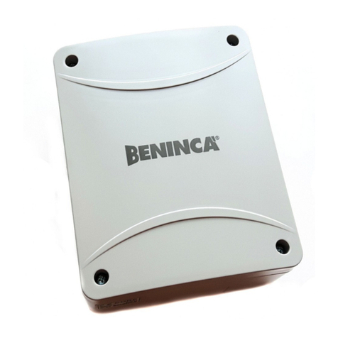
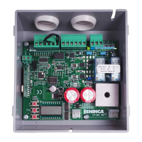
Beninca BRAINY 24 User manual

L8542589
05/2011 rev 0
BRAINY 24
UNIONE NAZIONALE COSTRUTTORI
AUTOMATISMI PER CANCELLI, PORTE
SERRANDE ED AFFINI

2
SHIELD
ANT
ANT
M1 M2
LAMP
24Vdc
SCA
PHOTO
TEST
II°CH/SERL
24Vac
Lock 12Vdc
10W (5s)
24Vac/dc
500mA max
(+) (-)
SWO1/ENC1
SWC1
SWO2/ENC2
SWC2
PHOT
PHOTC
STOP
OPEN
CLOSE
PED
P.P.
COM/ENC +
ENC -
COM/ENC+
F1
T 2A
DAS
J1 DAS
Open
DAS N.C.
J1 DAS
Close
DAS 8K2
2827
1 2 3 4 5 6 7 8 9 10 11 12 13 14 15 16 17 18 19 20 21 22 23 24 25 26
2827
8k2
DAS
32313029
+-
RADIO
U11
Code
____
F2:1.6AT (230V)
F2:3.2AT (115V)
L
N
1

3
SWO1/ENC1
SWO2/ENC2
ENC +
ENC -
F1
T 2A
DAS
2827
1 2 3 4 5 6 7 8 9 10 11 12 13 14 15 16 17 18 19 20 21 22 23 24 25 26
31303130
+-
RADIO
U11
M1
+ s -
M2
+ s -
3+3 x 0.5mm
2
max 10m
Collegamento ENCODER
ENCODER WIRING
2
3
4
24V ac 24V ac
COM
NC NO
RX1TX1
24V ac 24V ac
COM
NC NO
RX2TX2
11
24Vac
COM PHOT COM PHOT-C
24Vac
12 11 1213 18 13 199 10 9 10
test1:on test2:ON
SCA
AUX1:0 AUX1:2
SERVICE/ZONE LIGHT
Service Light
AUX1:3
Zone Light
L N
Service/Zone
Light
230Vac
Relè 24Vac
32313029
24Vac/dc
500mA max
11 12
32313029
24Vac/dc
500mA max
11 12

4
Dichiarazione CE di Conformità
Dichiarazione in accordo alle Direttive 2004/108/CE(EMC); 2006/95/CE(LVD)
Fabbricante:
Automatismi Benincà SpA
Indirizzo:
Via Capitello, 45 - 36066 Sandrigo (VI) - Italia
Dichiara che il prodotto:
Centrale di comando per 1 motore 24Vdc, per porte ad anta battente o scorrevole: BRAINY 24
è conforme alle condizioni delle seguenti Direttive CE:
• DIRETTIVA 2004/108/CE DEL PARLAMENTO EUROPEO E DEL CONSIGLIO del 15 dicembre 2004 concernente
il ravvicinamento delle legislazioni degli Stati membri relative alla compatibilità elettromagnetica e che abroga la direttiva
89/336/CEE, secondo le seguenti norme armonizzate:
EN 61000-6-2:2005, EN 61000-6-3:2007.
• DIRETTIVA 2006/95/CE DEL PARLAMENTO EUROPEO E DEL CONSIGLIO del 12 dicembre 2006 concernente il
ravvicinamento delle legislazioni degli Stati membri relative al materiale elettrico destinato ad essere adoperato entro taluni
limiti di tensione, secondo le seguenti norme armonizzate:
EN 60335-1:2002 + A1:2004 + A11:2004 + A12:2006 + A2:2006 + A13:2008; EN 60335-2-103:2003.
se applicabile:
• DIRETTIVA 1999/5/CE DEL PARLAMENTO EUROPEO E DEL CONSIGLIO del 9 marzo 1999 riguardante le ap-
parecchiature radio e le apparecchiature terminali di telecomunicazione e il reciproco riconoscimento della loro conformità,
secondo le seguenti norme armonizzate: ETSI EN 301 489-3 V1.4.1 (2002) + ETSI EN 301 489-1 V1.4.1 (2002) + ETSI EN
300 220-3 V1.1.1 (2000) + EN 60950-1 (2001)
Benincà Luigi, Responsabile legale.
Sandrigo, 02/11/2010.
AVVERTENZE
Questo manuale è destinato esclusivamente a personale
qualificato per l’installazione e la manutenzione di aperture
automatiche.
Nessuna informazione qui presente è di interesse o di utilità
per l’utente finale.
Conservare questo manuale per futuri utilizzi.
L’installatore deve fornire tutte le informazioni relative
al funzionamento automatico, manuale e di emergenza
dell'automazione, e consegnare all’utilizzatore dell’impian-
to le istruzioni d’uso.
•Prevedere sulla rete di alimentazione un interruttore/
sezionatore onnipolare con distanza d’apertura dei
contatti uguale o superiore a 3 mm.
Verificare che a monte dell’impianto elettrico vi sia un interrut-
tore differenziale e una protezione di sovracorrente adeguati.
Alcune tipologie di installazione richiedono il collegamento
dell'anta ad un impianto di messa a terra rispondente alle
vigenti norme di sicurezza.
L’installazione elettrica e la logica di funzionamento devono
essere in accordo con le normative vigenti.
I conduttori alimentati con tensioni diverse, devono essere
fisicamente separati, oppure devono essere adeguata-
mente isolati con isolamento supplementare di almeno
1 mm.
I conduttori devono essere vincolati da un fissaggio sup-
plementare in prossimità dei morsetti.
Durante gli interventi di installazione, manutenzione e ri-
parazione, togliere l’alimentazione prima di accedere alle
parti elettriche.
Ricontrollare tutti i collegamenti fatti prima di dare ten-
sione.
Gli ingressi N.C. non utilizzati devono essere ponticellati.
Le descrizioni e le illustrazioni presenti in questo manuale
non sono impegnative. Lasciando inalterate le caratte-
ristiche essenziali del prodotto il fabbricante si riserva il
diritto di apportare qualsiasi modifica di carattere tecnico,
costruttivo o commerciale senza impegnarsi ad aggiornare
la presente pubblicazione.

5
CENTRALE DI COMANDO BRAINY 24
FUNZIONE AUTOSET
IMPORTANTE: La centrale dispone della funzione Autoset per impostare automaticamente i principali valori di funzionamento a
seconda della tipologia di installaizione.
La funzione AUTOSET deve essere ripetuta ad ogni variazione dei parametri di funzionamento o al variare delle condizioni dell’au-
tomazione. Vedere il menu AUTO per ulteriori informazioni.
COLLEGAMENTI ELETTRICI
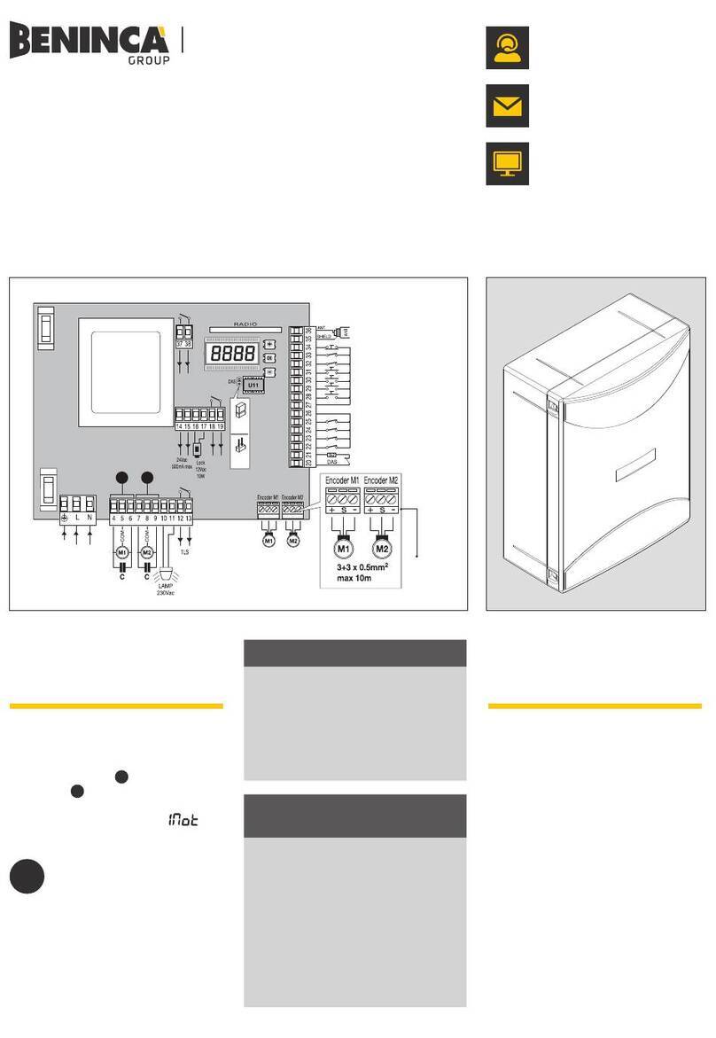
Nella seguente tabella sono descritti i collegamenti elettrici rappresentati in Fig. 1:
N° Morsetti Funzione Descrizione
1-2 Motore 1 Collegamento motore 1: 24Vdc 5 A max.
3-4 Motore 2 Collegamento motore 2: 24Vdc 5 A max.
5-6 Lampeggiante Collegamento lampeggiante 24Vdc 15W max.
7-8 Lock Uscita alimentazione 12Vdc/10W per elettroserratura (7:0V, 8:+12V).
9-10 SCA/
PHOTO TEST
Contatto libero da tensione N.O. configurabile come spia cancello aperto o test fotocel-
lule.
Per utilizzo come “Spia cancello aperto” le logiche TEST1 e TEST2 devono essere OFF
Per utilizzo come test fotocellule basta attivare una o entrambe le logiche TEST e collegare
le fotocellule come indicato in Fig.3.
11-12 24 Vac/dc
Uscita alimentazione accessori 24Vac/0,5A max.
ATTENZIONE: Nel caso di installazione della scheda caricabatteria, l’uscita (in assenza di
alimentazione di rete) presenta una tensione 24Vdc - polarizzata.
Verificare il corretto collegamento dei dispositivi (11:+24Vdc - 12:0Vdc).
13 COM/ENC+ Comune per finecorsa e tutti gli ingressi di comando o alimentazione encoder.
14 SWO1/ENC1 Ingresso finecorsa APRE motore 1 (contatto N.C.) o collegamento Encoder Motore 1.
15 SWC1 Ingresso finecorsa CHIUDE motore 1 (contatto N.C.).
16 SWO2/ENC2 Ingresso finecorsa APRE motore 2 (contatto N.C.) o collegamento Encoder Motore 2.
17 SWC2 Ingresso finecorsa CHIUDE motore 2 (contatto N.C.).
18 PHOT Ingresso fotocellula attiva in apertura e chiusura (contatto N.C.).
19 PHOT C Ingresso fotocellula attiva solo in chiusura (contatto N.C.).
20 STOP Ingresso pulsante STOP (contatto N.C.).
21 OPEN Ingresso pulsante APRE (contatto N.O.).
E’ possibile collegare un temporizzatore per aperture a fasce orarie.
22 CLOSE Ingresso pulsante CHIUDE (contatto N.O.).
23 PED Ingresso pulsante pedonale (contatto N.O.), comanda l’apertura del motore 1, vedi para-
metro TPED.
DATI TECNICI
Alimentazione centrale di comando 24Vdc
Alimentazione di rete 230 Vac 50/60 Hz oppure 115Vac 50/60Hz a seconda della versione
Uscita Motore 1/2 motore 24Vdc
Corrente massima motore 5+5 A
Uscita alimentazione accessori 24Vac/dc 500mA max.
Grado di protezione IP54
Temp. funzionamento -20°C / +70°C
Ricevitore radio 433,92 MHz incorporato e configurabile (rolling-code o fisso+rolling-code)
N° codici memorizzabili 64

6
24 Passo-Passo Ingresso pulsante passo-passo (contatto N.O.) .
25 COM/ENC+ Comune per finecorsa e tutti gli ingressi di comando o alimentazione encoder.
26 ENC- Ingresso per collegamento GND Encoder (vedi Fig.2).
27-28
BORDO
SENSIBILE
(DAS)
Ingresso contatto costa sensibile (contatto N.C.)
Costa resistiva: Jumper “DAS” chiuso
Costa meccanica: Jumper “DAS” aperto
L’intervento della costa arresta il movimento dell’anta e inverte per circa 3s.
29-30 II°CH/SERL
Contatto libero da tensione N.O. configurabile come secondo canale radio o luce di servizio.
Per utilizzo come secondo canale radio la logica 2CH deve essere ON.
Per utilizzo come luce di cortesia la logica 2CH deve essere OFF.
31-32 Antenna
Collegamento antenna scheda radioricevitore integrato (30-segnale/31-schermo).
+ / - 24Vac/dc
Ingresso alimentazione 24Vac/24Vdc.
Nel caso di utilizzo di batterie tampone collegare la scheda caricabatteria come indicato
nelle specifiche istruzioni di installazione.
U11 MEMORIA DI
CONFIGURAZIONE
Memoria Eprom estraibile. Contiene tutte le configurazioni della centrale (logiche, parametri,
ecc), inclusi i radiotrasmettitori. In caso di guasto è possibile estrarre la Eprom e inserirla in
una diversa centrale, evitando la riprogrammazione.
COLLEGAMENTO ENCODER
Nel caso il motore sia provvisto di Encoder e si desideri collegarlo alla centrale, effettuare i collegamenti indicati in Fig.2, in questo
caso gli ingressi SWO1 e SWO2 non possono essere utilizzati come ingressi finecorsa.
Non è possibile utilizzare contemporaneamente l’Encoder ed il finecorsa di chiusura.
Lasciare SWC1 e SWC2 ponticellati.
VERIFICA COLLEGAMENTI
1) Togliere alimentazione.
2) Sbloccare manualmente le ante, portarle a circa metà della corsa e ribloccarle.
3) Ripristinare l’alimentazione.
4) Dare un comando di passo-passo mediante pulsante <->.
5) Le ante devono muoversi in APERTURA.
Nel caso ciò non avvenisse, è sufficiente invertire tra loro i fili di marcia del motore. (1<>2 per il motore M1, e 3<>4 per il motore
M2) e, se utilizzati, i relativi ingressi di finecorsa (14<>15 per il motore M1, e 16<>17 per il motore M2).
PROGRAMMAZIONE
La programmazione delle varie funzionalità della centrale viene effettuata utilizzando il display LCD presente a bordo della centrale
ed impostando i valori desiderati nei menu di programmazione descritti di seguito.
Il menu parametri consente di impostare un valore numerico ad una funzione, in modo analogo ad un trimmer di regolazione.
Il menu logiche consente di attivare o disattivare una funzione, in modo analogo al settaggio di un dip-switch.
Altre funzioni speciali seguono i menu parametri e logiche e possono variare a seconda del tipo di centrale o revisione software.
PER ACCEDERE ALLA PROGRAMMAZIONE:
1 - Premere il pulsante <PG>, il display si porta nel primo menu Parametri “PAR”.
2 - Scegliere con il pulsante <+> o <-> il menu che si intende selezionare (PAR>LOG>RAD>NMAN>MACI>RES>AUTO>CODE).
3 - Premere il pulsante <PG>, il display mostra la prima funzione disponibile nel menu.
4 - Scegliere con il pulsante <+> o <-> la funzione che si intende modificare.
5 - Premere il pulsante <PG>, il display mostra il valore attualmente impostato per la funzione selezionata.
6 - Selezionare con il pulsante <+> o <-> il valore che si intende assegnare alla funzione.
7 - Premere il pulsante <PG>, il display mostra il segnale “PRG” che indica l’avvenuta programmazione.
NOTE:
La pressione simultanea di <+> e <-> effettuata all’interno di un menu funzione consente di tornare al menu superiore senza appor-
tare modifiche.
Mantenere la pressione sul tasto <+> o sul tasto <-> per accelerare l’incremento/decremento dei valori.
Dopo un’attesa di 120s la centrale esce dalla modalità programmazione e spegne il display.
La pressione del pulsante <-> a display spento equivale ad un comando passo-passo.
All’accensione della scheda viene visualizzata per circa 5s la versione software.
PARAMETRI, LOGICHE E FUNZIONI SPECIALI
Nelle tabelle di seguito vengono descritte le singole funzioni disponibili nella centrale.
PARAMETRI (PAR)
MENU FUNZIONE MIN-MAX-(Default) MEMO
TCA Tempo di chiusura automatica. Attivo solo con logica “TCA”=ON.
Al termine del tempo impostato la centrale comanda una manovra di chiusura. 1-240-(40s)

7
TM1
Tempo lavoro motore 1. Regola il tempo di funzionamento a velocità normale
durante la fase di apertura e chiusura del motore 1.
Vedi Paragrafo “Regolazioni velocità anta”
Impostando il valore a 0 la manovra viene eseguita con 2s circa di spunto e pro-
segue rallentata per tutta la corsa.
0-99-(5s)
TM2
Tempo lavoro motore 2. Regola il tempo di funzionamento a velocità normale
durante la fase di apertura e chiusura del motore 2.
Vedi Paragrafo “Regolazioni velocità anta”
Impostando il valore a 0 la manovra viene eseguita con 2s circa di spunto e pro-
segue rallentata per tutta la corsa.
0-99-(5s)
Tped
Regola la percentuale di apertura del motore 1 (funzione pedonale).
Con motori dotati di Encoder il valore è espresso in percentuale (99% apertura
completa dell’anta).
Con motori privi di Encoder o finecorsa elettrici, il valore è espresso in secondi.
1-99 (50%)
PMo1 Regola la soglia di intervento del dispositivo antischiacciamento* (sensore ampe-
rometrico) durante la fase di apertura a velocità normale - Motore 1 1-99-(50%)**
PMC1 Regola la soglia di intervento del dispositivo antischiacciamento* (sensore ampe-
rometrico) durante la fase di chiusura a velocità normale - Motore 1 1-99-(50%)**
PMo2 Regola la soglia di intervento del dispositivo antischiacciamento* (sensore ampe-
rometrico) durante la fase di apertura a velocità normale - Motore 2 1-99-(50%)**
PMc2 Regola la soglia di intervento del dispositivo antischiacciamento* (sensore ampe-
rometrico) durante la fase di chiusura a velocità normale - Motore 2 1-99-(50%)**
TDMo Tempo ritardo apertura Mot.2
Regola il tempo di ritardo in apertura del motore 2 rispetto al motore 1 0-15-(2s)
TDMC Tempo ritardo chiusura Mot.1
Regola il tempo di ritardo in chiusura del motore 1 rispetto al motore 2 0-40-(3s)
TLS
Tempo attivazione contatto SERL (Luce di servizio) morsetti 29/30.
Ad ogni manovra il contatto si chiude per il tempo impostato.
Vedere schema di collegamento Figura 4
1-240-(60s)
TLOc Tempo attivazione elettroserratura.
Valore espresso in 1/10s (0=0s - 50=5s)
0-50
(5=0,5s)
SLD1
Regola la velocità del motore 1 durante le fasi di rallentamento. Valore espresso in
percentuale rispetto alla velocità di normale funzionamento.
30-70 (40%)
SLD2
Regola la velocità del motore 2 durante le fasi di rallentamento. Valore espresso in
percentuale rispetto alla velocità di normale funzionamento.
30-70 (40%)
SpD1
Regola la velocità del motore 1 durante la fase di velocità normale.
Valore espresso in percentuale.
30-99 (99%)
SpD2
Regola la velocità del motore 2 durante la fase di velocità normale.
Valore espresso in percentuale.
30-99 (99%)
Pso1 Regola la soglia di intervento del dispositivo antischiacciamento* (sensore ampe-
rometrico) durante la fase di apertura a velocità rallentata - Motore 1 1-99-(20%)**
Psc1 Regola la soglia di intervento del dispositivo antischiacciamento* (sensore ampe-
rometrico) durante la fase di chiusura a velocità rallentata - Motore 1 1-99-(20%)**
Pso2 Regola la soglia di intervento del dispositivo antischiacciamento* (sensore ampe-
rometrico) durante la fase di apertura a velocità rallentata - Motore 2 1-99-(20%)**
Psc2 Regola la soglia di intervento del dispositivo antischiacciamento* (sensore ampe-
rometrico) durante la fase di chiusura a velocità rallentata - Motore 2 1-99-(20%)**
SeaU
Regola la soglia di intervento del dispositivo antischiacciamento (Encoder) durante
la fase a velocità normale*.
0:Off -1: minima sensibilità - 99: massima sensibilità
0-99-(0%)
SEAR
Regola la soglia di intervento del dispositivo antischiacciamento (Encoder) durante
la fase di rallentamento*.
0:Off -1: minima sensibilità - 99: massima sensibilità
0-99-(0%)
* ATTENZIONE: UN’ERRATA IMPOSTAZIONE DI QUESTI PARAMETRI PUÒ RISULTARE PERICOLOSA.
RISPETTARE LE NORMATIVE VIGENTI!
Con motori privi di finecorsa e/o encoder regola la sensibilità del sensore che provoca l’arresto durante la fase di rallen-
tamento.
** 1: minima forza/coppia - 99: massima forza/coppia

8
LOGICHE (LOG)
MENU FUNZIONE ON-OFF-(Default) MEMO
TCA
Abilita o disabilita la chiusura automatica
On: chiusura automatica abilitata
Off: chiusura automatica disabilitata
(ON)
IbL
Abilita o disabilita la funzione condominiale.
On: funzione condominiale abilitata. L’impulso P.P. o del trasmettitore non ha
effetto durante la fase di apertura.
Off: funzione condominiale disabilitata.
(OFF)
ibca
Abilita o disabilita la funzione condominiale.
On: funzione condominiale abilitata. L’impulso P.P. o del trasmettitore non ha
effetto durante il conteggio del TCA.
Off: funzione condominiale disabilitata.
(OFF)
SCL
Abilita o disabilita la chiusura rapida
On: chiusura rapida abilitata. Con cancello aperto o in fase di apertura l’intervento
della fotocellula provoca la chiusura automatica dopo 3 s dopo la completa
apertura. Attiva solo con TCA:ON
Off: chiusura rapida disabilitata.
(OFF)
PP
Seleziona la modalità di funzionamento del ”Pulsante P.P.” e del trasmettitore.
On: Funzionamento: APRE > CHIUDE > APRE >
Off: Funzionamento: APRE > STOP > CHIUDE > STOP >
(OFF)
PRE
Abilita o disabilita il pre-lampeggio.
On: Pre-lampeggio abilitato. Il lampeggiante si attiva 3s prima della partenza del
motore.
Off: Pre-lampeggio disabilitato.
(OFF)
HAM
Abilita o disabilita la funzione colpo di inversione
On: Funzione abilitata. Prima di ogni manovra di apertura o chiusura la centra-
le comanda una manovra di 2s in direzione opposta per facilitare lo sgancio
dell’elettroserratura.
Off: Funzione disabilitata.
(OFF)
Blco
Abilita o disabilita la funzione di blocco in apertura.
On: Funzione blocco abilitato. Da utilizzare solo con motori dotati di fine-
corsa. Dopo l’intervento dei finecorsa di apertura la centrale ritarda l’arresto
di circa 0,5s, in modo da consentire una migliore battuta dell’anta sui fermi di
arresto.
Off: Funzione blocco disabilitato.
(OFF)
Blcc
Abilita o disabilita la funzione di blocco in chiusura.
On: Funzione blocco abilitato. Da utilizzare solo con motori dotati di fine-
corsa. Dopo l’intervento dei finecorsa di chiusura la centrale ritarda l’arresto
di circa 0,5s, in modo da consentire una migliore battuta dell’anta sui fermi di
arresto.
Off: Funzione blocco disabilitato.
(OFF)
SOFT
Abilita o disabilita la partenza a velocità rallentata.
On: Esegue le partenze a velocità rallentata per 2 secondi per poi passare a
velocità normale.
Off: Partenza a velocità rallentata non attiva.
(OFF)
LTCA
Selezione la modalità di funzionamento del lampeggiante durante il tempo TCA
On: Lampeggiante acceso durante TCA
Off: Lampeggiante spento durante TCA
(OFF)
htr
Abilita o disabilita la funzione Uomo presente.
On: Funzionamento Uomo Presente.
La pressione dei pulsanti APRE/CHIUDE deve essere mantenuta durante tutta
la manovra. L’apertura dell’ingresso STOP arresta il motore. Tutti gli ingressi
di sicurezza sono disattivati, tranne gli ingressi finecorsa /SW01/SW02/SWC1/
SWC2).
Off: Funzionamento automatico/semiautomatico.
(OFF)
1mot
Seleziona la modalità di funzionamento 1/2 motori:
On: Attivo solo il motore 1.
Off: Entrambi i motori attivi.
(OFF)

9
Cvar
Abilita o disabilita i trasmettitori a codice programmabile.
On: Ricevitore radio abilitato esclusivamente ai trasmettitori a codice variabile
(rolling-code).
Off: Ricevitore abilitato a trasmettitori codice variabile (rolling-code) e program-
mabile (autoapprendimento e dip/switch) .
(OFF)
mloc
Seleziona il tipo di elettroserratura utilizzato.
On: Elettroserratura magnetica, normalmente alimentata a 12Vac/0,5Amax.
Prima di ogni manovra di apertura viene tolta alimentazione per il tempo impo-
stato dal parametro TLOC.
Off: Elettroserratura a scatto, normalmente non alimentata.
Prima di ogni manovra di apertura viene fornita alimentazione a 12Vac per il
tempo impostato dal parametro TLOC.
(OFF)
BB
Attiva o disattiva la funzione di spinta in chiusura. Solo con logica SLD:ON
On: L’ultimo secondo della manovra in fase di chiusura viene eseguito a velocità
normale (disabilitando il rallentamento) per favorire un migliore aggancio dell’elet-
troserratura.
Off: Funzione disabilitata.
(OFF)
2ch
Abilita o disabilita il secondo canale radio sui morsetti 29/30.
On: Uscita 29/30 configurata con funzionamento come secondo canale radio.
Off: Uscita 29/30 assume la funzione luce di servizio (vedi parametro TLS).
(OFF)
TST1
Abilita o disabilita la verifica delle fotocellule sull’ingresso PHOT, attivo sia in
chiusura, sia in apertura.
On: Verifica abilitata. Se la verifica ha esito negativo non viene comandata nes-
suna manovra. Vedi Fig.3 - “PHOTO TEST”.
Off: Verifica delle fotocellule ad ogni manovra disabilitata.
(OFF)
TST2
Abilita o disabilita la verifica delle fotocellule sull’ingresso PHOT, attivo solo in
chiusura.
On: Verifica abilitata. Se la verifica ha esito negativo non viene comandata nes-
suna manovra. Vedi Fig.3 - “PHOTO TEST”.
Off: Verifica delle fotocellule ad ogni manovra disabilitata.
(OFF)
TSTm
Abilita o disabilita la verifica motori.
On: Verifica abilitata. Se la verifica ha esito negativo non viene comandata nes-
suna manovra.
Off: Verifica disabilitata.
(OFF)
rem
Abilita o disabilita l’apprendimento remoto dei radiotrasmettitori, come indicato
nel paragrafo “Apprendimento remoto trasmettitori”.
On: Apprendimento remoto abilitato.
Off: Apprendimento remoto non abilitato.
(OFF)
RADIO (RAD)
MENU FUNZIONE
PP
Selezionando questa funzione la ricevente si pone in attesa (Push) di un codice trasmettitore da assegnare alla fun-
zione passo-passo.
Premere il tasto del trasmettitore che si intende assegnare a questa funzione.
Se il codice è valido, viene memorizzato e viene visualizzato il messaggio OK
Se il codice non è valido, viene visualizzato il messaggio Err.
2Ch
Selezionando questa funzione la ricevente si pone in attesa (Push) di un codice trasmettitore da assegnare al secondo
canale radio.
Premere il tasto del trasmettitore che si intende assegnare a questa funzione.
Se il codice è valido, viene memorizzato e viene visualizzato il messaggio OK
Se il codice non è valido, viene visualizzato il messaggio Err.
ped
Selezionando questa funzione la ricevente si pone in attesa (Push) di un codice trasmettitore da assegnare alla fun-
zione apertura pedonale (vedi parametro TPED).
Premere il tasto del trasmettitore che si intende assegnare a questa funzione.
Se il codice è valido, viene memorizzato e viene visualizzato il messaggio OK
Se il codice non è valido, viene visualizzato il messaggio Err.
CLR
Selezionando questa funzione la ricevente si pone in attesa (Push) di un codice trasmettitore da cancellare dalla
memoria.
Se il codice è valido, viene cancellato e viene visualizzato il messaggio OK
Se il codice non è valido o non è presente in memoria, viene visualizzato il messaggio Err
RTR
Cancella completamente la memoria della ricevente. Viene richiesta conferma dell’operazione.
Selezionando questa funzione la ricevente si pone in attesa (Push) di un una nuova pressione di PGM a conferma
dell’operazione.
A fine cancellazione viene visualizzato il messaggio OK

10
NUMERO MANOVRE (Nman)
Visualizza il numero di cicli completi (apre+chiude) effettuate dall’automazione. La prima pressione del pulsante <PG>, visualizza
le prime 4 cifre, la seconda pressione le ultime 4. Es. <PG> 0012 >>> <PG> 3456: effettuati 123.456 cicli.
CICLI MANUTENZIONE (maci)
Questa funzione consente di attivare la segnalazione di richiesta manutenzione dopo un numero di manovre stabilito dall’instal-
latore. Per attivare e selezionare il numero di manovre, procedere come segue:
Premere il pulsante <PG>, il display viusalizza OFF, che indica che la funzione è disabilitata (valore di default).
Con i pulsanti <+> e <-> selezionare uno dei valori numerici proposti (da OFF a 100). I valori vanno intesi come centinaia di cicli
di manovre (ad es.: il valore 50 sta ad indicare 5000 manovre).
Premere il pulsante OK per attivare la funzione. Il display visualizza il messaggio PROG.
La richiesta di manutenzione viene segnalata all’utente con il lampeggio dei LED della luce di cortesia durante la manovra di
apertura e chiusura.
RESET (RES)
RESET della centrale. ATTENZIONE!: Riporta la centrale ai valori di default.
La prima pressione del pulsante <PG> provoca il lampeggio della scritta RES, una ulteriore pressione del pulsante <PG> effettua
il reset della centrale. Nota: Non vengono cancellati i trasmettitori dalla ricevente ne la password di accesso.
Vengono riportati ai valori di default tutte le logiche e tutti i parametri, è pertanto necessario ripetere la procedura di autoset.
AUTOSET (AUTO)
Questa funzione va utilzzata per settare i valori ottimali di funzionamento dell’automazione, e al termine della procedura, setta dei
valori medi di COPPIA, TEMPO LAVORO e RALLENTAMENTO.
Per effettuare l’autoset, procedere come segue:
a) Accertarsi che nell’area di manovra delle ante non siano presenti ostacoli di nessuna natura, se necessario, transennare l’area
in modo da impedire l’accesso a persone, animali, auto, ecc.
Durante la fase di autoset, la funzione di antischiacciamento non è attiva.
b) Selezionare la funzione AUTO e premere OK.
c) Selezionare con il pulsante <+> o <-> il sotto-menu NOLS, LSW o ENC a seconda della presenza di finecorsa e/o encoder:
NOLS: se il motore è privo di finecorsa e di encoder
LSW: se il motore è provvisto di fincorsa e privo di encoder
ENC: se il motore è provvisto di encoder e privo di finecorsa
d) selezionato la voce premere OK per dare inizio alla fase di autoset.
La centrale esegue una serie di manovre per l’apprendimento della corsa delle ante e per la configurazione dei parametri.
Inizialmente entrambe le ante vengono portate in posizione di apertura, quindi dopo alcune manovre di apertura e chiusura a di-
verse velocità, di una o di entrambe le ante, la centrale visualizza il messaggio OK. Nel caso l’operazione non abbia esito positivo
viene visualizzato il messaggio ERR. Ripetere l’operazione dopo aver ricontrollato i cablaggi e l’eventuale presenza di ostacoli.
Nel caso vengano modificati i parametri TM1/TM2 o la velocità ripetere la procedura di autoset.
Durante le manvore il display visualizza alcune sigle: OPM1/OPM2 durante l’apertura del motore 1 o 2 e CLM1/CLM2 durante la
chiusura del motore 1 o 2.
PASSWORD DI ACCESSO (CODE)
Consente di inserire un codice di protezione di accesso alla programmazione della centrale.
E’ possibile inserire un codice alfanumerico di quattro caratteri utilizzando i numeri da 0 a 9 e le lettere A-B-C-D-E-F.
Il valore di default è 0000 (quattro zeri) e indica l’assenza di codice di protezione.
In qualsiasi momento è possibile annullare l’operazione di inserimento del codice, premendo contemporaneamente i tasti + e -.
Una volta inserita la password è possibile operare sulla centrale, entrando ed uscendo dalla programmazione per un tempo di
circa 10 minuti, in modo da consentire le operazioni di regolazione e test delle funzioni.
Sostituendo il codice 0000 con qualsiasi altro codice si abilita la protezione della centrale, impedendo l’accesso a tutti i menu.
Se si desidera inserire un codice di protezione, procedere come segue:
- selezionare il menu Code e premere OK.
- viene visualizzato il codice 0000, anche nel caso sia già stato inserito in precedenza un codice di protezione.
- con i tasti + e - si può variare il valore del carattere lampeggiante.
- con il tasto OK si conferma il carattere lampeggiante e si passa al successivo.
- dopo aver inserito i 4 caratteri compera un messaggio di conferma “CONF”.
- dopo alcuni secondi viene ri-visualizzato il codice 0000
- è necessario riconfermare il codice di protezione precedentemente inserito, in modo da evitare inserimenti involontari.
Se il codice corrisponde al precedente, viene visualizzato un messaggio di conferma “OK”
La centrale esce automaticamente dalla fase di programmazione, e per accedere nuovamente ai menu sarà necessario inserire
il codice di protezione memorizzato.
IMPORTANTE: ANNOTARE il codice di protezione e CONSERVARLO IN LUOGO SICURO per future manutenzioni. Per
rimuovere un codice da una centrale protetta è necessario entrare in programmazione con la password e riportare il
codice al valore di default 0000.
IN CASO DI SMARRIMENTO DEL CODICE È NECESSARIO RIVOLGERSI ALL’ASSISTENZA
TECNICA AUTORIZZATA, PER IL RESET TOTALE DELLA CENTRALE.
11
APPRENDIMENTO REMOTO TRASMETTITORI
Se si dispone di un trasmettitore già memorizzato nella ricevente è possibile effettuare l’apprendimento radio remoto (senza neces-
sità di accedere alla centrale).
IMPORTANTE: La procedura deve essere eseguita con ante in apertura durante la pausa TCA o a cancello aperto se la lo-
gica TCA è OFF. La logica REM deve essere ON.
Procedere come segue:
1 Premere il tasto nascosto del trasmettitore già memorizzato.
2 Premere, entro 5s, il tasto del trasmettitore già memorizzato corrispondente al canale da associare al nuovo trasmettitore. Il lam-
peggiante si accende.
3 Premere entro 10s il tasto nascosto del nuovo trasmettitore.
4 Premere, entro 5s, il tasto del nuovo trasmettitore da associare al canale scelto al punto 2. Il lampeggiante si spegne.
5 La ricevente memorizza il nuovo trasmettitore ed esce immediatamente dalla programmazione.
FUSIBILI
F1: Fusibile di protezione alimentazione accessori.
F2: Fusibile di protezione generale
BATTERIA DI EMERGENZA
E’ disponibile un accessorio opzionale per l’alimentazione della centrale in caso di assenza di alimentazione di rete.
Il kit è composto da una scheda caricabatteria e da due batterie da 12V ricaricabili, staffe di fissaggio, viti e cablaggi.
Per utlteriori informazioni fate riferimento alle istruzioni fornite con l’accessorio.
DIAGNOSTICA
PHOT
SWC1
STOP
SWO1 SWO2
SWC2
PHOT-C DAS
P.P. PED OPEN CLOSE
Ad ogni ingresso è associato un segmento del display che in caso di attivazione si ac-
cende, secondo il seguente schema.
Gli ingressi N.C. sono rappresentati dai segmenti verticali.
Gli ingressi N.O. sono rappresentati dai segmenti orizzontali.
La centrale visualizza il messaggio AMP1 o AMP2 in caso di intervento del sensore am-
perometrico antischiacciamento.
MESSAGGI DI ERRORE
Di seguito sono elencati alcuni messaggi che vengono visualizzati dal display in caso di anomalie di funzionamento:
Amp1 errore ostacolo motore 1/antischiacciamento verificare presenza di ostacoli sulla corsa dell’anta motore 1
Amp2 errore ostacolo motore 2/antischiacciamento verificare presenza di ostacoli sulla corsa dell’anta motore 2
Err1 errore verifica circuito motore 1 verificare collegamenti motore 1
Err2 errore verifica circuito motore 2 verificare collegamenti motore 2
Err3 errore/guasto circuito di potenza richiedere assistenza tecnica eventualmente sostituire la centrale.
Err4 errore verifica fotocellula PHOTA verificare collegamenti, allineamento fotocellula PHOT A o presenza
ostacoli.
Err5 errore verifica fotocellula PHOTC verificare collegamenti, allineamento fotocellula PHOT C o presenza
ostacoli.
Err6 errore costa attiva (durante autoset) in fase di autoset è intervenuta la costa di sicurezza.
Err7 errore stop attivo (durante autoset) in fase di autoset è intervenuto l’ingresso STOP.
Err8 errore ingresso attivo (durante autoset) in fase di autoset è intervenuto un ingresso PP/Open/Close.
thrm intervento protezione termica motore attendere il raffreddamento del motore, nel caso non avvenga il ripristino,
può essere necessaria la sostituzione del motore
SMALTIMENTO
Qualora il prodotto venga posto fuori servizio, è necessario seguire le disposizioni legislative in vigore al momento per quanto riguarda
lo smaltimento differenziato ed il riciclaggio dei vari componenti (metalli, plastiche, cavi elettrici, ecc.); è consigliabile contattare il
vostro installatore o una ditta specializzata ed abilitata allo scopo.

12
EC Declaration of conformity
Declaration pursuant to Directives 2004/108/EC(EMC); 2006/95/EC(LVD)
Manufacturer:
Automatismi Benincà SpA
Address:
Via Capitello, 45 - 36066 Sandrigo (VI) - Italy
Declares that the product:
Command central for 1 24Vdc motor, for single or sliding doors: BRAINY 24
is compliant with the conditions of the following EC Directives:
• DIRECTIVE 2004/108/EC OF THE EUROPEAN PARLIAMENT AND COUNCIL of December 15 2004 regarding
the approximation of the legislations of the member States relative to electromagnetic compatibility and that repeals directive
89/336/CEE, according to the following concurred norms:
EN 61000-6-2:2005, EN 61000-6-3:2007.
• DIRECTIVE 2006/95/EC OF THE EUROPEAN PARLIAMENT AND THE COUNCIL of December 12 2006 concer-
ning the approximation of the legislations of the member States relative to electrical material destined to be used within certain
voltage limits, according to the following concurred regulations:
EN 60335-1:2002 + A1:2004 + A11:2004 + A12:2006 + A2:2006 + A13:2008; EN 60335-2-103:2003.
if applicable :
• DIRECTIVE 1999/5/EC OF THE EUROPEAN PARLIAMENT AND THE COUNCIL of March 9 1999 regarding radio
devices and terminal and telecommunications devices and the reciprocal recognisances of their conformity, according to the
following concurred regulations: ETSI EN 301 489-3 V1.4.1 (2002) + ETSI EN 301 489-1 V1.4.1 (2002) + ETSI EN 300 220-3
V1.1.1 (2000) + EN 60950-1 (2001)
Benincà Luigi, Legal manager.
Sandrigo, 02/11/2010.
WARNINGS
This manual has been especially written to be use by
qualified fitters.
None of the information provide in this manual can be
considered as being of interest for the end users.
Preserve this manual for future needs.
The technician has to furnish all the information related to
the step by step function, the manual and the emergency
function of the operator, and to deliver the manual to the
final user.
•Foresee on the supply net an onnipolar switch or
selector with distance of the contacts equal or
superior to 3 mms.
Verify that of the electrical system there is an awry diffe-
rential interrupter and overcurrent protection.
Some typologies of installation require the connection of
the shutter to be link at a conductive mass of the ground
according to the regulations in force.
The electrical installation and the operating logic must
comply with the regulations in force.
The leads fed with different voltages must be physically
separate, or they must be suitably insulated with additional
insulation of at least 1 mm.
The leads must be secured with an additional fixture near
the terminals.
During installation, maintenance and repair, interrupt the
power supply before opening the lid to access the elec-
trical parts
Check all the connections again before switching on the
power.
The unused N.C. inputs must be bridged.
The descriptions and the present illustrations in this manual
are not binding. Leaving the essential characteristics of the
product unchanged, the manufacturer reserves himself
the right to bring any change of technical, constructive
or commercial character without undertaking himself to
update the present publication.

13
TECHNICAL DATA
Contol unit supply 24 Vdc
Power supply 230 Vac 50/60 Hz or 115Vac 50/60Hz according to the version
Output supply 1/2 motor 24Vdc
Maximum motor current 5+5 A
Output supply accessories 24Vdc 500mA max.
Protection level IP54
Operating temp. -20°C / +70°C
Radio receiver
built in 433,92 MHz confgurabile (rolling-code or programmable + rolling-code)
Rolling code transmitters supported 64
BRAINY 24 CONTROL UNIT
AUTOSET FUNCTION
IMPORTANT: The control unit is equipped with the Autoset function to automatically set the main functioning values based on the
type of installation.
The AUTOSET function must be repeated at every function parameter change or upon change of automation conditions. See the
AUTO menu for further information.
WIRE DIAGRAM
Wire connections shown in Fig. 1 are described hereunder:
Terminal
No. Function Description
1-2 Motor 1 Connection, motor 1: 24VDC 5A max
3-4 Motor 2 Connection, motor 2: 24VDC 5A max
5-6 Flashing light Connection, flashing light 24VDC 15W max.
7-8 Lock Output, 12Vdc/10W power supply for electric lock (7:0V, 8:+12V)
9-10 SCA/
PHOTO TEST
Contact free from N.O. Voltage, may be configured as open gate indicator or photocell
test.
For use as “Open gate indicator” the TEST1 and TEST2 logics must be OFF
For use as photocell test it is sufficient to activate one or both TEST logics and connect the
photocells as indicated in Fig.3.
11-12 24 Vac/dc
Output, accessory power supply, 24VAC/0.5A max.
IMPORTANT: If the battery charger board is installed, the output (without mains power con-
nected) has a 24Vdc polarised voltage.
Make sure the devices are correctly connected (i.e. 11:+24Vdc / 12:-0Vdc).
13 COM/ENC+ Common for limit switch and all the command inlets or encoder power supply.
14 SWO1/ENC1 Motor 1 OPEN limit switch input (N.C. contact) or Motor 1 Encoder connection.
15 SWC1 Motor 1 CLOSE limit switch input, (N.C. Contact)
16 SWO2/ENC2 Motor 2 OPEN limit switch input, (N.C. Contact) or Motor 2 Encoder connection.
17 SWC2 Motor 2 CLOSE limit switch input, (N.C. Contact)
18 PHOT Input, photocell activated in both opening and closing phases
19 PHOT C Input, photocell activated in closing phase only (Normally closed contact)
20 STOP Input, STOP push-button (Normally closed contact)
21 OPEN Input, OPEN push-button (Normally open contact).
It is possible to connect a timer for opening in time slots.
22 CLOSE Input, CLOSE push-button (Normally open contact)
23 PED Pedestrian button input (N.O. Contact), controls the motor 1 opening, see TPED param-
eter.
24 Step-by-Step Input, step-by-step push button (Normally open contact)
25 COM/ENC+ Common for Limit switch and all the command inputs or encoder power supply.

14
26 ENC- Input for GND Encoder connection (see Fig.2).
27-28
SENSITIVE
EDGE
(DAS)
Input, sensitive edge contact
Resistive edge: “DAS” Jumper closed
Mechanical edge: “DAS” Jumper open
When the edge is activated, the gate movement is stopped and reversed for about 3s.
29-30 II°CH/SERL
N.O. Contact free from Voltage, may be configured as second radio channel or service light.
For use as second radio channel the 2CH logic must be ON.
For use as courtesy light the 2CH logic must be OFF.
31-32 Antenna Connection to the built-in radio receiver card (30-signal/31-screen).
+ / - 24VAC/dc
Input, 24VAC/24VDC power supply.
In case of use of plug batteries connect the battery charging card as indicated in the specific
installation instructions.
U11 CONFIGURATION
MEMORY
Extractable Eprom Memory. Contains all the control unit configurations (logics, parameters,
etc.), including the radiotransmitters. In case of faults it is possible to extract Eprom and
insert it into a different control unit, avoiding reprogramming.
ENCODER WIRING
In case the motor is with Encoder and one wished to connect it to the control unit, carry out the connections indicated in Fig.2, in
this case the SWO1 and SWO2 inputs may not be used as Limit switch inputs.
It is not possible to use the Encoder and the closure Limit switch simultaneously.
Leave SWC1 and SWC2 shorted.
TO CHECK CONNECTIONS
1) Cut-off power supply.
2) Manually release the wings, move them to approx. half-stroke and lock them again.
3) Reset power supply.
4) Send a step-by-step control signal by pressing the <-> push-button.
5) The leeaves must move in OPENING.
In case this does not happen, it is sufficient to invert among them the motor run wires. (1<>2 for M1 motor, and 3<>4 for M2
motor) and, if used, the relative Limit switch inputs (14<>15 for M1 motor, and 16<>17 for M2 motor).
PROGRAMMING
The programming of the various functions of the control unit is carried out using the LCD display on the control unit and setting the
desired values in the programming menus described below.
The parameters menu allows you to assign a numerical value to a function, in the same way as a regulating trimmer.
The logic menu allows you to activate or deactivate a function, in the same way as setting a dip-switch.
Other special functions follow the parameters and logic menus and may vary depending on the type of control unit or the software
release.
TO ACCESS PROGRAMMING:
1 – Press the button <PG>, the display goes to the first menu, Parameters “PAR”.
2 – With the <+> or <-> button, select the menu you want (PAR>LOG>RAD>NMAN>MACI>RES>AUTO>CODE).
3- Press the button <PG>, the display shows the first function available on the menu.
4 - With the <+> or <-> button, select the function you want.
5 - Press the button <PG>, the display shows the value currently set for the function selected.
6 - With the <+> or <-> button, select the value you intend to assign to the function.
7 - Press the button <PG>, the display shows the signal “PRG” which indicates that programming has been completed.
NOTES:
Simultaneously pressing <+> and <-> from inside a function menu allows you to return to the previous menu without making any
changes. Hold down the <+> key or the <-> key to accelerate the increase/decrease of the values.
After waiting 120s the control unit quits programming mode and switches off the display.
When the board is switched on, the software version is displayed for around 5 sec
Hold down the <+> key or the <-> key to accelerate the increase/decrease of the values.
PARAMETERS, LOGIC AND SPECIAL FUNCTIONS
The tables below describe the individual functions available in the control unit.
PARAMETERS (PAR)
MENU FUNCTION MIN-MAX-(Default) MEMO
TCA Automatic closing time. Active only with logic “TCA”=ON.
At the end of the set time the control unit orders a closing manoeuvre. 1-240-(40s)

15
TM1
Operating time, motor 1. The operating time is adjusted at normal speed during
motor 1 opening and closing phases. See Paragraph “Adjustment of the gate
leaf speed”.
By setting the value to 0, the operation is performed with around 2 seconds of
pick-up and then the movement is carried on at reduced speed for the entire
stroke.
0-99-(5s)
TM2
Operating time, motor 2. The operating time is adjusted at normal speed during
motor 2 opening and closing phases. See Paragraph “Adjustment of the gate
leaf speed”.
By setting the value to 0, the operation is performed with around 2 seconds of
pick-up and then the movement is carried on at reduced speed for the entire
stroke.
0-99-(5s)
Tped
Adjusts the motor 1 opening percentage (pedestrian function).
With Encoder equipped motors the value is expressed in a percentage (99% mean
complete opening cycle).
With the motors without Encoder or electrical Limit switch, the value is expressed
in seconds.
1-99 (50%)
PMo1 The anti-crash device* (amperometric sensor) operation is adjusted in the open-
ing phase, at normal speed - Motor 1. 1-99-(50%)**
PMC1 The anti-crash device* (amperometric sensor) operation is adjusted in the closing
phase, at normal speed - Motor 1. 1-99-(50%)**
PMo2 The anti-crash device* (amperometric sensor) operation is adjusted in the open-
ing phase, at normal speed - Motor 2. 1-99-(50%)**
PMc2 The anti-crash device* (amperometric sensor) operation is adjusted in the closing
phase, at normal speed - Motor 2. 1-99-(50%)**
TDMo Mot.2 opening delay time.
Regulates the delay time of motor 2 on opening with respect to motor 1 0-15-(2s)
TDMC Mot.1 closing delay time
Regulates the delay time of motor 1 on closing with respect to motor 2 0-40-(3s)
TLS
SERL contact activation time (Service light) 29/30 terminals.
At each manoeuvre the contact closes for the set time.
See Figure 4 connection scheme.
1-240-(60s)
TLOc Electric lock activation time. The value is expressed in 1/10s (0=0s - 50=5s) 0-50 (5=0,5s)
SLD1 Adjusts motor 1 speed during slowing phases. Value expressed in percentage of
normal functioning speed. 30-70 (40%)
SLD2 Adjusts motor 2 speed during slowing phases. Value expressed in percentage of
normal functioning speed. 30-70 (40%)
SpD1 Adjusts motor 1 speed during normal speed phase.
Value expressed in percentage. 30-99 (99%)
SpD2 Adjusts motor 2 speed during normal speed phase.
Value expressed in percentage. 30-99 (99%)
Pso1 The anti-crash device* (amperometric sensor) operation is adjusted in the open-
ing phase, at reduced speed - Motor 1. 1-99-(20%)**
Psc1 The anti-crash device* (amperometric sensor) operation is adjusted in the closing
phase, at reduced speed - Motor 1. 1-99-(20%)**
Pso2 The anti-crash device* (amperometric sensor) operation is adjusted in the open-
ing phase, at reduced speed - Motor 2. 1-99-(20%)**
Psc2 The anti-crash device* (amperometric sensor) operation is adjusted in the closing
phase, at reduced speed - Motor 2. 1-99-(20%)**
SeaU
The intervention threshold of the anti-crashing device (Encoder) during the phase
at normal speed is adjusted.*
0:Off-1:minimum sensitivity - 99: maximum sensitivity
0-99-(0%)
SEAR
The intervention threshold of the anti-crashing device (Encoder) during braking
is adjusted *.
0:Off-1:minimum sensitivity - 99: maximum sensitivity
0-99-(0%)
* WARNING: AN INCORRECT SETTING OF THESE PARAMETERS MAY RESULT IN AN HAZARD.
COMPLY WITH REGULATIONS IN FORCE!
With motors without limit switch and/or encoder it adjusts the sensitivity of the sensor which causes arrest during
slowing phase.
** 1: minimum force/torque - 99: maximum force/torque

16
LOGIC (LOG)
MENU FUNCTION ON-OFF-(Default) MEMO
TCA
Enables or disables automatic closing
On: automatic closing enabled
Off: automatic closing disabled
(ON)
IbL
Enables or disables condominium function.
On: condominium function enabled. The step-by-step impulse or transmitter
impulse has no effect during the opening phase.
Off: condominium function disabled.
(OFF)
ibca
The bloc of flat function is enabled or disabled.
On: the bloc of flat function is enabled. The Step-by-Step signal or the transmitter
signal has no effect during the TCA counting.
Off: the bloc of flat function is disabled.
(OFF)
SCL
Enables or disables rapid closing
On: rapid closure is enabled. With open gate, or in the opening phase, the
activation of the photocell causes the automatic closure 3sec after the total
opening of the gate. It is activated only with TCA:ON
Off: rapid closing disabled.
(OFF)
PP
Selects the operating mode of the ”Step by step button” and of the transmitter.
On: Operation: OPEN > CLOSE > OPEN >
Off: Operation: OPEN > STOP > CLOSE > STOP >
(OFF)
PRE
Enables or disables pre-blinking.
On: Pre-blinking enabled. Blinking is activated 3s before the motor starts.
Off: Pre-blinking disabled.
(OFF)
HAM
Enables or disables the inversion stroke function
On: Function enabled. Before each opening or closing manoeuvre the control
unit orders a manoeuvre of 2s in the opposite direction to facilitate the release
of the electric lock.
Off: Function disabled.
(OFF)
Blco
Enables or disables the block function in opening.
On: Block function enabled. To use only with motors equipped with Limit
switch. After the intervention of the opening Limit switch the control unit delays
arrest by about 0.5s, so to allow a better strike of the shutter on the stop locks.
Off: Block function disabled
(OFF)
Blcc
Enables or disables the block function in closing.
On: Block function enabled. To use only with motors equipped with Limit
switch. After the intervention of the opening Limit switch the control unit delays
arrest by about 0.5s, so to allow a better strike of the shutter on the stop locks.
Off: Block function disabled.
(OFF)
SOFT
Enables or disables start at decreased speed.
On: Executes start ups at decreased speed for 2 seconds to then shift to normal
speed.
Off: Start at decreased speed not active.
(OFF)
LTCA
Selects the operating mode of the blinking light during the time TCA
On: Blinking light on during TCA
Off: Blinking light off during TCA
(OFF)
htr
Enabled or disables HOLD-TO-RUN function
On: HOLD-TO-RUN function.
The pressure of the OPENS/CLOSES button must be maintained throughout the
entire manoeuvre. The opening of the STOP input stops the motor. All the safety
inputs are deactivated, except for the Limit switch inputs /SW01/SW02/SWC1/
SWC2).
Off: Automatic/semiautomatic function
(OFF)
1mot
Select the 1/2 motors operating mode:
On: Only motor 1 operating.
Off: Both motors operating.
(OFF)
Cvar
The code programmable transmitters is enabled or disabled.
On: Radio receiver enabled only for rolling-code transmitters.
Off: Receiver enabled for rolling-code and programmable code transmitters
(self-learning and Dip Switch).
(OFF)

17
mloc
Selects the type of electric lock used.
On: Magnetic electric lock, normally fed at 12Vdc.
Before each opening manoeuvre the power supply is interrupted for the time set
by the parameter TLOC.
Off: Electric lock with latch, normally not fed.
Before each opening manoeuvre power is fed at 12Vdc for the time set by the
parameter TLOC.
(OFF)
BB
Activates or deactivates the push in closing function. Only with logic SLD:ON
On: The last second of the manoeuvre in closing phase is carried out at normal
speed (disabling slowing) to favour a better hook of the electric lock.
Off: Function disabled.
(OFF)
2ch
Enables or disables the second radio channel on terminals 29/30.
On: Exit 29/30 configured with function as second radio channel.
Off: Exit 29/30 takes on function of service light (see parameter TLS).
(OFF)
TST1
Enables or disables checking of photocells on PHOT input, active both in closing
and in opening.
On: Check enabled. If the check has a negative result, no manoeuvre is com-
manded. See Fig.3 - “PHOTO TEST”.
Off: Checking of photocells disabled at each manoeuvre.
(OFF)
TST2
Enables or disables checking of photocells on PHOT inputs, active only in clos-
ing.
On: Check enabled. If the check has a negative result, no manoeuvre is com-
manded. See Fig.3 - “PHOTO TEST”.
Off: Checking of photocells disabled at each manoeuvre.
(OFF)
TSTm
Enables or disables motors check.
On: Check enabled. If the check has a negative result, no manoeuvre is com-
manded.
Off: Check disabled.
(OFF)
rem
(Enables or disables remote radiotransmitters learning, as indicated in the para-
graph “Remote transmitters learning”.
On: Remote learning enabled.
Off: Remote learning not enabled.
(OFF)
RADIO (RAD)
MENU FUNZIONE
PP
By selecting this function, the receiver goes in waiting (Push) for a transmitter code to assign to the step-step func-
tion.
Press the key of the transmitter to assign to this function.
If the code is valid, it is memorised and the message OK is displayed
If the code is not valid, the message Err is displayed
2Ch
By selecting this function, the receiver goes into waiting (Push) for a transmitter code to assign to the second radio
channel.
Press the key of the transmitter to assign to this function.
If the code is valid, it is memorised ad the OK message is displayed
If the code is not valid, the message Err is displayed.
ped
By selecting this function, the receiver goes into waiting (Push) for a transmitter code to assign to the pedestrian
opening function (see parameter TPED).
Press the key of the transmitter to assign to this function.
If the code is valid, it is memorised ad the OK message is displayed
If the code is not valid, the message Err is displayed.
CLR
By selecting this function, the receiver goes into waiting (Push) for a transmitter code to erase from the memory.
If the code is valid, it is erased and the message OK is displayed
If the code is not valid or not present in memory, the message Err is displayed
RTR
Completely erases memory of the receiver. Confirmation of the operation is requested.
By selecting this function the receiver goes into waiting (Push) for a new PGM pressure to confirm the operation.
At end of erasing the OK message is displayed
CYCLES NUMBER (Nman)
Displays the number of complete cycles (open+close) carried out by the automation.
When the <PG> button is pressed for the first time, it displays the first 4 figures, the second time it shows the last 4. Example
<PG> 0012 >>> <PG> 3456: made 123.456 cycles.

18
MAINTENANCE CYCLES (maci)
This function enables to activate the maintenance request notice after a number of manoeuvres determined by the installer.
To activate and select the number of manoeuvres, proceed as follows:
Press button <PG>, the display will show OFF, which indicated that the function is disabled (default value).
With the buttons <+> and <-> select one of the numeric values proposed (from OFF to 100). The values are intended as hundreds
of cycles of manoeuvres (for example: the value 50 indicates 5000 manoeuvres).
Press the OK button to activate the function. The display will show the message PROG.
The maintenance request is noted to the user through flashing of the LEDs of the courtesy light during opening and closing ma-
noeuvre.
RESET (RES)
RESET of the control unit. ATTENTION!: Returns the control unit to the default values.
Pressing the <PG> button for the first time causes blinking of the letters RES, pressing the <PG> button again resets the control
unit. Note: The transmitters are not erased from the receiver nor is the access password.
All the logics and all the parameters are brought back to default values, it is therefore necessary to repeat the autoset proce-
dure.
AUTOSET (AUTO)
This function must be used to set the optimal automation function values, and at the end of the procedure, it sets medium values
of TORQUE, WORK TIME and SLOWING.
To carry out autoset, proceed as follows:
a) Ascertain that no obstacles of any nature are present in the manoeuvre area, if necessary, block off the area in order to prevent
access from people, animals, vehicles, etc.
During autoset phase, the anti-crushing function is not active.
b) Select the AUTO function and press OK.
c) Select with the <+> or <-> button the submenu, NOLS, LSW or ENC based on the presence of Limit switch and/or encoder:
NOLS: if the motor is without Limit switch and encoder
LSW: if the motor is equipped with Limit switch and without encoder
ENC: if the motor is equipped with encoder and without Limit switch
d) once selected press OK to begin the autoset phase.
The control unit carries out a series of manoeuvres for learning of the run of the leves and for parameter configuration.
Initially both the leaves are brought to opening position, then after some opening and closing manoeuvres at different speeds, of
one or both the shutters, the control unit displays the message OK. In case the operation has no positive result, the message ERR
is displayed. Repeat the operation after re-checking the wiring and the eventual presence of obstacles.
In case parametersTM1/TM2 or the speed are changed, repeat the autoset procedure.
During the manoeuvres the display will show some abbreviations: OPM1/OPM2 during opening of the motor 1 or 2 and CLM1/
CLM2 during closing of motor 1 or 2.
PROTECTION CODE (CODE)
It allows to type in an access protection code to the programming of the control unit.
A four-character alphanumeric code can be typed in by using the numbers from 0 to 9 and the letters A-B-C-D-E-F.
The default value is 0000 (four zeros) and shows the absence of a protection code.
While typing in the code, this operation can be cancelled at any moment by pressing keys + and – simultaneously. Once the
password is typed in, it is possible to act on the control unit by entering and exiting the programming mode for around 10 minutes
in order to allow adjustments and tests on functions.
By replacing the 0000 code with any other code, the protection of the control unit is enabled, thus preventing the access to any
other menu. If a protection code is to be typed in, proceed as follows:
- select the Code menu and press OK.
- the code 0000 is shown, also in the case a protection code has been previously typed in.
- the value of the flashing character can be changed with keys + and -.
- press OK to confirm the flashing character, then confirm the following one.
- after typing in the 4 characters, a confirmation message “CONF” appears.
- after a few seconds, the code 0000 appears again
- the previously stored protection code must be reconfirmed in order to avoid any accidental typing in.
If the code corresponds to the previous one, a confirmation message “OK” appears.
The control unit automatically exits the programming phase. To gain access to the Menus again, the stored protection code must
be typed in.
IMPORTANT: TAKE NOTE of the protection code and KEEP IT IN A SAFE PLACE for future maintenance operations.
To remove a code from a protected control unit it is necessary to enter into programming with the password
and bring the code back to the 0000 default value.
IF YOU LOOSE THE CODE, PLEASE CONTACT THE AUTHORISED SERVICE CENTER FOR THE TOTAL RESET OF THE
CONTROL UNIT.

19
TRANSMITTERS REMOTE LEARNING
If an already memorised transmitter is available in the receiver it is possible to carry out remote radio learning (without needing to
access the control unit).
IMPORTANT: The procedure must be carried out with leaves in opening during TCA pause or with an open gate if the TCA
logic is OFF. The REM logic must be ON.
Proceed as follows:
1 Press the hidden key of the transmitter which is already memorised.
2 Press, within 5s, the key of the corresponding transmitter which is already memorised to associate to the new transmitter. The
flashing light will turn on.
3 Press within 10s the hidden key of the new transmitter.
4 Press, within 5s, the key of the new transmitter to associate to the channel chosen at point 2. The flashing light will turn off.
5 The receiver memorised the new transmitter and immediately exits from programming.
FUSES
F1: Accessory power supply safety fuse.
F2: General safety fuse
EMERGENCY BATTERY
An optional accessory is available for control unit power supply in case of absence of power.
The kit is made up of a battery charging board and two 12V rechargeable batteries, fixing clamps, screws and wiring.
For further information, refer to the instructions supplied with the accessory.
DIAGNOSTICS
PHOT
SWC1
STOP
SWO1 SWO2
SWC2
PHOT-C DAS
P.P. PED OPEN CLOSE
One segment of the display is linked to each input. In the event of failure it switches on
according to the following scheme.
N.C. inputs are represented by the vertical segments. N.O. inputs are represented by
the horizontal segments.
The control unit sees the message AMP1 or AMP2 in case of anti-crushing ammeter
sensor intervention.
ERROR MESSAGES
Some messages that are displayed in case of function anomalies are listed as follows:
Amp1 Obstacle error motor 1/anti-crushing Check presence of obstacles on motor 1 leaf run
Amp2 Obstacle error motor 2/anti-crushing Check presence of obstacles on motor 2 leaf run
Err1 Motor 1 circuit checking error Check motor 1 connections
Err2 Motor 2 circuit checking error Check motor 2 connections
Err3 error/fault power circuit Request technical assistance and eventually replace control unit.
Err4 PHOTA photocell checking error Check connections, PHOT A photocell alignment or presence of ob-
stacles.
Err5 PHOTC photocell checking error Check connections, PHOTC photocell alignment or presence of ob-
stacles.
Err6 Error edge active (during autoset) In autoset phase, the safety edge has intervened.
Err7 Error active stop (during autoset) In autoset phase, the STOP input has intervened.
Err8 Error active input (during autoset) In autoset phase a PP/Open/Close input has intervened.
thrm Motor thermal protection intervention Wait for motor cooling, in case reset does not take place, motor replace-
ment may be necessary
WASTE DISPOSAL
If the product must be dismantled, it must be disposed according to regulations in force regarding the differentiated waste disposal
and the recycling of components (metals, plastics, electric cables, etc..). For this operation it is advisable to call your installer or a
specialised company.

20
EG-Konformitätserklärung
Erklärung in Übereinstimmung mit der Richtlinie 2004/108/EG(EMC); 2006/95/EG(LVD)
Hersteller:
Automatismi Benincà SpA
Adresse:
Via Capitello, 45 - 36066 Sandrigo (VI) - Italien
Erklärt, dass das Produkt:
Steuerzentrale für 1 Motor 24Vdc für Flügel- oder Schiebetüren: BRAINY 24
mit mit den Bedingungen folgender EG-Richtlinien übereinstimmt:
• RICHTLINIE 2004/108/EG DES EUROPAPARLAMENTS UND DES EUROPARATS vom 15. Dezember 2004 hin-
sichtlich der Anpassung der Rechtslage der Mitgliedsstaaten zur elektromagnetischen Verträglichkeit und zur Aufhebung der
Richtlinie 89/336/EWG, nachfolgenden harmonisierenden Normen:
EN 61000-6-2:2005, EN 61000-6-3:2007.
• RICHTLINIE 2006/95/EG DES EUROPAPARLAMENTS UND DES EUROPARATS vom 12. Dezember 06 hinsichtlich
der Anpassung der Rechtslage der Mitgliedsstaaten bezüglich in diesen Spannungsgrenzen benutzten Elektromaterials gemäß
nachfolgender harmonisierenden Normen:
EN 60335-1:2002 + A1:2004 + A11:2004 + A12:2006 + A2:2006 + A13:2008; EN 60335-2-103:2003.
sofern anwendbar:
• RICHTLINIE 1999/5/EG DES EUROPAPARLAMENTS UND DES EUROPARATS vom 9. März 1999 hinsichtlich
Funkgeräte und Telekommunikationsendeinrichtungen und die gegenseitige Anerkennung ihrer Konformität gemäß folgender
harmonisierender Normen: ETSI EN 301 489-3 V1.4.1 (2002) + ETSI EN 301 489-1 V1.4.1 (2002) + ETSI EN 300 220-3
V1.1.1 (2000) + EN 60950-1 (2001)
Benincà Luigi, rechlich Verantwortlicher.
Sandrigo, 02.11.2010.
HINWEISE
Dieses Handbuch ist ausschließlich qualifiziertem Perso-
nal für die Installation und Wartung von automatischen
Öffnungsvorrichtungen bestimmt.
Es enthält keine Informationen die für den Endbenutzer
interessant oder nützlich sein könnten.
Bewahren Sie dieses Handbuch für Nachschlagzwecke
auf.
Der Installateur hat dem Benutzer alle Informationen über
den automatischen, manuellen und Not-Betrieb der Auto-
matik zusammen mit der Bedienungsanleitung zu liefern.
•Das Stromnetz muss mit einem allpoligen Schalter
bzw. Trennschalter ausgestattet sein, dessen Kon-
takte einen Öffnungsabstand gleich oder größer
als 3 aufweisen.
Kontrollieren ob der elektrischen Anlage ein geeigneter
Differentialschalter und ein Überspannungsschutzschalter
vorgeschaltet sind.
Einige Installationstypologien verlangen den Anschluss
des Flügels an eine Erdungsanlage laut den geltenden
Sicherheitsnormen.
Die elektrische Installation und die Betriebslogik müssen
den geltenden Vorschriften entsprechen.
Die Leiter die mit unterschiedlichen Spannungen gespeist
werden, müssen physisch getrennt oder sachgerecht mit
einer zusätzlichen Isolierung von mindestens 1 mm isoliert
werden.
Die Leiter müssen in der Nähe der Klemmen zusätzlich
befestigt werden.
Während der Installation, der Wartung und der Reparatur,
die Anlage stromlos machen bevor an den elektrischen
Teilen gearbeitet wird.
Alle Anschlüsse nochmals prüfen, bevor die Zentrale mit
Strom versorgt wird.
Die nicht verwendeten N.C. Eingänge müssen überbrückt
werden.
Die in diesem Handbuch enthaltenen Beschreibungen
und Abbildungen sind nicht verbindlich. Ausgenommen
der Haupteigenschaften des Produkts, behält sich der
Hersteller das Recht vor eventuelle technische, konstru-
ktive oder kommerzielle Änderungen vorzunehmen ohne
dass er vorliegende Veröffentlichung auf den letzten Stand
bringen muss.
Other manuals for BRAINY 24
2
Table of contents
Languages:
Other Beninca Control Panel manuals

Beninca
Beninca CELL.P User manual

Beninca
Beninca HEADY User manual

Beninca
Beninca CORE User manual

Beninca
Beninca CP.MS5 User manual

Beninca
Beninca DA.90S User manual

Beninca
Beninca MATRIX User manual

Beninca
Beninca CP.BISON OTI User manual

Beninca
Beninca DA.B1 User manual

Beninca
Beninca BRAINY User manual

Beninca
Beninca HEADY User manual