Beninca CP.MS5 User manual

UNIONE NAZIONALE COSTRUTTORI
AUTOMATISMI PER CANCELLI, PORTE
SERRANDE ED AFFINI
CP.MS5
L8543123
04/2015 rev 0


3
DL1
DL2
NL
LAMP 115/230Vac
40W max
COM
MOT
MOT
M
C
SCA
24Vac
3W max
24Vac
200mA max
P.P./OPEN
STOP/CLOSE/PED
SWO
SWC
PHOT
COM
P1 P2
SW
RADIO/
TORQUE
P/P
16
TW
ENC1
EEPROM
TCA
SHIELD
ANT
ANT
U2
F3 F2
F3 CORE 230 Vac: F6,3A
F3 CORE 115 Vac: F10A
F2: F315 mA
1
F3 CP.MS5 230 Vac: F6,3A
F3 CP.MS5 115 Vac: F10A
F2: F 315 mA

4
AVVERTENZE
Questo manuale è destinato esclusivamente a personale
qualificato per l’installazione e la manutenzione di aperture
automatiche.
Nessuna informazione qui presente è di interesse o di utilità
per l’utente finale.
Conservare questo manuale per futuri utilizzi.
L’installatore deve fornire tutte le informazioni relative
al funzionamento automatico, manuale e di emergenza
dell’automazione, e consegnare all’utilizzatore dell’impianto
le istruzioni d’uso.
•Prevedere sulla rete di alimentazione un inter-
ruttore/sezionatore onnipolare con distanza
d’apertura dei contatti uguale o superiore a 3 mm.
Verificare che a monte dell’impianto elettrico vi sia un interrut-
tore differenziale e una protezione di sovracorrente adeguati.
Alcune tipologie di installazione richiedono il collegamento
dell’anta ad un impianto di messa a terra rispondente alle
vigenti norme di sicurezza.
L’installazione elettrica e la logica di funzionamento devono
essere in accordo con le normative vigenti.
I conduttori alimentati con tensioni diverse, devono essere
fisicamente separati, oppure devono essere adeguatamente
isolati con isolamento supplementare di almeno 1 mm.
I conduttori devono essere vincolati da un fissaggio supple-
mentare in prossimità dei morsetti.
Durante gli interventi di installazione, manutenzione e ri-
parazione, togliere l’alimentazione prima di accedere alle
parti elettriche.
Ricontrollare tutti i collegamenti fatti prima di dare tensione.
Gli ingressi N.C. non utilizzati devono essere ponticellati.
Le descrizioni e le illustrazioni presenti in questo manuale
non sono impegnative. Lasciando inalterate le caratteristiche
essenziali del prodotto il fabbricante si riserva il diritto di
apportare qualsiasi modifica di carattere tecnico, costruttivo
o commerciale senza impegnarsi ad aggiornare la presente
pubblicazione.
Dichiarazione CE di Conformità
Dichiarazione in accordo alle Direttive 2004/108/CE(EMC); 2006/95/CE(LVD)
Fabbricante:
Automatismi Benincà SpA
Indirizzo:
Via Capitello, 45 - 36066 Sandrigo (VI) - Italia
Dichiara che il prodotto:
Centrale di comando per 1 motore:
CP.MS5
è conforme alle condizioni delle seguenti Direttive CE:
• DIRETTIVA 2004/108/CE DEL PARLAMENTO EUROPEO E DEL CONSIGLIO del 15 dicembre 2004
concernente il ravvicinamento delle legislazioni degli Stati membri relative alla compatibilità elettromagnetica
e che abroga la direttiva 89/336/CEE, secondo le seguenti norme armonizzate:
EN 61000-6-2:2005, EN 61000-6-3:2007.
• DIRETTIVA 2006/95/CE DEL PARLAMENTO EUROPEO E DEL CONSIGLIO del 12 dicembre 2006
concernente il ravvicinamento delle legislazioni degli Stati membri relative al materiale elettrico destinato ad
essere adoperato entro taluni limiti di tensione, secondo le seguenti norme armonizzate:
EN 60335-1:2002 + A1:2004 + A11:2004 + A12:2006 + A2:2006 + A13:2008; EN 60335-1-103:2003.
se applicabile:
• DIRETTIVA 1999/5/CE DELPARLAMENTO EUROPEO E DEL CONSIGLIO del 9 marzo 1999 riguar-
dante le apparecchiature radio e le apparecchiature terminali di telecomunicazione e il reciproco riconoscimento
della loro conformità, secondo le seguenti norme armonizzate:
ETSI EN 301 489-3 V1.4.1 (2002) + ETSI EN 301 489-1 V1.4.1 (2002) + ETSI EN 300 220-3 V1.1.1 (2000)
+ EN 60950-1 (2001)
Benincà Luigi, Responsabile legale.
Sandrigo, 22/10/2015.
5
CENTRALE DI COMANDO CP.MS5
COLLEGAMENTI ELETTRICI
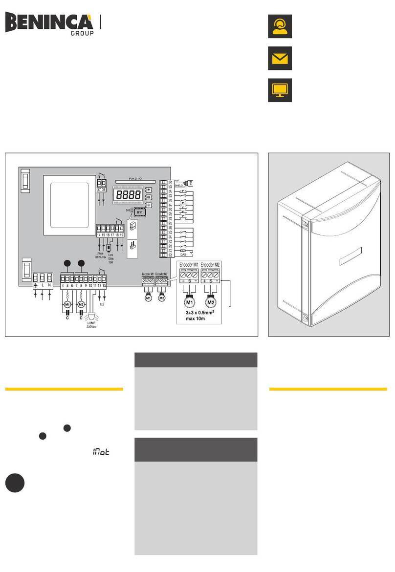
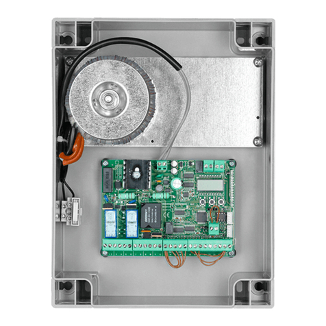
Nella seguente tabella sono descritti i collegamenti elettrici rappresentati in Fig. 1:
Morsetti Funzione Descrizione
L-N-GND Alimentazione
Ingresso 230Vac 50/60Hz (CP.MS5)
Ingresso 115Vac 50/60Hz (CP.MS5 115V))
(1-Fase/2-Neutro/GND-Collegamento di terra)
MOT-COM-MOT Motore Collegamento al motore:
(MOT-marcia/COM-Comune/MOT-marcia)
N-BLINK LAMP
Uscita collegamento Lampeggiante
CP.MS5: 230 Vac 40W max.
CP.MS5 115V: 115 Vac 40W max.
SWO SWO Ingresso finecorsa APERTURA (contatto N.C.)
SWC SWC Ingresso finecorsa CHIUSURA (contatto N.C.)
PHOT (CHIUDE) PHOT
Ingresso collegamento dispositivi di sicurezza, contatto N.C. (ad
es. fotocellule): comportamento configurabile tramite DIP3).
In modalità “Uomo Presente” assume la funzione comando CHIU-
DE, collegare in questo caso un pulsante N.O.
STOP STOP
Ingresso pulsante STOP (contatto N.C.)
Può assumere la funzione Chiude o Pedonale (contatto N.O.) vedi
paragrafo “Programmazione Avanzata”.
COM COM Comune per tutti gli ingressi di comando.
P.P. (APRE) Passo-Passo
Ingresso pulsante passo-passo (contatto N.O.).
Può assumere la funzione APRE vedi paragrafo “Programmazione
Avanzata”.
In modalità “Uomo Presente” assume la funzione comando APRE.
24 VAC 24Vac Uscita alimentazione accessori 24Vac/200mA max.
SCA SCA
Contatto libero da tensione non isolato per collegamento spia cancello
aperto.
Contatto aperto ad anta chiusa, intermittente durante il movimento
dell’anta, chiuso ad anta aperta.
ENC1 ENCODER Ingresso collegamento Encoder (opzionale).
Vedi paragrafo REGOLAZIONE RALLENTAMENTO
SHIELD-ANT Antenna Collegamento antenna scheda radioricevente incorporata
(SHIELD-schermo/ANT-segnale).
Nota:
La centrale dispone di un pulsante “P2” con la medesima funzionalità del pulsante Passo-Passo, utile per
comandare l’automazione durante la fase di installazione (solo con DIP2:OFF).
VERIFICA COLLEGAMENTI:
1) Togliere alimentazione.
2) Sbloccare manualmente la porta, portarla a circa metà della corsa e ribloccarla.
3) Ripristinare l’alimentazione.
4) Dare un comando di passo-passo mediante pulsante P2, ingresso P.P. o radiocomando.
5) La porta deve muoversi in apertura. Nel caso ciò non avvenisse, a motore fermo, è sufficiente invertire
tra loro i fili di marcia (MOT/MOT) del motore e dei finecorsa (SWO/SWC).
6) Procedere con le regolazioni descritte nel paragrafo “APPRENDIMENTO CORSA E RALLENTAMENTI”.

6
FUNZIONE DEI TRIMMER
TW Se installato il dispositivo Encoder, assume la funzione di regolazione sensibilità anti-
schiacciamento. Ruotando in senso orario aumenta la sensibililtà.
In assenza di dispositivo Encoder, regola la durata massima della manovra di apertura e
chiusura.
Deve essere impostato circa 4s in più rispetto al tempo di corsa effettiva dell’automatismo.
La regolazione varia da un minimo di 3s ad un massimo di 180s.
Se viene effettuato la procedura di apprendimento corsa e rallentamenti la posizione del
trimmer non ha effetto sul tempo di lavoro.
TCA Permette di regolare il tempo di chiusura automatica.
La regolazione varia da un minimo di 3s ad un massimo di 180s
Con il trimmer TCA completamente ruotato in senso orario, il LED DL2 (verde) si spegne,
il TCA è disattivato.
FUNZIONE DIP-SWITCH
Dip-Switches Funzione Descrizione
DIP1 Programmazione
Da utilizzare esclusivamente per la programmazione della coppia e
del tempo di prelampeggio e del rallentamento.
Una volta portato il DIP1 in ON:
- con il pulsante P1 si regola la coppia.
- con il pulsante P2 si attiva/disattiva il prelampeggio.
- con l’ingresso Passo/Passo o un telecomando memorizzato si
regola lo spazio di rallentamento.
Vedere i rispettivi paragrafi.
Una volta impostati i parametri, riportare in OFF.
DIP2 Condominiale
Abilita o disabilita la funzione condominiale.
Off: Funzione condominiale disabilitata.
On: Funzione condominiale abilitata.
L’impulso P.P. o del trasmettitore non ha effetto durante la fase di
apertura.
DIP3 PHOT: modalità
di funzionamento
Seleziona la modalità di funzionamento dell’ingresso PHOT
Off: Ingresso attivo sia in fase di apertura, sia in fase di chiusura
On: Ingresso attivo solo in fase di chiusura
DIP4 P.P. : modalità
di funzionamento
Seleziona la modalità di funzionamento del ”Pulsante P.P.” e del
trasmettitore.
Off: Funzionamento: APRE > STOP > CHIUDE > STOP >
On: Funzionamento: APRE > CHIUDE > APRE >
DIP5 Chiusura rapida
Abilita o disabilita la chiusura rapida (solo con TCA attivato)
Off: Chiusura rapida disabilitata
On: Chiusura rapida abilitata. L’intervento della fotocellula, comporta
dopo circa 3s la chiusura della porta.
DIP6 N/A
Vedi paragrafo PROGRAMMAZIONE AVANZATA

7
APPRENDIMENTO CORSA E RALLENTAMENTI
Per la regolazione degli spazi di rallentamento in apertura e chiusura, procedere come segue:
1) chiudere o aprire il cancello (assicurandosi che sia premuto il finecorsa di chiusura/aperura).
2) mettere a ON il DIP 1 (DIP 2-3-4-5-6=OFF)
3) dare un comando PP (tramite Ingresso Passo-Passo o telecomando memorizzato). Il cancello inizia a muo-
versi in apertura a velocità normale.
4) quando il cancello raggiunge il punto di rallentamento desiderato dare un altro comando PP, il cancello
inizierà a rallentare e proseguirà la corsa fino a completa apertura. Successivi comandi PP saranno ignorati.
5) con il cancello fermo e completamente aperto dare un comando PP (tramite Ingresso Passo-Passo o tele-
comando memorizzato). Il cancello inizia a muoversi in chiusura a velocita normale.
6) quando il cancello raggiunge il punto di rallentamento desiderato dare il comando PP, il cancello inizierà a
rallentare e proseguirà la corsa fino a completa chiusura. Altri comandi PP saranno ignorati.
7) riposizionare su OFF il dip1
NOTE:
- se non si desidera regolare lo spazio di rallentamento in apertura o in chiusura, lasciare che il cancello ese-
gua una manovra di completa apertura/chiusura senza dare un comando PP di inizio rallentamento.
- l’intervento di sicurezze come STOP e PHOT blocca la procedura di regolazione. Ripetere la procedura
dall’inizio.
- se è installato il dispositivo Encoder, durante la fase di apprendimento il sensore antischiacciamento è
disabilitato.
RESET APPRENDIMENTO CORSA E RALLENTAMENTI
Per riportare la centrale al funzionamento senza rallentamenti (funzionamento a tempo regolato dal
trimmer TW), procedere come segue:
1) Portare il cancello in una posizione intermedia, lontano dai finecorsa
2) Portare il DIP 1 su ON (DIP 2-3-4-5-6=OFF)
3) Dare un comando Passo/Passo tramite ingresso PP o telecomando
4) I LED lampeggiano a comferma del reset iniziato
5) Quando i LED si spengono riportare il DIP 1 su OFF
La centrale ha cancellato i dati relativi alla corsa e ai rallentamenti.
MODALITÀ UOMO PRESENTE
Portando tutti i DIP in ON la centrale passa in modalità UOMO PRESENTE.
L’ingresso PHOT assume la funzione Pulsante CHIUDE (collegare pulsante con contatto N.O.).
L’ingresso PP assume la funzione Pulsante APRE (collegare pulsante con contatto N.O.).
La pressione dei pulsanti APRE/CHIUDE deve essere mantenuta durante tutta la manovra. L’apertura
dell’ingresso STOP arresta il motore.
La pressione simultanea di APRE/CHIUDE comporta l’arresto del motore.
REGOLAZIONE COPPIA (DIP1:ON)
Appena spostato il DIP1 in ON la scheda segnala la coppia applicata in quel momento tramite un numero
di lampeggi (da 1 a 4) del LED verde DL2 seguiti da una pausa di 3s.
La coppia massima viene segnalata con il LED verde DL2 fisso.
Per incrementare la coppia premere il pulsante P1; il LED DL2 cambia il numero di lampeggi ad indicare
il valore di coppia selezionato.
Una volta selezionata la coppia desiderata, per apprendere tale impostazione, portare il DIP1 in OFF.

8
PROGRAMMAZIONE AVANZATA
Se necessario è’ possibile modificare la funzionalità degli ingressi PP e STOP per ottenere ingressi APRE/
CHIUDE o in alternativa APRE/PEDONALE, procedere come segue:
1) mettere tutti i DIP su OFF
2) mettere a ON il DIP1
3) per modificare l’ingresso Passo/Passo in Open portare il DIP 2 in ON
4) per modificare l’ingresso STOP in Chiude portare il DIP 3 in ON e il DIP 4 in OFF
5) per modificare l’ingresso STOP in Pedonale portare il DIP 4 in ON e il DIP 3 in OFF
6) mettere il DIP 6 su ON. I LED lampeggiano alterativamente per circa 10s.
7) dopo 10s i LED lampeggiano simultaneamente e viene memorizzata la nuova funzionalità degli ingressi
8) mettere a OFF i dip
9) riportare i DIP alle impostazioni desiderate
ATTIVAZIONE/DISATTIVAZIONE PRELAMPEGGIO (DIP1:ON)
Appena spostato il DIP1 in ON il led DL1 rosso segnala l’attivazione o meno del prelampeggio.
Con il pulsante P2 è possibile attivare o disattivare la funzione prelampeggio.
LED DL1 Acceso: Prelampeggio attivo, il lampeggiante si accende circa 3 secondi prima della partenza
del motore.
LED DL1 Spento. Prelampeggio disattivato.
APPRENDIMENTO RADIO (DIP1:OFF)
La centrale CP.MS5 è dotata di un modulo radio incorporato per la ricezione di telecomandi con codifica
ARC (Advanced Rolling Code), con frequenza di 433.92MHz.
Per utilizzare un telecomando è prima necessario apprenderlo, la procedura di memorizzazione è illustrata
di seguito, il dispositivo è in grado di memorizzare fino a 64 codici diversi.
Premendo P1 la centrale entra in fase di apprendimento radio: il LED rosso DL1 lampeggia 1 volta al
secondo in attesa del tasto da associare alla funzione Passo-Passo;
Una volta appreso il tasto si esce dalla programmazione;
Premendo 2 volte P1 il LED rosso DL1 lampeggia 2 volte al secondo ed entro nella fase di apprendimento
pedonale (la funzione pedonale comanda una manovra di apertura di 7s).
Una volta appreso il tasto da associare si esce dalla programmazione.
Nel caso in cui sia necessario uscire dalla programmazione senza apprendere nessun radiocomando,
premere il tasto il tasto P1 finchè il led rosso DL1 torna a lampeggiare in modalità “presenza rete“ (vedi
diagnostica LED pag. 7).
Per resettare la memoria della ricevente premere e mantenere premuti contemporanenamente i tasti P1 e
P2 per circa 10 secondi (durante questo tempo entrambi i LED DL1 e DL2 lampeggiano velocemente).
Trascorsi i 10 secondi i due LED restano accesi fissi, rilasciare i pulsanti.
Quando i LED tornano nella configurazione iniziale la centralina ha effettuato il reset della memoria.
NOTA:
I trasmettitori vengono memorizzati su un memoria EPROM (U2) che può essere rimossa dalla centrale e
reinserita in una nuova centrale CP.MS5 in caso di sostituzione.
Per motivi di sicurezza, non è possibile memorizzare trasmettitori durante le fasi apertura/chiusura del
motore.
APPRENDIMENTO REMOTO TRASMETTITORI
Se si dispone di un trasmettitore già memorizzato nella ricevente è possibile effettuare l’apprendimento
radio remoto (senza necessità di accedere alla centrale).
IMPORTANTE: La procedura deve essere eseguita con ante in apertura durante la pausa TCA.
Procedere come segue:
1 Premere il tasto nascosto del trasmettitore già memorizzato.
2 Premere, entro 5s, il tasto del trasmettitore già memorizzato corrispondente al canale da associare al
nuovo trasmettitore. Il lampeggiante si accende.
3 Premere entro 10s il tasto nascosto del nuovo trasmettitore.
4 Premere, entro 5s, il tasto del nuovo trasmettitore da associare al canale scelto al punto 2. Il lampeggiante
si spegne.
5 La ricevente memorizza il nuovo trasmettitore ed esce immediatamente dalla programmazione.

9
DIAGNOSTICA LED
Il LED DL1 rosso segnala l’attivazione degli ingressi, secondo questa legenda:
STOP acceso fisso
PHOT lampeggio veloce
SWO 1 lampeggio con pausa di 2 secondi
SWC 2 lampeggi con pausa di 2 secondi
Il LED DL1 rosso segnala anche la presenza di rete con lampeggio lento.
Il LED DL2 verde segnala la direzione del movimento del motore e lo stato del cancello, secondo questa
legenda:
APERTURA 1 lampeggio con pausa di 1 secondo
CHIUSURA 2 lampeggi con pausa di 1 secondo
Cancello aperto senza TCA acceso fisso
Cancello aperto con TCA lampeggio veloce
Cancello chiuso led spento
SMALTIMENTO
Come indicato dal simbolo a lato, è vietato gettare questo prodotto nei rifiuti domestici in
quanto alcune parti che lo compongono potrebbero risultare nocive per l’ambiente e la salute
umana, se smaltite scorrettamente. L’apparecchiatura, pertanto, dovrà essere consegnata
in adeguati centri di raccolta differenziata, oppure riconsegnata al rivenditore al momento
dell’acquisto di una nuova apparecchiatura equivalente. Lo smaltimento abusivo del prodotto
da parte dell’utente comporta l’applicazione delle sanzioni amministrative previste dalla
normativa vigente.
DATI TECNICI
Alimentazione di rete 230 Vac 50/60 Hz (115 Vac 50/60Hz CP.MS5 115)
Uscita Motore 1 motore 230 Vac (115Vac CP.MS5 115)
Potenza massima motore 750 W
Uscita alimentazione accessori 24Vdc 200mA max.
Grado di protezione IP 40
Temp. funzionamento -20°C / +50°C
Ricevitore radio 433,92 MHz incorporato ARC (Advanced Rolling Code)
N° codici memorizzabili 64

10
WARNINGS
This manual has been especially written to be use by quali-
fied fitters.
None of the information provide in this manual can be con-
sidered as being of interest for the end users.
Preserve this manual for future needs.
The technician has to furnish all the information related to the
step by step function, the manual and the emergency function
of the operator, and to deliver the manual to the final user.
•Foresee on the supply net an onnipolar switch or
selector with distance of the contacts equal or
superior to 3 mms.
Verify that of the electrical system there is an awry differential
interrupter and overcurrent protection.
Some typologies of installation require the connection of the
shutter to be link at a conductive mass of the ground accord-
ing to the regulations in force.
The electrical installation and the operating logic must comply
with the regulations in force.
The leads fed with different voltages must be physically
separate, or they must be suitably insulated with additional
insulation of at least 1 mm.
The leads must be secured with an additional fixture near
the terminals.
During installation, maintenance and repair, interrupt the
power supply before opening the lid to access the electri-
cal parts
Check all the connections again before switching on the
power.
The unused N.C. inputs must be bridged.
The descriptions and the present illustrations in this manual
are not binding. Leaving the essential characteristics of the
product unchanged, the manufacturer reserves himself the
right to bring any change of technical, constructive or com-
mercial character without undertaking himself to update the
present publication.
CE Declaration of Conformity
Declaration in accordance with Directives 2004/108/CE (EMC); 2006/95/CE (LVD)
The Manufacturer:
AUTOMATISMI BENINCÀ SPA
Address:
Via Capitello, 45 - 36066 Sandrigo (VI) - Italy
Declares that the product:
Control box for 1 motor:
CP.MS5
conforms with the requirements of the following EU Directives:
• DIRECTIVE 2004/108/CE OF THE EUROPEAN PARLIAMENT AND COUNCIL, 15 December 2004,
in relation to the harmonisation of the legislation of member states regarding electromagnetic compatibility , in
abrogation of Directive 89/336/CEE, per the following harmonised standards:
EN 61000-6-2:2005, EN 61000-6-3:2007.
• DIRECTIVE 2006/95/CE OF THE EUROPEAN PARLIAMENT AND COUNCIL, 12 December 2006, in
relation to the harmonisation of the legislation of member states regarding electrical material intended to be used
within certain voltage ranges, per the following harmonised standards:
EN 60335-1:2002 + A1:2004 + A11:2004 + A12:2006 + A2:2006 + A13:2008; EN 60335-1-103:2003.
as applicable:
• DIRECTIVE 1999/5/CE OF THE EUROPEAN PARLIAMENT AND COUNCIL, 9 March 1999 in relation
to radio equipment and telecommunications terminals and the mutual recognition of their
conformity, per the following harmonised standards:
ETSI EN 301 489-3 V1.4.1 (2002) + ETSI EN 301 489-1 V1.4.1 (2002) + ETSI EN 300 220-3 V1.1.1 (2000) +
EN 60950-1 (2001)
Benincà Luigi, Legal representative.
Sandrigo, 22/10/2015.

11
CONTROL PANEL CP.MS5
WIRE DIAGRAM
Wire connections shown in Fig. 1 are described hereunder:
Terminals Function Description
L-N-GND Power supply
Input, 230VAC 50Hz (CP.MS5)
Input, 115VAC 50/60Hz (CP.MS5 115V))
(1-Phase/2-Neutral/GND-Ground connection)
MOT-COM-MOT Motor Connection to motor:
(MOT-move/COM-Common/MOT-move)
N-BLINK LAMP
Output, connection to Flashing light
CP.MS5: 230 Vac 40W max.
CP.MS5 115V: 115 Vac 40W max.
SWO SWO Input, OPENING limit switch (Normally Closed contact)
SWC SWC Input, CLOSING limit switch (Normally Closed contact)
PHOT (CLOSE) PHOT
Input, connection to safety devices, Normally Closed (N.C.) contact
(e.g. photocells): configurable through DIP3).
In “Service man” mode, it activates the CLOSE function. In this
case connect a Normally Open (N.O.) key.
STOP STOP
Input, STOP key (N.C. contact)
Can assume the Close or Pedestrian function (contact N.O.) see
“Advanced Programming” paragraph.
COM COM Common, all control inputs.
P.P. (OPEN) Step-by-Step
Input, step-by-step key (N.O. contact).
Can assume the OPEN function see paragraph “Advanced Pro-
gramming”.
In “Service man” mode, it activates the OPEN control function.
24 VAC 24Vac Output, 24Vac/200mA max accessory power supply.
SCA SCA
Contact free from voltage, not insulated for the connection of open
gate indicator lamp.
Open contact with closed door leaf. Flashing light during the door
leaf movement. With open door leaf, the contact is closed.
ENC1 ENCODER Input, connection of the encoder (OPTIONAL).
See section HOW TO ADJUST BRAKING
SHIELD-ANT Antenna Connection of the antenna to the incorporated radio-receiver module
(SHIELD-screen/ANT-signal).
Note:
The control unit uses a “P2” key with the same functions of the Step-by-Step push-button. This is useful
to control the automatic system during installation (only with DIP2: OFF).
CHECKING CONNECTIONS:
1) Cut off power supply.
2) Manually release the door, move it at around half stroke and lock it again.
3) Reset power supply.
4) Send the step-by-step (P.P.) control signal through the P2 key, P.P. or remote control.
5) The door leaves should open. If not, with stopped motor, it is sufficient to invert the move wires of the
motor (MOT/MOT) of the motor and the limit switches (SWO/SWC).
6) Proceed with regulations described in “STROKE ACQUISITION & SLOWDOWNS”

12
TRIMMER FUNCTIONS
TW If the Encoder device is installed, it assumes the function of regulating anti-crushing
sensitivity. When turned in a clockwise direction, sensitivity is increased.
In the absence of an Encoder device, regulate the maximum duration of opening and closing
manoeuvres.
It must be preset approx. 4s more with respect to the actual stroke time of the system.
The adjustment ranges from 3s to 180s maximum.
If the stroke acquisition and slowdowns procedure is executed, the position of the trimmer has no
effect on the operation time.
TCA It allows to adjust the automatic closure time.
The adjustment ranges from 3s to 180s maximum.
With TCA trimmer completely turned clockwise, the DL2 LED (green) switches off, TCA is
deactivated.
DIP-SWITCH FUNCTION
Dip-Switches Function Description
DIP1 Set-up
To be used only for the setting-up of the torque and the forewar-
ning and braking time.
After moving DIP1 to ON:
- with P1 push-button the torque is adjusted.
- with push-button P2 the forewarning light is activated/deactiva-
ted.
- with the Step-by-Step input or a memorised remote control,
braking length is adjusted.
See the related sections.
After presetting the parameters, move to OFF.
DIP2 Multi-flat
The multi-flat function is enabled or disabled.
Off: disabled multi-flat function.
On: enabled multi-flat function.
The P.P. (Step-by-step) impulse or the impulse of the transmitter
have no effect in the opening phase.
DIP3 PHOT: operating
mode
The operating mode of the PHOT input is selected
Off: Input, activated in both opening and closing phases
On: Input, activated in the closing phase only
DIP4 P.P.: operating
mode
The operating mode of the “P.P. push-button” and the transmitter
are selected.
Off: Operation: OPEN > STOP > CLOSE > STOP >
On: Operation: OPEN > CLOSE > OPEN >
DIP5 Rapid closure
The rapid closure is enabled or disabled with (only with activated
TCA)
Off: disabled rapid closure
On: enabled rapid closure. The triggering of the photocell involves,
after approx. 3s, the closure of the door.
DIP6 N/D See section ADVANCED PROGRAMMING

13
STROKE ACQUISITION & SLOWDOWNS
To adjust braking length in both opening and closing phases, proceed as follows:
1) Close or open the gate (make sure that the closing/opening limit switch is pressed).
2) Move DIP 1 to ON (DIP 2-3-4-5-6=OFF)
3) Send PP control signal (through Step-by-Step Input or memorised remote control). The gate starts opening
at normal speed.
4) When the gate reaches the desired braking point, send another PP control signal, the gate will start braking
until it is completely opened. Subsequent PP control signals will be ignored.
5) With totally open and stopped gate, send a PP control signal (through Step-by-Step Input or memorised
remote control) The gate starts closing at normal speed.
6) When the gate reaches the desired braking point, send another PP control signal, the gate will start braking
until it is completely closed. Subsequent PP control signals will be ignored.
7) Move DIP1 to OFF again.
NOTE:
- if braking length does not require any adjustment in both opening and closing, leave the gate to totally
open/close without sending a PP control signal to start braking.
- If safety functions (STOP and PHOT) are activated, the adjustment procedure will be blocked. Repeat the
procedure from the beginning.
- During this phase, the anti-crash sensor is disabled.
- if the Encoder device is installed, the anti-crushing sensor is disabled during the acquisition phase.
RESET STROKE ACQUISITION & SLOWDOWNS
To set the control unit to function without slowdowns (timed operation regulated by TW trimmer), proceed as
follows:
1) Move the gate to an intermediate position, far from the limit switches
2) Move DIP 1 to ON (DIP 2-3-4-5-6=OFF)
3) Give the Step/Step command through the PP input or remote control
4) The flashing LEDs will confirm the initiated reset
5) When the LEDs turn off, move DIP 1 to OFF
The control unit has deleted data relative to the stroke and slowdowns.
SERVICE MAN MODE
With all DIPs on ON, the control unit switches to SERVICE MAN mode.
The PHOT input has the CLOSE push-button function (connect the button with N.O. contact).
The PP input has the OPEN push-button function (connect the button with N.O. contact).
The OPEN/CLOSE push-buttons must be kept pressed during operation. The opening of the STOP input
stops the motor.
The contemporary pressure of OPEN/CLOSE stops the motor.
ADJUSTMENT OF THE TORQUE (DIP1:ON)
When DIP1 is moved to ON, the board indicates that the torque has been applied during a number of
flashes (from 1 to 4) of the DL2 green LED, followed by a 3-s interval.
The max torque is indicated with DL2 green LED with fixed light.
To increase the torque, press P1. The DL2 LED changes the number of flashes to indicate the selected
torque value.
Once the desired torque is selected, move DIP 1 to OFF to memorise this presetting.

14
ADVANCED PROGRAMMING
If necessary, it is possible to modify the functions of the PP and STOP inputs to obtain OPEN/CLOSE inputs
or alternatively OPEN/PEDESTRIAN inputs; proceed as follows:
1) Move all DIPs to OFF
2) Move DIP1 to ON
3) to change the Step/Step input to Open, move DIP 2 to ON
4) to change the STOP input to Close, move DIP 3 to ON and DIP 4 to OFF
5) to change the STOP input to Pedestrian, move DIP 4 to ON and DIP 3 to OFF
6) move DIP 6 to ON. The LEDs will flash alternatively for approx. 10 secs.
7) after 10 seconds, the LEDs will flash simultaneously and the new input functions will be stored.
8) move the dips to OFF
9) move the DIPs back to the desired settings
PRE-WARNING ACTIVATION/DEACTIVATION (DIP1:ON)
As soon as DIP1 is to ON, the DL1 red LED indicates whether the pre-warning flashing is activated.
The pre-warning function can be activated or deactivated with P2 key.
LED DL1 On: Activated pre-warning, the indicator lamp switches on for approx. 3 seconds before the
motor starts.
LED DL1 Off. Pre-warning is deactivated.
RADIO SELF-LEARNING (DIP1:OFF)
The CP.MS5 control unit is fitted with an incorporated radio module to receive transmitters with ARC
coding (Advanced Rolling Code), with a frequency of 433.92MHz.
To use a remote control, it is first necessary to store its code in memory. The memorisation procedure is
described hereunder. The device is able to store up to 64 different codes in memory.
By pressing P1, the control unit enters the radio learning phase: DL1 red LED flashes 1 time per second,
awaiting the key to the matched to the Step-by-Step function;
When the key is stored in memory, exit from the programming mode;
By pressing P1 twice, the DL1 red LED flashes 2 times per second and the pedestrian learning phase is
entered (the pedestrian function controls an opening operation of 7s).
When the key to be matched is memorised, exit from the programming mode.
If the programming mode must be left without storing any remote control signal, press P1 key until DL1
red LED starts to flash in “power on” mode (see LED diagnostics on page 7).
To reset the memory of the receiver, press and keep P1 and P2 keys pressed for around 10 seconds
(during this period of time, both DL1 and DL2 flash rapidly).
After 10 seconds, when the two LEDs are switched on with fixed light, release the push-buttons.
When the LEDs switch back again to the original configuration, the control unit has completed the memory
reset.
NOTE:
The transmitters are memorised on an EPROM memory (U2), which can be extracted from the control unit
and inserted in a new CP.MS5 control unit should a replacement is required.
For safety reasons, the transmitters can be stored in memory during the opening/closing of the motor.
TRANSMITTER REMOTE LEARNING
If the transmitter code is already stored in the receiver, the remote radio learning can be carried out
(without accessing the control unit).
IMPORTANT: The procedure should be carried out with gate in the opening phase, during the TCA
dwell time.
Proceed as follows:
1 Press the hidden key of the transmitter, the code of which has already been stored in memory.
2 Within 5 seconds, press the already memorised transmitter key corresponding to the channel to be
matched to the new transmitter. The flashing light switches on.
3 Within 10 seconds, press the hidden key of the new transmitter.
4 Within 5 seconds, press the key of the new transmitter to be matched to the channel selected at item 2.
The flashing light switches off.
5 The receiver stores the new transmitter code and exits from the programming mode immediately.

15
SPECIFICATIONS
Mains power supply 230 VAC 50/60 Hz (115 VAC 50/60Hz CP.MS5 115)
Output, Motor 1 motor, 230 VAC (115VAC CP.MS5 115)
Motor maximum power 750 W
Output, power supply of accessories 24VDC 200mA max.
Protection level IP 40
Operating temperature -20°C / +50°C
Radio receiver 433.92 MHz, incorporated ARC (Advanced Rolling Code)
No. of codes storable in memory 64
LED DIAGNOSTICS
The red LED DL1 indicates the activation of inputs according to the legend hereunder:
STOP on with fixed light
PHOT rapid flashing
SWO 1 flash with 2-second interval
SWC 2 flashes with 2-second interval
By flashing slowly, the red LED DL1 also indicates that the unit is powered.
The green LED DL2 indicates the movement direction of the motor and the status of the gate according
to the legend hereunder:
OPENING 1 flash with 1-second interval
CLOSING 2 flashes with 1-second interval
Open gate without TCA on with fixed light
Open gate with TCA rapid flash
Closed gate LED off
WASTE DISPOSAL
As indicated by the symbol shown, it is forbidden to dispose this product as normal urban
waste as some parts might be harmful for environment and human health, if they are disposed
of incorrectly. Therefore, the device should be disposed in special collection platforms or given
back to the reseller if a new and similar device is purchased. An incorrect disposal of the device
will result in fines applied to the user, as provided for by regulations in force.

16
HINWEISE
Dieses Handbuch ist ausschließlich qualifiziertem Personal für
die Installation und Wartung von automatischen Öffnungsvor-
richtungen bestimmt.
Es enthält keine Informationen die für den Endbenutzer inte-
ressant oder nützlich sein könnten.
Bewahren Sie dieses Handbuch für Nachschlagzwecke auf.
Der Installateur hat dem Benutzer alle Informationen über den
automatischen, manuellen und Not-Betrieb der Automatik
zusammen mit der Bedienungsanleitung zu liefern.
•Das Stromnetz muss mit einem allpoligen Schalter
bzw. Trennschalter ausgestattet sein, dessen
Kontakte einen Öffnungsabstand gleich oder
größer als 3 aufweisen.
Kontrollieren ob der elektrischen Anlage ein geeigneter
Differentialschalter und ein Überspannungsschutzschalter
vorgeschaltet sind.
Einige Installationstypologien verlangen den Anschluss des
Flügels an eine Erdungsanlage laut den geltenden Sicher-
heitsnormen.
Die elektrische Installation und die Betriebslogik müssen den
geltenden Vorschriften entsprechen.
Die Leiter die mit unterschiedlichen Spannungen gespeist
werden, müssen physisch getrennt oder sachgerecht mit
einer zusätzlichen Isolierung von mindestens 1 mm isoliert
werden.
Die Leiter müssen in der Nähe der Klemmen zusätzlich
befestigt werden.
Während der Installation, der Wartung und der Reparatur, die
Anlage stromlos machen bevor an den elektrischen Teilen
gearbeitet wird.
Alle Anschlüsse nochmals prüfen, bevor die Zentrale mit
Strom versorgt wird.
Die nicht verwendeten N.C. Eingänge müssen überbrückt
werden.
Die in diesem Handbuch enthaltenen Beschreibungen und
Abbildungen sind nicht verbindlich. Ausgenommen der
Haupteigenschaften des Produkts, behält sich der Hersteller
das Recht vor eventuelle technische, konstruktive oder kom-
merzielle Änderungen vorzunehmen ohne dass er vorliegende
Veröffentlichung auf den letzten Stand bringen muss.
CE-Konformitätserklärung
Erklärung im Einklang mit den Richtlinien 2004/108/CE(EMC); 2006/95/CE(LVD)
Hersteller:
Automatismi Benincà SpA
Anschrift:
Via Capitello, 45 - 36066 Sandrigo (VI) - Italien
Erklärt, dass das Produkt:
Steuerung für 1 Motoren:
CP.MS5
die Bedingungen der folgenden CE-Richtlinien erfüllt:
• RICHTLINIE 2004/108/CE DES EUROPÄISCHEN PARLAMENTS UND EUROPARATS vom 15.
Dezember 2004 in Bezug auf die Annäherung der Rechtsprechungen der Mitgliedsstaaten über die elektromag-
netische Kompatibilität, welche die Richtlinie 89/336/CEE laut den folgenden harmonisierten Normen:
EN 61000-6-2:2005, EN 61000-6-3:2007.
• RICHTLINIE 2006/95/CE DES EUROPÄISCHEN PARLAMENTS UND EUROPARATS vom 12.
Dezember 2006 in Bezug auf die Annäherung der Rechtsprechungen der Mitgliedsstaaten über elektrische Be-
triebsmittel zur Verwendung innerhalb bestimmter Spannungsgrenzen laut den folgenden harmonisierten Normen:
EN 60335-1:2002 + A1:2004 + A11:2004 + A12:2006 + A2:2006 + A13:2008; EN 60335-1-103:2003.
falls anwendbar:
• RICHTILINIE 1999/5/CE DES EUROPÄISCHEN PARLAMENTS UND EUROPARATS vom 9. März
1999 in Bezug auf Funkapparate und Telekommunikations-Endgeräte und die gegenseitige Anerkennung ihrer
Konformität entsprechend den folgenden harmonisierten Normen:
ETSI EN 301 489-3 V1.4.1 (2002) + ETSI EN 301 489-1 V1.4.1 (2002) + ETSI EN 300 220-3 V1.1.1 (2000)
+ EN 60950-1 (2001)
Benincà Luigi, Leiter der Rechtsabteilung.
Sandrigo, den 22/10/2015.

17
STEUEREINHEIT CP.MS5
ELEKTRISCHE ANSCHLÜSSE
In der nachstehenden Tabelle sind die elektrischen und in Abb. 1 dargestellten Anschlüsse beschrieben:
Klemmen Funktion Beschreibung
L-N-GND Speisung
Eingang 230Vac 50/60Hz (CP.MS5)
Eingang 115Vac 50/60Hz (CP.MS5 115v)
(1 Phase/2 Nulleiter/GND Erdung)
MOT-COM-
MOT Motor Anschluss an den Motor:
(MOT Betrieb/COM Gemein/MOT Betrieb)
N-BLINK LAMP
Ausgang Anschluss Blinkleuchte
CP.MS5: 230 Vac 40W max.
CP.MS5 115V: 115 Vac 40W max.
SWO SWO Eingang Endschalter ÖFFNEN (Kontakt N.C.)
SWC SWC Eingang Endschalter SCHLIESSEN (Kontakt N.C.)
PHOT
(SCHLIESSEN) PHOT
Eingang Anschluss Sicherheitsvorrichtungen, Kontakt N.C. (z.B. Foto-
zellen): Kann über den Dip-Schalter DIP3 konfiguriert werden).
Im Modus „Mann vorhanden“ übernimmt die Vorrichtung die Steue-
rung SCHLIESSEN. In diesem Fall einen Schalter N.O. anschließen.
STOP STOP
Eingang Taste STOP (Kontakt N.C.).
Die Funktion “Schließen” oder “Halb Schließen” (Kontakt N.O.) kann
übernommen werden. Siehe Abschnitt “Erweiterte Programmierung”.
COM COM Gemein für alle Steuerungseingänge.
P.P. (ÖFFNEN) Schritt-Schritt
Eingang Taste Schritt-Schritt (Kontakt N.O.).
Die Funktion “ÖFFNEN” kann übernommen werden. Siehe Abschnitt
“Erweiterte Programmierung”.
Im Modus „Mann vorhanden“ übernimmt die Vorrichtung die Steue-
rung ÖFFNEN.
24 VAC 24Vac Ausgang Speisung Zubehör 24Vac/200mA max.
SCA SCA
Stromloser nicht isolierter Kontakt zum Anschluss der Meldeleuchte
Tor offen. Offener Kontakt bei geschlossenem Flügel, aussetzend
während der Flügelbewegung, geschlossen bei offenem Flügel.
ENC1 ENCODER Eingang Encoder-Anschluss (OPTIONAL).
Siehe Paragraph „REGELUNG DER GESCHWINDIGKEITSABNAHME“.
SHIELD-ANT Antenne Anschluss Antenne Platine des eingebauten Funkempfängers
(SHIELD-Bildschirm/ANT-Signal).
Bemerkung:
Die Zentrale verfügt über eine Taste „P2“ mit derselben Funktion der Taste Schritt-Schritt, die zur
Steuerung der Automation während der Installation nützlich ist (nur mit DIP2:OFF).
ANSCHLÜSSE ÜBERPRÜFEN:
1) Stromversorgung abtrennen.
2) Von Hand die Tür entsichern, auf halben Hub bringen und wieder blockieren.
3) Stromversorgung wieder herstellen.
4) Eine Schritt-Schritt-Steuerung durch die Taste P2 am Eingang P.P. oder an der Fernbedienung geben.
5) Die Tür muss sich öffnen. Falls dies nicht der Fall sein sollte, genügt es die Betriebsleiter (MOT/MOT)
des Motors und der Endschalter (SWO/SWC) bei ausgeschaltetem Motor zu vertauschen.
6) Mit den im Abschnitt “ÜBERNAHME VON LAUF UND VERLANGSAMUNG” beschriebenen Einstellungen
fortfahren.

18
TRIMMER-FUNKTIONEN
TW Falls das Encoder-Gerät installiert ist, ist die Funktion der Druckempfindlichkeitseinstellung
zu übernehmen. Durch das Drehen im Uhrzeigersinn wird die Empfindlichkeit erhöht.
Falls kein Encoder-Gerät vorhanden ist, wird die maximale Dauer des Öffnungs- und
Schließverfahrens reguliert.
Muss um circa 4 sec. länger als die Zeit für den tatsächlichen Hub der Automatik
eingestellt werden.
Die Zeit kann zwischen 3 sec. und maximal 180 sec. eingestellt werden.
Wenn das Verfahren zur Übernahme von Lauf und Verlangsamung abgeschlossen ist, hat die
Trimmerposition keine Auswirkungen auf die Arbeitszeit.
TCA Damit kann die Zeit des automatischen Schließvorgangs eingestellt werden.
Die Zeit kann zwischen 3 sec. und maximal 180 sec. eingestellt werden.
Den Trimmer bis zum Anschlag im Uhrzeigersinn drehen. Die LED DL2 (grün) erlischt und
TCA wird aktiviert.
DIP-SCHALTER-FUNKTION
Dip-Schalter Funktion Beschreibung
DIP1 Programmierung
Nur zur Programmierung des Drehmoments, der Vorblink-Zeit und
der Geschwindigkeitsabnahme zu verwenden.
DIP1 auf ON schalten und:
- über die Taste P1 das Drehmoment einstellen
- über die Taste P2 das Vorblinken aktivieren/deaktivieren
- über den Eingang Schritt/Schritt oder die gespeicherte
Fernbedienung wird der Raum zur Geschwindigkeitsabnahme
geregelt.
Siehe die entsprechenden Paragraphen.
Nachdem die Parameter eingerichtet worden sind, wieder auf OFF
schalten.
DIP2 Wohngemeinschaft
Aktiviert oder deaktiviert die Funktion Wohngemeinschaft.
Off: Funktion Wohngemeinschaft deaktiviert.
On: Funktion Wohngemeinschaft aktiviert.
Auf den Öffnungsvorgang haben weder der Schritt-Schritt-Impuls
noch der Impuls des Sendegeräts Einfluss.
DIP3 PHOT: Betrieb-
smodus
Wählt die Betriebsweise des Eingangs PHOT.
Off: Eingang beim Öffnen und Schließen aktiv
On: Eingang nur beim Schließen aktiv
DIP4 P.P. : Betriebsmo-
dus
Wählt die Betriebsweise der “Taste P.P.” und des Sendegeräts.
Off: Betrieb: ÖFFNEN > STOP > SCHLIESSEN > STOP >
On: Betrieb: ÖFFNEN > SCHLIESSEN > ÖFFNEN
DIP5 Schnelles
Schließen
Aktiviert oder deaktiviert den schnellen Schließvorgang.(nur wenn
TCA aktiv)
Off: Schnelles Schließen deaktiviert
On: Schnelles Schließen aktiviert. Das Einschalten der Fotozelle
hat nach 3s das Schließen der Tür zur Folge.
DIP6 N/D
Siehe Paragraph „ERWEITERETE PROGRAMMIERUNG“.

19
ÜBERNAHME VON LAUF UND VERLANGSAMUNG
Um den Raum für die Geschwindigkeitsabnahme beim Öffnen und Schließen einzustellen, folgenderma-
ßen vorgehen:
1) Das Tor schließen oder öffnen (vergewissern Sie sich, dass der Endschalter für das Schließen/Öffnen
gedrückt worden ist)
2) Den DIP 1 auf ON schalten
(DIP 2-3-4-5-6=OFF)
3) Eine Schritt-Schritt-Steuerung durch den Eingang Schritt-Schritt oder die Fernbedienung geben. Das
Tor öffnet sich bei normaler Geschwindigkeit.
4) Wenn das Tor den Punkt erreicht, an dem die Geschwindigkeit abnehmen soll, nochmals eine Schritt-
Schritt-Steuerung geben. Das Tor verlangsamt die Geschwindigkeit bis zur vollständigen Öffnung. Weitere
Schritt-Schritt-Steuerungen werden danach nicht mehr berücksichtigt.
5) Bei stillstehendem und vollständig geöffnetem Tor, eine Schritt-Schritt-Steuerung durch den Eingang
Schritt-Schritt oder die Fernbedienung geben. Das Tor schließt sich bei normaler Geschwindigkeit.
6) Wenn das Tor den Punkt erreicht, an dem die Geschwindigkeit abnehmen soll, nochmals eine Schritt-
Schritt-Steuerung geben. Das Tor verlangsamt die Geschwindigkeit bis es vollständig geschlossen ist.
Weitere Schritt-Schritt-Steuerungen werden danach nicht mehr berücksichtigt.
7) Den DIP1 wieder auf OFF schalten.
BEMERKUNGEN:
- Falls das Tor beim Öffnen oder Schließen seine Geschwindigkeit nicht verlangsamen soll, lassen Sie die
Bewegung durchführen ohne die Schritt-Schritt-Steuerung zu geben.
- Das Einschalten der Sicherheiten STOPP und PHOT blockieren die Regelungsprozedur. Wiederholen Sie
den Vorgang von Anfang an.
- Während dieser Phase ist der Quetschsicherheitssensor deaktiviert.
- wenn das Encoder-Gerät installiert ist, wird der Anti-Drucksensor während der Übernahmephase
deaktiviert.
ÜBERNAHME VON LAUF UND VERLANGSAMUNG ZURÜCKSETZEN
Um das Gerät ohne Verzögerungen in Betrieb zu setzen (Laufzeit mittels Trimmer TW einstellbar), ist
folgendermaßen vorzugehen:
1) Das Tor ist, weit entfernt vom Grenzschalter, in eine Zwischenposition zu versetzen
2) Den DIP 1 auf AN stellen
(DIP 2-3-4-5-6=OFF)
3) Einen Befehl Schritt/Schritt mittels PP-Eingang oder Fernbedienung abgeben
4) Die LED-Lampen blinken zur Bestätigung des eingeleiteten Rücksetzens
5) Sobald die LED-Lampen erlischen, ist der DIP 1 auf AUS zu stellen.
Die Daten hinsichtlich des Laufes und der Verlangsamung sind vom Gerät gelöscht worden.
BETRIEB IM MODUS „MANN VORHANDEN“
Wenn alle DIP-Schalter auf ON geschaltet sind, schaltet die Zentrale auf den Modus „Mann vorhanden“.
Der Eingang PHOT übernimmt in diesem Fall die Funktion des Schalters SCHLIESSEN (Schalter mit
Kontakt N.O. anschließen).
Der Eingang PP übernimmt in diesem Fall die Funktion ÖFFNEN (Schalter mit Kontakt N.O. anschließen).
Die Tasten ÖFFNEN/SCHLIESSEN müssen während der gesamten Dauer der Steuerung gedrückt
bleiben. Das Öffnen des Eingangs STOP hält den Motor an.
Das gleichzeitige Drücken der Tasten ÖFFNEN/SCHLIESSEN hält den Motor an.
DREHMOMENT EINSTELLEN (DIP1: ON)
Nachdem der Dip-Schalter DIP1 auf ON geschaltet worden ist, wird das verwendete Drehmoment durch die
Anzahl der Blinksignale (1 bis 4) der grünen LED DL2 (mit jeweils einer Pause von 3s) angezeigt.
Das maximale Drehmoment wird durch die fest leuchtende grüne LED DL2 angezeigt.
Um das Drehmoment zu erhöhen, die Taste P1 drücken; die LED DL2 wechselt die Anzahl der Blinksignale,
um das gewählte Drehmoment anzuzeigen. Nachdem das gewünschte Drehmoment angezeigt worden
ist, DIP1 auf OFF schalten, um die Lernfunktion zu aktivieren.

20
ERWEITERETE PROGRAMMIERUNG
Falls erforderlich, lässt sich die Funktionalität der PP und STOP ändern, um Eingänge OFFEN/
GESCHLOSSEN oder alternativ OFFEN/HALB GESCHLOSSEN zu erhalten. Dafür ist folgendermaßen
vorzugehen:
1) alle DIP auf AUS schalten
2) DIP1 auf AN stellen
3) zur Änderung des offenen Eingangs Schritt/Schritt ist DIP2 auf AN zu stellen
4) zur Änderung des geschlossenen Eingangs STOP ist DIP3 auf AN und DIP4 auf AUS zu stellen
5) zur Änderung des Eingangs STOP in Gangschaltung ist DIP4 auf AN und DIP3 auf AUS zu stellen
6) Den DIP 6 auf AN stellen Die LED-Lampen blinken abwechselnd für ca. 10 Sek.
7) nach 10 Sek. blinken die LED-Lampen gleichzeitig und die neue Funktionalität der Eingänge wird
gespeichert
8) Die DIP auf AUS stellen
9) Die DIP in die gewünschten Einstellungen bringen
VORBLINKEN AKTIVIEREN/DEAKTIVIEREN (DIP1: ON)
Nachdem der Dip-Schalter DIP1 auf ON geschaltet worden ist, meldet die rote LED DL1 die Aktivierung
oder Deaktivierung des Vorblinkens.
Über die Taste P2 kann das Vorblinken aktiviert oder deaktiviert werden.
LED DL1 ein: Das Vorblinken ist aktiv, die Blinkleuchte schaltet circa 3 Sekunden vor dem Einschalten des
Motors ein.LED DL1 aus: Vorblinken deaktiviert.
FUNKMODUL UND SELBSTLERNFUNKTION (DIP1:OFF)
Das Gerät CP.MS5 verfügt über ein eingebettetes Funkmodul zum Empfang von Sendern mit Kodierung
ARC (Advanced Rolling Code), mit einer Frequenz von 433,92 MHz.
Um eine Fernbedienung verwenden zu können, muss sie zuerst erlernt werden; die Speicherungsprozedur
ist nachstehend beschrieben; die Vorrichtung kann bis zu 64 verschiedene Codes speichern.
Um die Zentrale auf die Lernfunktion zu schalten, Taste P1 drücken. Die rote LED DL1 blinkt 1 Mal pro
Sekunde bis die Taste gedrückt wird, die der Funktion Schritt-Schritt zugeordnet werden soll.
Nachdem die Taste gespeichert worden ist, wird die Programmierung beendet.
Um die Zentrale auf die Fußgängerfunktion zu schalten, die Taste P1 2 Mal drücken. Die rote LED
DL1 blinkt 2 Mal pro Sekunde und die Funktion ist abgerufen (die Fußgängerfunktion steuert einen
Öffnungsvorgang, der 7s dauert).
Nachdem die Taste gespeichert worden ist, wird die Programmierung beendet.
Falls man die Programmierung beenden möchte, ohne eine Funkbedienung zu speichern, die Taste P1
drücken bis die rote LED DL1 wieder im Modus „Strom vorhanden“ blinkt (siehe LED-Diagnostik auf Seite 7).
Um den Speicher des Empfängers zurückzusetzen, die Tasten P1 und P2 circa 10 Sekunden lang
gleichzeitig drücken und gedrückt halten (dabei blinken beide LEDS DL1 und DL2 schnell).
Nach 10 Sekunden leuchten die beiden LEDS fest auf. Danach die Tasten loslassen.
Der Speicher ist zurückgesetzt, wenn die LEDS wieder auf die ursprüngliche Konfiguration zurückgeschaltet
worden sind.
BEMERKUNG:
Die Sendegeräte werden in einem Speicher EPROM (U2) gespeichert, der aus der Zentrale genommen und in
eine neue Zentrale CP.MS5 eingebaut werden kann, wenn diese ausgewechselt werden soll.
Aus Sicherheitsgründen können keine Sendegeräte beim Öffnen/Schließen des Motors gespeichert werden.
LERNFUNKTION VON FERN DER SENDEGERÄTE
Wenn man über ein Sendegerät verfügt, das schon im Empfänger gespeichert ist, kann man die
Lernfunktion über Funk von Fern vornehmen (ohne auf die Zentrale verwenden zu müssen).
WICHTIG: Der Vorgang muss vorgenommen werden, wenn die Torflügel beim Öffnen auf die TCA
Pause geschaltet sind. Folgendermaßen vorgehen:
1 Versteckte Taste des schon gespeicherten Sendegeräts drücken.
2 nnerhalb von 5s die Taste des schon gespeicherten Sendegeräts drücken, die dem Kanal entspricht, der
dem neuen Sendegerät zugeteilt werden soll. Die Leuchte beginnt zu blinken.
3 Innerhalb von 10s , die versteckte Taste des neuen Sendegeräts drücken.
4 Innerhalb von 5s die Taste des neuen Sendegeräts drücken, die dem Kanal entspricht, der unter Punkt
2 gewählt wurde. Die Leuchte beginnt zu blinken.
5 Der Empfänger speichert das neue Sendegerät und beendet sofort die Programmierung.
Table of contents
Languages:
Other Beninca Control Panel manuals

Beninca
Beninca CP.BN User manual

Beninca
Beninca CORE User manual

Beninca
Beninca BRAINY 24 User manual

Beninca
Beninca CELL.P User manual

Beninca
Beninca MATRIX User manual

Beninca
Beninca BRAINY User manual

Beninca
Beninca BRAINY 24 User manual

Beninca
Beninca CP.BN User manual

Beninca
Beninca DA.B1 User manual

Beninca
Beninca CP.BISON OTI User manual