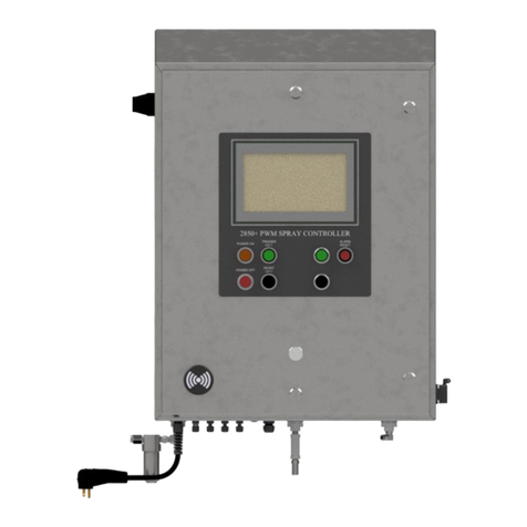
Flow meter panel,
dual-channel version
3.
ADDITIONAL CONNECTIONS
IF APPLICABLE
Main 1
[4A Max.]
Main 2
[4A Max.]
Trig T. Int.
Remote
Setpoint Level Pressure Encoder Flow
Fan/Atm
Air
132
4 65 7 8
1. TRIGGER OR SENSOR
Connect cable to Trig connection that will be
used to start spray sequence. Available triggers
are as follows, the one used should be based
on the customer’s application.
•Trigger cable (for use with customer-supplied
trigger signal)
•Sensors including:
– Object
– Proximity
– Laser (short/long)
– Thru-beam
– Full spectrum color sensor
•Hand-held trigger unit
•Foot switch
2. FAN/ATOMIZING AIR
The Fan/Atm Air electrical connection is used to
actuate the air solenoids in our air control panel.
Connect the cable from the air control panel to
Fan/Atm Air connection on the panel.
3. TRIGGER INTERLOCK
Trigger Interlock controls the state of run/standby
mode. Connect the trigger interlock cable to the T. Int.
connection on the panel.
4. REMOTE SETPOINT (DUTY CYCLE)
Connect the Remote Setpoint cable to the panel.
Once the unit is powered up on the HMI you can set
the duty cycle with a 4-20mA signal to control the
spray nozzles cycle speed.
5. TANK LEVEL SENSOR
Connect the level sensor cable to the Level connec-
tion on the panel. Activate the level sensor from the
Level settings screen on the HMI once the unit is
powered on. When the tank level gets low enough to
trigger the sensor, the unit will display a fault (tank
low) on the screen. Note that the system will not stop
spraying, only show a fault to warn
the operator.
6. LIQUID PRESSURE
Liquid pressure settings require an
active pressure sensor connection
to the 2150+. Connect the pressure
cable to the Pressure connection.
When connected, the input settings
should be calibrated to match the
specifications of your pressure sensor.
7. ENCODER
Encoders are used to read the
speed of a conveyor or machine
shaft. Install the encoder, then
connect the cable to the Encoder
connection on the panel. Activate
the encoder from the HMI in the
Encoder settings screen.
8. FLOW METER
Our Flow Meter Panel will display
flow readings on the HMI. Install the
panel then connect the cable from
the Flow Meter to the Flow connec-
tion on the panel. Set input values to
match the specifications of the flow
meter on the HMI once
it is powered on.
Standard pressure
sensor
Flush-style
pressure sensor
Wheel and pivot
mounted encoder
Hollow shaft
encoder
