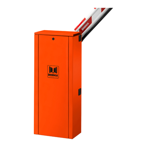
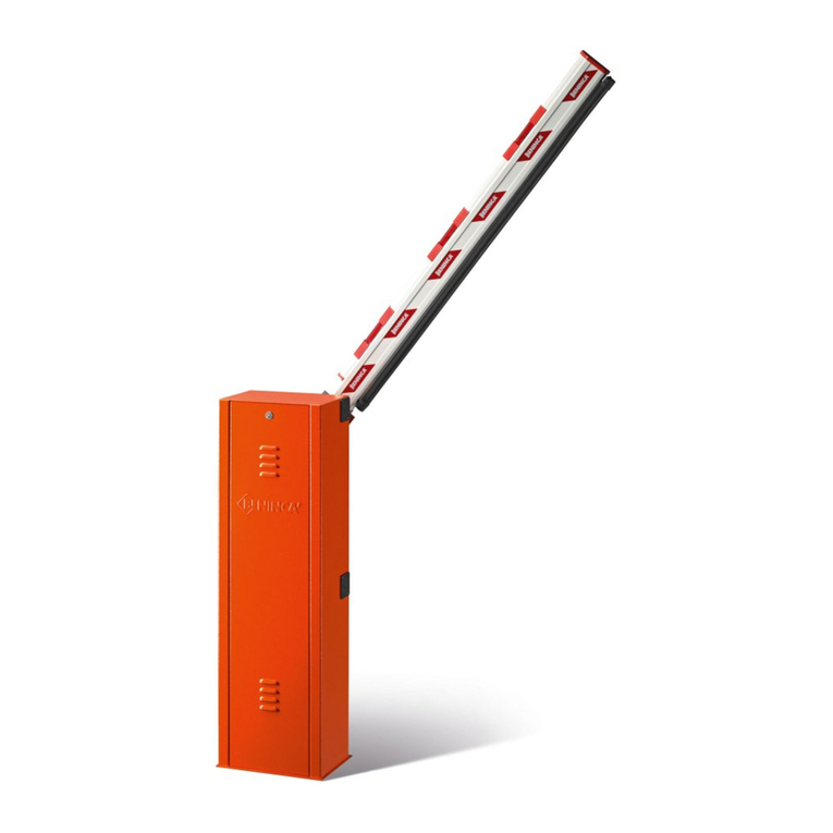
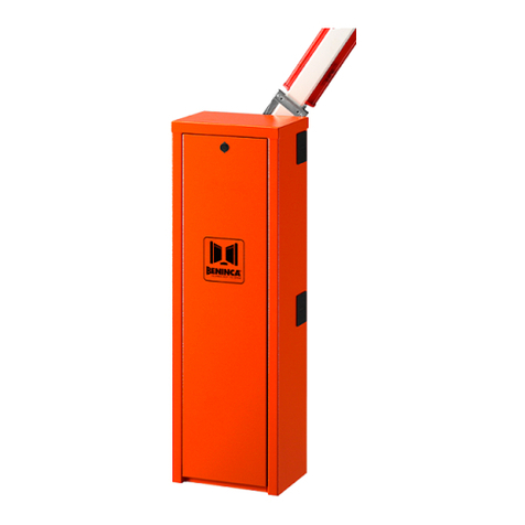
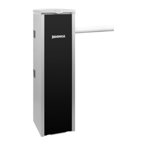
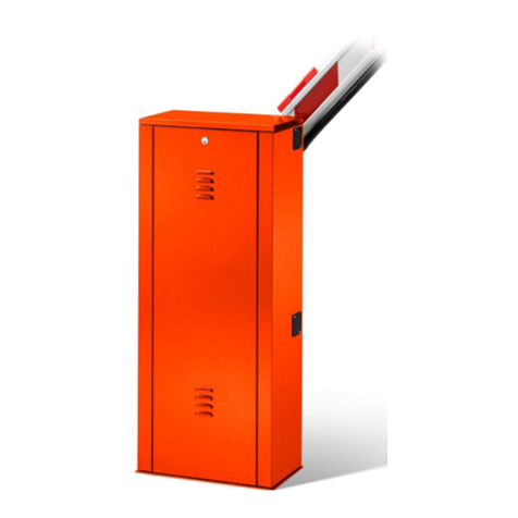
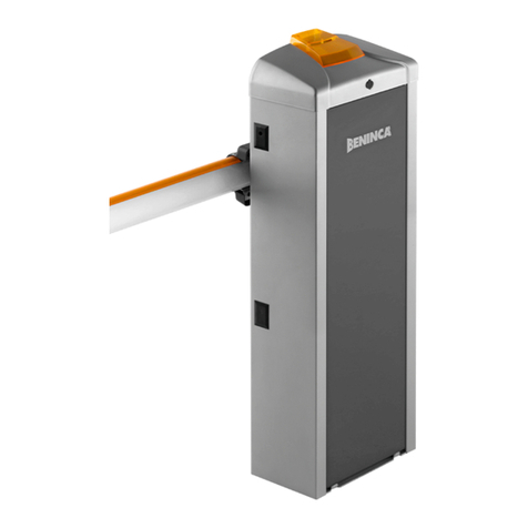
Beninca VE.400 Installer manual

BARRIERE STRADALI
ROAD GATES
STRAßENSPERREN
BARRIÈRES ROUTIÈRES
BARRERAS DE CALLES
VE.400
AUTOMATISMI PER CANCELLI
®
Libro istruzioni e catalogo ricambi
Operating instructions and spare parts catalogue
Betriebsanleitung und Ersatzteilliste
Livret d’instructions et catalogue des pieces de rechange
Libro de instrucciones y catálogo de recambios
UNIONE NAZIONALE COSTRUTTORI
AUTOMATISMI PER CANCELLI, PORTE,
SERRANDE ED AFFINI
L8542220
Rev. 06/99/00
A
Z
I
E
N
D
A
C
E
R
T
I
F
I
C
A
T
A
UNI
EN ISO
9001

2
Dichiarazione CE di conformità Déclaration CE de conformité
EC declaration of confirmity Declaracion CE de conformidad
EG-Konformitatserklarung
Con la presente dichiariamo che il nostro prodotto
We hereby declare that our product
Hiermit erklaren wir, dass unser Produkt
Nous déclarons par la présente que notre produit
Por la presente declaramos que nuestro producto
VE.400
è conforme alle seguenti disposizioni pertinenti:
complies with the following relevant provisions:
folgenden einschlagigen Bestimmungen entspricht:
correspond aux dispositions pertinentes suivantes:
satisface las disposiciones pertinentes siguientes:
Direttiva sulla compatibilità elettromagnetica (89/336/CCE, 93/
68/CEE)
EMC guidelines (89/336/EEC, 93/68/EEC)
EMV-Richtlinie (89/336/EWG, 93/68/EWG)
Directive EMV (89/336/CCE, 93/68/CEE) (Compatibilité élec-
tromagnétique)
Reglamento de compatibilidad electromagnética (89/336/MCE,
93/68/MCE)
Norme armonizzate applicate in particolare:
Applied harmonized standards, in particular:
Angewendete harmonisierte Normen, insbesondere:
Normes harmonisée utilisées, notamment:
Normas armonizadas utilzadas particularmente:
EN 55022, EN 61000-3-2, EN 61000-3-3, EN 50082-1
Norme e specifiche tecniche nazionali applicate in particolare:
Applied national technical standards and specifications, in
particular:
Angewendete nationale Normen und technische
Spezifikationen, insbesondere:
Normes et specifications techniques nationales qui ont été
utilisées, notamment:
Normas y especificaciones técnicas nacionales que se utilizaron
particularmente:
UNI 8612
Data/Firma
Direttiva sulla bassa tensione (73/23/CEE, 93/68/CEE)
Low voltage guidelines (73/23/EEC, 93/68/EEC)
Tiefe Spannung Richtlinie (73/23/EWG, 93/68/EWG)
Directive bas voltage (73/23/CEE, 93/68/CEE)
Reglamento de bajo Voltaje (73/23/MCE, 93/68/MCE)
Norme armonizzate applicate in particolare:
Applied harmonized standards, in particular:
Angewendete harmonisierte Normen, insbesondere:
Normes harmonisée utilisées, notamment:
Normas armonizadas utilzadas particularmente:
EN 60204-1, EN 60335-1
Data/Firma
AUTOMATISMI PER CANCELLI
®
Automatismi Benincà Srl
Via Scamozzi, 3
36030 MONTECCHIO P. VI
ITALIA

3
Introduzione
Ci congratuliamo con Voi per aver scelto la barriera stradale VE.400.
Tutti gli articoli della vasta gamma Benincà sono il frutto di una ventennale esperienza nel settore degli
automatismi e di una continua ricerca di nuovi materiali e di tecnologie all’avanguardia.
Proprio per questo, oggi siamo in grado di offrire dei prodotti estremamente affidabili che, grazie alla loro
potenza, efficacia e durata, soddisfano pienamente le esigenze dell’utente finale.
Tutti i nostri prodotti vengono costruiti in conformità alle norme UNI 8612 e sono coperti da garanzia.
Inoltre, una polizza R.C.prodotti stipulata con primaria compagnia assicurativa copre eventuali danni a cose
o persone causati da difetti di fabbricazione.
Introduction
Thank you for choosing ourVE.400 road gate.
All items in the wide Benincà production range are the result of twenty-years’ experience in the
automatism sector and of continuous research for new materials and advanced technologies.
We are, therefore, in the position to offer highly reliable products that due to their power, effective-
ness and useful life, fully satisfy the final user’s requirements.
All our products are manufactured to the standard UNI 8612 and are covered by warranty.
Possible injury to people or accidents caused by defects in construction are covered by a civil liabil-
ity policy drawn up with one of the major insurance companies.
Einleitung
Wir danken Ihnen dafür, daß Sie sich für die VE.400 Straßensperre entschieden haben.
Alle Produkte der umfangreichen Benincà Produktion sind das Ergebnis der zwanzigjährigen Erfahrungen
im Bereich der Automation und der ständigen Erforschung von neuen Materialien und fortgeschrittenenTech-
nologien.
Aus diesem Grund sind wir heute in der Lage, zuverlässige Produkte anzubieten, die, dank ihren Stärke,
Wirksamkeit und Haltbarkeit, der Anforderungen des Endverbrauchers völlig gerecht werden.
Alle Produkte sind nach UNI Normen 8612 gefertigt und durch Garantie gedeckt.
Eventuelle Personen- oder Sachschäden, die durch Fertigungsfehler verursacht werden können, werden
durch eine der wichtigsten Versicherungsgesellschaften gedeckt.
Introduction
Nous ne pouvons que féliciter d’avoir porté votre choix sur la barrière routièreVE.400.
Vingt années d’expérience dans le secteur des automatismes ainsi que dans le recherche de nou-
veaux matériaux et technologies de pointe,nous ont permis de développer tous les nombreux articles
de la gamme Benincà.
Pour ces raisons, nous sommes en mesure de proposer des produits extrémement fiables et qui
grâce à leurs puissances, performances et longévité, répondent aux exigences des utilisateurs.
Tous nos produits sont construits selon les normes UNI 8612 et sont garantis.
En plus, une police d’assurance responsabilité civile garantie la couverture d’éventuels sinistres à
personnes ou objects causés par les défauts de fabrication.
Introducción
Nos congratulamos con vd. por haber elegido la barrera de calle VE.400.
Todos los artículos de la vasta gama Benincà son el fruto de una veinteañal experiencia en el sector de los
automatismos y de una continua búsqueda de nuevos materiales y de tecnología de vanguardia.
Precisamente por esto, hoy nos encontramos en situación de poder ofrecer productos extremadamente
fiables que, gracias a su potencia, eficacia y duración, satisfacen plenamente las exigencias del usuario final.
Todos nuestros productos están construidos de conformidad con la norma UNI 8612 y están garantizados.
Además, una póliza R.C. productos, estipulada con una de las principales compañías de seguros, cubre
eventuales daños a personas o cosas causados por defectos de fabricación.
4
1. Caratteristiche generali
Di robusta fabbricazione ma tuttavia con un design sobrio e piacevole, le barriere stradali VE.400, grazie al
motore in 24 V DC si prestano al servizio intensivo e continuo.
La regolazione della velocità sia del ciclo che della frenatura, consentono l’ottimizzazione del funzionamen-
to in base all’applicazione ed alle dimensioni dell’asta.
L’installazione è di facile esecuzione come pure la trasformazione da destra a sinistra e viceversa.
Dotata di uno sblocco manuale molto semplice ed intuitivo è predisposta anche per il montaggio di batterie
tampone che ne consentono il funzionamento anche in mancanza dell’alimentazione di linea.
L’asta in alluminio anodizzato è predisposta per l’applicazione di tutti gli accessori, dei dispositivi di segnala-
zione e di sicurezza; quest’ultima è anche assicurata da un sensore amperometrico che interrompe il movi-
mento al minimo contatto con un eventuale ostacolo.
1. General features
TheVE.400 road gates, stout in construction and simply but nicely designed, are suitable to be used
intensively and continuosly thanks to their 24V DC motor.
Speed adjustment, both during the cycle and the braking phase, makes the operation optimization
possible depending on the application and rod dimensions.
Installation is easy as well as the transformation from right to left and viceversa.
With its simple manual release it is also ready to accept buffer batteries which permit the gate run-
ning also in case there is no electricity. To the anodised aluminium rod it is possible to apply all
accessories, warning and safety devices; safety is also granted by the amperometric sensor which
interrupts the movement as soon as there’s a min. contact with a possible obstacle.
1. Allgemeine Eigenshaften
Die StraßensperrenVE.400 sind kräftig gebaut, von nüchterner, doch gefälliger Linie und eignen sich dank
ihrem 24 V Gleichstrommotor zum Dauereinsatz.
Die Geschwindigkeitsregulierung des Arbeitskreislaufes sowie der Bremsung ermöglicht besten Betrieb
aufgrund der Stangenanbringung und -maße.
Die Anbringung der Sperre und ihre Umstellung von rechter auf linke sind leicht. Sie ist mit einer sehr
einfachen und schnellansprechenden Handfreigabevorrichtung ausgestattet und ist gleichfalls auf die
Anbringung von Pufferbatterien eingerichtet, die ihren Betrieb auch bei Ausfall des Leistungsstromes zulas-
sen.
Die Stange aus eloxiertem Aluminium ist auf die Anbringung allen Zubehörs und der Signal- und
Sichereitsvorrichtungen eingestellt;die Sichereit wird auch von einem Strommeßfühler gewahrleistet, der die
Bewegung bei der geringsten Berührung mit einem Hindernis unterbricht.
1. Caractéristiques générales
De fabrication solide avec un design sobre et plaisant, les barrières routièresVE.400, grâce au mo-
teur en 24V DC se prêtent au service intensif et continu.
Le réglage de la vitesse aussi bien du cycle que du freinage, permet l’optimisation du fonctionne-
ment selon l’application et les dimensions de la barre.
L’installation est facile d’exécution comme également la transformation de droite à gauche et vice
versa.
Équipées d’un déblocage manuel très simple et intuitif, elles sont prédisposées aussi pour le mon-
tage de batteries tampon qui permettent leur fonctionnement même en cas de manque d’alimentation
de la ligne.
La barre en aluminium anodisé est prédisposée pour l’application de tous les accessoires, des dis-
positifs de signalisation et de sécurité. Cette dernière est assurée également par un senseur de cou-
rant qui interrompt le mouvement au moindre contact avec un obstacle éventuel.

5
1. Características generales
De robusta fabricación pero además con un diseño sobrio y agradable, las barreras de calles VE.400,
gracias al motor en 24 V DC se prestan al servicio intensivo y continuo.
La regulación de la velocidad tanto en ciclo como en la frenada, permite la optimatización del funcionamien-
to en base a la aplicación y a las dimensiones del asta.
La instalación es de fácil ejecución como así mismo la transformación de derecha a izquierda y viceversa.
Provista de un desbloqueo manual muy simple e intuitivo, está predispuesta también para el montaje de
baterías herméticas que nos permiten el funcionamiento también en ausencia de alimentación de línea.
El asta de aluminio anodizado está predispuesta para la aplicación de todos los accesorios y de los dispo-
sitivos de señalización y de seguridad;ésta última está también asegurada por un sensor amperométrico que
interrumpe el movimiento al mínimo contacto con un eventual obstáculo.

6
Alimentazione Feed
Speisung Alimentation
Potenza motore Motor rating
Motor Leistung Puissance du moteur
Assorbimento motore Motor absorption
Motor Verbrauch Absorption du moteur
Coppia Torque
Drehmoment Couple
Rapporto di riduzione Reduction ratio
Untersetzungsverhältnis Rapport de réduction
Classe isolamento Insulation class
Isolierklasse Classe d’isolement
Temp. funzionamento Working temp.
Betriebstemperatur Temper. fonctionnement
Tempo apertura Opening time
Öffnungszeit
Temps d’ouverture
Lubrificazione Lubrication
Schmierung Lubrification
Peso Weight
Gewicht Poids
Dimensioni Dimensions
Masse Dimensions
V
W
A
Nm
°C
sec
Kg
mm
230
Dati tecnici Technical data Technische Daten Donnees technique VE.400
70
4.6
210
0,005
Y
-20°/+70°
2÷7
61
Grasso permanente
Permanent grease
Langlebiges Fett
Graisse permanent
Grasa permanente
Alimentazione motore
Alimentación
Potencia motor
Absorción motor
Par
Relación de reducción
Clase de aislamiento
Temp. de funcionamiento
Tiempo de apertura
Lubrificación
Peso
Dimensiones
Datos técnicos
Alimentación motorMotor feed
Motor Speisung Alimentation du moteur
V24
320x220xH1060
Riferimento targhetta sull’azionamento
See operation plate
Siehe Schildchen auf der Motor-Gruppe
Voir la plaque sur le motoréducteur
Referencia en la placa sobre el accionamiento

7
2. Scelta della molla
2. Spring selection
2.Wahl der Feder
2. Selection de le ressort
2. Selección del muelle
Con accessori: VE.AM-VE.L500
With accessories: VE.AM-VE.L500
Mit Zubehör: VE.AM-VE.L500
Avec accessoires: VE.AM-VE.L500
Con accessorios: VE.AM-VE.L500
2.0m 2.5 3.0 3.5 4.0 4.5 5.0
Con accessori: VE.AM-VE.RAST-VE.L500-SC.RES
With accessories: VE.AM-VE.RAST-VE.L500-SC.RES
Mit Zubehör: VE.AM-VE.RAST-VE.L500-SC.RES
Avec accessoires: VE.AM-VE.RAST-VE.L500-SC.RES
Con accessorios: VE.AM-VE.RAST-VE.L500-SC.RES
Con accessori: VE.AM-VE.L500-SC.RES
With accessories: VE.AM-VE.L500-SC.RES
Mit Zubehör: VE.AM-VE.L500-SC.RES
Avec accessoires: VE.AM-VE.L500-SC.RES
Con accessorios: VE.AM-VE.L500-SC.RES
Molla gialla
Yellow spring
Gelbe Feder
Ressort jeune
Muella amarilla
Molla neutra
Neutral spring
Neutre Feder
Ressort neutre
Muella neutra
Molla bianca
White spring
Weiße Feder
Ressort blanc
Muella bianca
Scelta della molla - Spring selection -
Wahl der Feder
Selection de le ressort -
Selección del muelle
N.B.: Per le aste giuntate o articolate fare sempre riferimento alla presente tabella. Le VE.400 standard hanno 1 molla bianca.
P.N. For coupled or articulated rods, refer always to present table. Standard VE.400 are equipped with 1 white spring.
Achtung: für gekoppelte oder gelenkige Stangen, bitte die Tabelle beachten. Die VE.400 standard haben eine weiße Feder.
N.B. Pour les barres jointées ou articulées se référer à le présent tableau. Les VE.400 standard ont un ressort blanc.
NOTA: Para el asta empalmada o articulada hacer siempre referencia a la presente tabla. Las VE.400 estándar han 1 muella bianca
Lunghezza barriera - Barrier length -
Sperrenlänge
Longeur barrière -
Longitud de la barra
VE.400 / VE.400I

8
3. Posa della piastra di fondazione
3. Foundation plate positioning
3. Montage der Fundamentplatte
3. Mise en place de la plaque de fondation
3. Posicionamiento de la placa de alimentación
330
150
240
260
Rosetta Ø13x24 UNI 6592.
Washer Ø13x24 UNI 6592.
Unterlegscheibe Ø13x24 UNI 6592.
Rondelle Ø13x24 UNI 6592.
Arandela Ø13x24 UNI 6592.
Dado M12 UNI 5588.
Nut M12 UNI 5588.
Mutter M12 UNI 5588.
Ecrou M12 UNI 5588.
Tuerca M12 UNI 5588.
Mettere in piano la piastra tramite livella.
Lay flat through the level.
Mittels Grundwaage ausgleichen.
Mettre en niveau avec la nivelle.
Poner plana la placa con el nivel.
Livella.
Level.
Grundwaage.
Nivelle.
Nivel.
Foro per passaggio cavi.
Cables hole.
Bohrung für Kabeleinlaß.
Trou pour le passage des câbles.
Agujero para sacar cables.
Piastra di fondazione.
Foundation plate.
Fundamentplatte.
Plaque de fondation.
Placa de cimentación.
Staffa a cementare.
Flask to be cemented.
Bügel zu zementieren.
Étrier à cimenter.
Pletina para hormigonar.
Vite M12x50 UNI 5739.
Screw M12x50 UNI 5739.
Schraube M12x50 UNI 5739.
Vis M12x50 UNI 5739.
Tornillo M12x50 UNI 5739.

9
4. Perno d’uscita e fissaggio asta
4. Outlet journal and rod fixing
4. Ausgangszapfen und Sperrenbefestigung
4. Pivot de sortie et fixation de la barre
4. Perno de salida y fijación del asta
220
320 1060
Porta.
Door.
Tür.
Porte.
Puerta.
Leva.
Rod.
Hebel.
Levier.
Palanca.
Piastra.
Plate.
Platte.
Plaque.
Placa.
Asta VE.200S/500S.
Rod VE.200S/500S.
Sperre VE.200S/500S.
Barre VE.200S/500S.
Varilla VE.200S/500S.
Supporto.
Support.
Lagerung.
Support.
Soporte.
Colonna.
Column.
Schenkel.
Montante.
Armario. Lampeggianti VE.L200/500.
VE.L200/500 flash-lights.
Blinker VE.L200/500.
Clignotants VE.L200/500.
Relampagueadores VE.L200/500.
Supporto.
Support.
Stütze .
Support.
Soporte.
Vite M14x30 UNI 5933.
Screw M14x30 UNI 5933.
Schraube M14x30 UNI 5933.
Vis M14x30 UNI 5933.
Tornillo M14x30 UNI 5933.
Vite M8x16 UNI 5931.
Screw M8x16 UNI 5931.
Schraube M8x16 UNI 5931.
Vis M8x16 UNI 5931.
Tornillo M8x16 UNI 5931.
Rosetta Ø8.4x17 UNI 6592.
Washer Ø8.4x17 UNI 6592.
Unterlegscheibe Ø8.4x17 UNI 6592.
Rondelle Ø8.4x17 UNI 6592.
Arandela Ø8.4x17 UNI 6592.
V ring (V 60A).
V ring (V 60A).
V ring (V 60A).
V ring (V 60A).
Retén (V 60A).
Staffa.
Flask.
Bügel.
Étrier.
Pletina.

10
G
L
M
D
V
Fig.1
Scheda logica.
Logical card.
Logikkarte.
Carte logique.
Tarjeta lógica.
Posizione 1.
Position 1.
Stellung 1.
Position 1.
Posición 1.
Posizione 2.
Position 2.
Stellung 2.
Position 2.
Posición 2.
9686124
Testa di biella maschio M12 (9686125).
Spheric head M12 (9686125).
Kugelkopf M12 (9686125).
Tête sphérique M12 (9686125).
Cabeza de biela macho M12 (9686125).
Dado M12 UNI 5588.
Nut M12 UNI 5588.
Mutter M12 UNI 5588.
Ecrou M12 UNI 5588.
Tuerca M12 UNI 5588.

11
5. Predisposizione barriera destra-sinistra
5.1 Viene definita destra una barriera che, vista dal lato porta, va ad impegnare il passaggio sul lato destro;
viceversa è sinistra.
5.2 Nella fig. 1 è rappresentata una barriera destra, per renderla sinistra procedere come segue:
• assicurarsi che la molla M sia scarica (posizionata come in figura)
• levare la molla e fissarla sulla posizione 1 mediante la vite V ed i dadi D.
• svitare il grano G e spostare la leva L ed il grano G sulla posizione 2.
5. Right-left gate pre-arrangement
5.1 A road gate is called right when looking at it from the door side, it engages the way on the right
side; viceversa it is called left.
5.2 Fig. 1 represents a right gate; to transform it into left proceed as follows:
• make sure the spring M is released (positioned as per fig.).
• remove the spring and fix it in position 1 through the screw V and the nuts D
• untighten the grain G and move the lever L and the grain G to position 2.
5. Einrichtung der Sperre auf rechte oder Linke Stellung
5.1 Als rechte wird eine Sperre bezeichnet, die, von der Tür gesehen, die Durchfahrt auf der rechten Seite
verhindert. Im umgekehrten Falle ist es eine linke Sperre.
5.2 Auf Abbildung 1 sehen Sie eine rechte Sperre;um sie in eine linke zu verwandeln, gehen Sie wie folgt vor:
• Vergewissern Sie sich, daß die ungeladene Feder M wie auf der Abbildung ausgerichtet ist.
• Nehmen Sie die Feder heraus und befestigen Sie sie mittels Schraube V und Muttern D in Stellung 1.
• Stift G abschrauben und Hebel L und Stift G auf 2 stellen.
5. Prédisposition Barriere Droite-Gauche
5.1 On définit comme droite une barrière qui, vue du côté porte couvre le passage sur le côté droit et
vice versa pour la gauche.
5.2 Sur la Fig. 1 une barrière droite est représentée, pour la rendre gauche procéder comme suit :
• vous assurer que le ressort M soit déchargé (positionné comme sur la figure);
• enlever le ressort et le fixer sur la position 1 au moyen de la vis V et des écrous D;
• dévisser l’ergot G et déplacer le levier L et l’ergot G sur la position 2.
5. Predisposición barrera derecha-izquierda
5.1 Se define derecha una barrera que, vista desde el lado de la puerta, va a impedir el paso sobre el lado
derecho; viceversa es izquierda.
5.2 En la fig.1 está representada una barrera derecha, para volverla izquierda proceder como sigue:
• Asegurarse que el muelle M esté destensado (posicionando como en la figura)
• Levantar el muelle y fijarlo sobre la posición 1 mediante el tornillo V y las tuercas D.
• Desatornillar el grano G y colocar la leva L y el grano G sobre la posición 2.

12
D
≈45°
Fig.2
Molla concorrente.
Return spring.
Entgegengesetzte Feder.
Contre ressort.
Muelle compensador.
Fermo meccanico apertura.
Mechanical stop for opening.
Mech. Halt Öffnung.
Arrêt mécanique ouverture.
Tope mecánico apertura.
Con il motoriduttore sbloccato:
• l’asta tende a chiudere?
tensionare la molla avvitando il dado D.
• l’asta tende ad aprire?
scaricare la molla svitando il dado D.
With the ratio motor released:
• does the rod try to close?Tension the spring by
tightening the nut D.
• does the rod try to open? Release the spring by
unscrewing the nut D.
Bei freigegebenem Getriebemotor:
• neigt die Stange zum Schließen?
Feder durch Anschrauben der Mutter D spannen.
• neigt die Stange zum Öffnen?
Feder durch Abschrauben der Mutter D entladen.
Avec le moto réducteur débloqué :
• la barre tend à se fermer ?
tendre le ressort en vissant
l’écrou D.
• la barre tend à s’ouvrir
décharger le ressort en dévissant
l’écrou D.
Con el motor desbloqueado:
• el asta tiende a cerrar?
tensar el muelle enroscando las tuercas D.
• el asta tiende a abrir?
destensar el muelle desenroscando las tuercas D.
Scheda logica.
Logical card.
Logikkarte.
Carte logique.
Tarjeta lógica.
Leva di sblocco.
Release lever.
Freigabehebel.
Levier de déblocage.
Palanca de desbloqueo.
Sblocca.
Unblock.
Freigabe.
Déblocage.
Desbloquea.
Fermo meccanico chiusura.
Mechanical stop for closing.
Mech. Halt Schließung.
Arrêt mécanique fermeture.
Tope mecánico cierre.
Bandierine azionamento micro.
Micro operation flag.
Fähnchen zum Betätigen des Mikroschalters.
Pavillons d’actionnement micros.
Balancines accionamiento micro.

13
6. Equilibratura (fig. 2)
Per un buon funzionamento della barriera è fondamentale che l’asta sia opportunamente equilibrata dal-
l’azione della molla concorrente.
Per verificare ciò agire come segue:
• Sbloccare meccanicamente la barriera tramite la leva di sblocco.
• Portare l’asta in chiusura e lasciarla; questa si dovrà posizionare a circa 45°.
Ripetere l’operazione portando l’asta in apertura.
Se l’equilibratura non corrisponde alle caratteristiche sopra menzionate, agire sul carico molla tramite il
dado D.
6. Balancing (fig. 2)
For a good road gate operation it is important that the rod is well balanced through the spring action,
and to check it is so proceed as follows:
• release mechanically the road gate through the release lever.
• start closing the rod and leave it; the rod will have to be positioned at about 45°.
Repeat the operation by moving the rod towards the opening position.
If the balancing is not within the limits above mentioned act on the spring load through the nut D.
6. Auswuchtung (Bild 2)
Zum guten Betrieb der Sperre ist es von grundlegender Bedeutung, daß die Stange durch die Wirkung der
entgegengesetzten Feder richtig ausgerichtet wird. Um das zu prüfen, tun Sie folgendes:
• Sperre durch Freigabehebel mechanisch freigeben,
• Stange in Schließstellung bringen und loslassen. Sie soll sich auf etwa 45
°
stellen.
Den Vorgang wiederholen, indem Sie die Stange in Öffnungsstellung bringen.
Wenn die Auswuchtung den oben genannten Merkmalen nicht entspricht, wirke man über Mutter D auf die
Federladung ein.
6. Équilibrage (fig. 2)
Pour un bon fonctionnement de la barrière il est fondamental que la barre soit opportunément équi-
librée par l’action du contre ressort.
Pour vérifier ceci agir comme suit :
• débloquer mécaniquement la barrière au moyen du levier de déblocage ;
• mettre la barre sur la fermeture et la laisser ; celle-ci devra se positionner à environ 45
°
.
Répéter l’opération en mettant la barre sur l’ouverture.
Si l’équilibrage ne correspond pas aux caractéristiques ci-dessus mentionnées, agir sur la charge
du ressort par l’intermédiaire de l’écrou D.
6. Equilibrado (fig. 2)
Para un buen funcionamiento de la barrera es fundamental que el asta esté correctamente equilibrada por
la acción del muelle compensador.
Para comprobarlo operar como sigue:
• Desbloquear mecánicamente la barrera mediante la leva de desbloqueo.
• Poner el asta cerrada y dejarla; ésta se deberá posicionar a aproximadamente 45°.
Repetir la operación poniendo el asta abierta.
Si el equilibrado no corresponde a la característica arriba mencionada, operar sobre el tensado del muelle
mediante las tuercas D.

14
Posticipa l’azione frenante.
Posticipate the braking action.
Verzögert das Bremsen.
Retarde l’action freinante.
Retrasa la acción de frenado.
Posticipa l’azione frenante.
Posticipate the braking action.
Verzögert das Bremsen.
Retarde l’action freinante.
Retrasa la acción de frenado.
Anticipa l’azione frenante.
Anticipate the braking action.
Beschleunigt das Bremsen.
Anticipe l’action freinante.
Anticipa la acción de frenado.
Anticipa l’azione frenante.
Anticipate the braking action.
Beschleunigt das Bremsen.
Anticipe l’action freinante.
Anticipa la acción de frenado.
Fig.3
Bandierina apertura.
Opening flag.
Fähnchen zur Öffnung.
Pavillon d’ouverture.
Banlancín de apertura.
Bandierina chiusura.
Closing flag.
Fähnchen zur Schließung.
Pavillon de fermeture.
Banlancín de cierre.
A
B
Spazio di frenatura.
Braking space.
Bremsraum.
Espace de freinage.
Espacio de frenado.
Punto di intervento del finecorsa meccanico in apertura.
Intervention point of the opening mechanical limit stop.
Wirkungsstelle des mechanischen Endschalters beim Öffnen.
Point d’intervention du fin de course mécanique en ouverture.
Punto de intervención del final de carrera mecánico en apertura.
Punto di intervento del finecorsa meccanico in chiusura.
Intervention point of the closing mechanical limit stop.
Wirkungsstelle des mechanischen Endschalters beim Schließen.
Point d’intervention du fin de course mécanique en fermeture
Punto de intervención del final de carrera mecánico en cierre.
Spazio di frenatura.
Braking space.
Bremsraum.
Espace de freinage.
Espacio de frenado.
Ciclo di lavoro della sbarra.
Road gate working cycle.
Arbeitskreislauf des Sperrbaumes.
Cycle de travail de la barriere.
Ciclo de trabajo de la barrera.
Fotodispositivi.
Photo-electric cells.
Fotozellen.
Cellules photoélectriques.
Fotodispositivos.

15
7. Movimenti e tempi di lavoro di una sbarra (fig. 3)
La sbarra parte dal punto ”A” e arriva fino all’intervento del finecorsa in chiusura con una velocità che viene
impostata con il trimmer velocità di ciclo presente sulla logica della centralina.
Dall’intervento del finecorsa inizia il ciclo di frenatura. La sbarra percorre lo spazio di frenatura in un tempo
fisso pari a circa 6 sec. e ad una velocità regolabile con il trimmer velocità di frenatura presente sulla scheda
logica della centralina.La sbarra arriva così al punto ”B” completando il movimento di chiusura.
Per il ciclo di apertura valgono le stesse considerazioni.
Regolare quindi finecorsa, camme e i trimmer sulla scheda logica della centralina tenendo presente anche
queste considerazioni.
7. Movement and working times of a road gate (fig. 3)
The gate moves from “A” to the closing limit stop intervention at a speed which is set through the
cycle speed trimmer placed on the gearcase logic card.
With the limit stop intervention starts the braking cycle.The road gate covers the braking area in 6
seconds approx which is a fixed time and at a speed which can be adjusted through the braking speed
trimmer placed on the gear case logical card.
The gate reaches this way point “B” and completes the closing movement.
Same considerations are valid for the opening cycle.
Adjust now the limit stops, the cams and the trimmer on the gearcase logical card by paying atten-
tion also to these considerations.
7. Bewegungen und Arbeitszeiten eines Sperrbaumes (Bild 3)
Der Sperrbaum geht von Stelle A aus und kommt an der Wirkungsstelle des Schließendschalters mit einer
Gescwindigkeitan, die mit dem auf der Logikkarte des Schaltschrankes befindlichenGeschwindigkeitstrimmer
eingestellt worden ist.
Mit der Einwirkung des Endschalters beginnt der Bremskreislauf. Der Sperrbaum durchläuft den Brems-
raum in einer festen Zeit gleich etwa 6 Sekunden und mit einer Geschwindigkeit, die mit dem
Bremsgeschwindigkeitstrimmer auf der Logikkarte des Schaltschrankes reguliert werden kann. Der Sperr-
baum erreicht so die Stelle B und vollzieht die Schließbewegung.
Das gleiche gilt für den Öffnungskreislauf. Man reguliere dann Endschalter, Nocken und Trimmer auf der
Logikkarte und bedenke dabei diese Hinweise.
7. Déplacements et temps de travail d’une barrière (fig. 3)
La barrière part du point“ A“ et arrive jusqu’à l’intervention du fin de course en fermeture avec une
vitesse qui est programmée avec le trimmer de vitesse de cycle présent sur la logique de la centrale.
Le cycle de freinage commence à partir de l’intervention du fin de course, la barrière parcourt l’es-
pace de freinage en un temps fixe égal à environ 6 sec. et à une vitesse réglable avec le trimmer de
vitesse de freinage présent sur la carte logique de la centrale. La barrière arrive ainsi au point“ B“ en
complétant le mouvement de fermeture.
Pour le cycle d’ouverture les mêmes considérations sont applicables.
Régler donc les fins de course, les cames, et les trimmers sur la carte logique de la centrale en
tenant compte aussi de ces considérations.
7. Movimientos y tiempos de trabajo de una barrera (fig. 3)
La barrera parte del punto “A” y llega hasta la intervención del final de carrera de cierre con una velocidad
que está impuesta con el potenciómetro de velocidad de ciclo presente sobre la lógica de la centralita.
A la intervención del final de carrera inicia el ciclo de frenado.La barrera recorre el espacio de frenado en un
tiempo fijo de aproximadamente 6 segundos y a una velocidad regulable con el potenciómetro de velocidad
de frenado presente sobre la tarjeta lógica de la centralita. La barrera llega así al punto “B” completando el
movimiento de cierre.
Para el ciclo de apertura son válidas las mismas consideraciónes.

16
Regular a continuación finales de carrera, balancines y los potenciómetros sobre la tarjeta lógica de la
centralita teniendo en cuenta también estas consideraciones.
ATTENZIONE
ATTENZIONEATTENZIONE
La polizza RC prodotti, che risponde di eventuali danni a cose o persone causati da difetti di fabbricazione,
richiede la conformità dell’impianto alla normativa UNI 8612 e l’utilizzo di accessori originali Benincà.
CAUTION
CAUTIONCAUTION
The civil liability policy, which covers possible injuries to people or accidents caused by defects in
construction,requires the system to be to standard UNI 8612 and to use original Benincà accessories.
BITTE BEACHTEN
BITTE BEACHTENBITTE BEACHTEN
Die Versicherung deckt nur Personen- oder Sachschäden, die durch Fertigungsfehler verursacht werden
und gilt nur bei Einsatz von Benincà Original-Ersatzteilen und wenn die Anlage der UNI-Normen 8612 ent-
spricht.
ATTENTION
ATTENTIONATTENTION
Pour que la police d’assurance R.C.réponde à d’eventuels sinistres causés à choses ou personnes,
en cas de défauts de fabrication,il faut que le montage soit réalisé suivant les normes UNI 8612 et que
soient utilisés des accessoires Benincà.
ATENCION
ATENCIONATENCION
La póliza RC productos, que responde de eventuales daños a personas o cosas causados por defectos de
fabricacion, requiere la conformidad de la instalación según la normativa UNI 8612 y la utilización de acceso-
rios originales Benincà.

17
8. Installazione
Effettuare tutti i collegamenti ai pulsanti, ai fotodispositivi (facendo attenzione alla polarità dell’alimentazio-
ne). Ponticellare verso il comune (morsetto n°5) tutte le linee N.C. non utilizzate (es.fotodispositivi, pulsante
di stop). Se vengono installate più coppie di fotodispositivi i contatti devono essere posti in SERIE.
Collegare alle rispettive uscite spia cancello aperto, elettroserratura, lampeggiatori e motore.
Le uscite inutilizzate devono essere isolate.
Posizionare tutti i trimmer della scheda logica a metà corsa.
Selezionare la giusta tensione per l’elettroserratura.
Escludere per il momento la richiusura automatica.
Collegare la batteria, se prevista, facendo attenzione alla polarità.
A questo punto si devono illuminare i led ”FOTO”, ”STOP”, ”F.AP” e ”F.CH”. Se ciò non avviene controllare
che i rispettivi collegamenti siano corretti.
Muovendo la sbarra a mano, verificare che poco prima della completa apertura si spenga il led ”F.AP”e che
poco prima della completa chiusura si spenga il led ”F.CH”; indi riposizionare la sbarra a metà corsa (45°) e
disinserire il dispositivo di sblocco manuale.
Prima di ogni intervento sull’impianto scollegare la linea 230 V AC e le batterie.
Azionare quindi il pulsante di apertura: se l’automazione si muove in chiusura premere il pulsante di stop,
scollegare i 230 V AC e la batteria, indi invertire i collegamenti del motore.Ricollegare la batteria e 230 V AC
e premere il pulsante di apertura; effettuare la regolazione della velocità di lavoro mediante il trimmer ”B”,
secondo le norme vigenti, e attendere l’arrivo al finecorsa.
Regolare l’intervento del circuito di frenatura, posizionando opportunamente la camma sul finecorsa e rego-
lando il trimmer ”C” per un arresto dolce.
Premere il pulsante di chiusura; effettuare la regolazione di coppia secondo le norme vigenti mediante il
trimmer ”A” in modo tale che, con uno sforzo moderato, si riesca ad arrestare il movimento; in ogni caso
attenersi alle norme.
N.B.: agire sui trimmer molto lentamente per non provocare l’arresto dell’automazione.
Verificare quindi il funzionamento delle sicurezze tenendo presente che:
• premendo lo stop in qualsiasi condizione, l’impianto si arresta ed attende un comando;
• l’intervento dei fotodispositivi in chiusura provoca una riapertura completa istantanea, mentre in
apertura non vi è alcun intervento;
• il montaggio dei microinterruttori di finecorsa è indispensabile per un corretto funzionamento del
dispositivo.
N.B.: ogni qualvolta la somma delle manovre eseguite crei confusione, staccare per qualche secondo la
batteria e la rete, quindi ridare tensione e proseguire le prove.
N.B.:in assenza di rete 230V AC, con batterie completamente cariche, è possibile effettuare da 10 a 30 cicli
di manovra completi, a seconda del peso dell’automazione.
N.B.: se possibile evitare le regolazioni estreme dei trimmer di velocità e potenza.
N.B.: La sezione minima dei cavi del motore dovrà essere di:
• 1.5 mm2per lunghezze fino a metri 1
• 2.5 mm2per lunghezze fino a metri 3
• 4.0 mm2per lunghezze fino a metri 6

18
8. Installation
Carry out all the push-buttons and photo-electric cells connections (pay attention to the feed polar-
ity). Bond to the common contact (terminal no. 5) all the N.C. lines not used (for instance the photo-
electric cells,the stop push-button).If more than one pair of photo-electric cells are installed,contacts
must be placed in series.
Connect the open gate pilot light, the electric lock, the flash-lights and the motor to their outlets.
Isolate the outlets not used.
Position all the trimmers of the logical card in half-stroke position.
Select the right tension for the electric lock.
Exclude temporarily the automatic re-closure.
Connect the battery, paying attention to the polarity.
At this stage the “PHOTO” - “STOP” - “OP.F” and “CL.F” led must light up. If this does not happen,
check that all these connections are correct. By moving the gate manually, check that just before the
complete opening, the led “OP.B” turns off and that just before the complete closure the led “CL.B”
turns off; then place the gate at half of its stroke (45°) and disconnect the manual release device.
Before any intervention on the system disconnect the 230 V AC line and the batteries.
Operate now the opening push-button: if the automation starts closing, press the stop push-button,
disconnect the 230V AC and the battery and reverse the motor cables. Reconnect the battery and the
230V AC and press the opening push-button;adjust the working speed through the trimmer B accord-
ing to standard in force and wait for the limit stop arrival.
Adjust the braking circuit intervention by positioning correctly the cam onto the limit stops and
adjusting the trimmer C for a smooth stop.
Press the closing push-button; adjust now the torque according to standard in force through the
trimmer A so as to stop the movement with a moderate effort; keep to the standard in any case.
P.N.: operate slowly onto the trimmer to avoid that the automation stops. Check the safety catches
operation and take into consideration following points:
• any time STOP is pressed, the system stops and wait for a control;
• the photo-electric cells intervention during the closing phase causes a complete instantaneous
re-opening, whereas there is no intervention during the opening phase.
• The limit stop micro-switches have to be installed for a correct device operation.
P.N. Any time the addition of the carried out motions create some confusion, disconnect the battery
and the network for a few seconds, then apply voltage and proceed with the tests.
P.N. If there is no 230V AC network but batteries are totally loaded, it is possible to carry out 10 to 30
complete motion cycles depending on the automation weight.
P.N. Please avoid if possible extreme adjustments of speed and rating trimmers.
P.N.The min. section of the motor cables will have to be
• 1,5 sq.mm for lengths up to 1 m.
• 2,5 sq.mm for lengths up to 3 m.
• 4,0 sq.mm for lengths up to 6 m.

19
8. Anbringung
Alle Anschlüsse an Drucktasten und Fotozellen vornehmen und die Zufuhrpole beachten. Zum gemeinsa-
men Kontakt (Klemme 5) alle nicht benutzten NC-Leitungen mit Brücken versehen (z.B. Fotozellen, Halt-
knopf).Werden mehrere Paar Fotozellen angebracht, müssen die Kontakte in serie geschaltet werden.
Schließen Sie Kontrollicht für offenes Gittertor, Elektroschloß, Blinker und Motor an die jeweiligen Ausgänge
an.
Die unbenutzten Ausgänge müssen isoliert werden.
Alle Trimmer der Logikkarte auf halben Hub stellen.
Die richtige Spannung für das Elektroschloß wählen.
Einstweilen die automatische Schließung abschalten.
Batterie, wenn vorgesehen, anschließen und Pole beachten.
Nun müssen die LED FOTO , STOP, F.AP (F. offen) und F.CH (F. geschl.) aufleuchten.
Geschieht das nicht, prüfen Sie, ob die jeweiligen Anschlüsse stimmen.
Während Sie die Absperrung mit der Hand bewegen, prüfen Sie, ob kurz vor dem völligen Öffnen das LED
FAP erlischt und ob kurz vor dem völligen Schließen das LED FCH erlischt;dann stellen Sie die Sperre wieder
auf halben Hub (45
°
) und schalten die Handfreigabevorrichtung vorsichtig aus.
Vor jedem Eingriff an der Anlage nehmen Sie die 230-VAC-Leitung und die Batterien vom Netz.
Drücken Sie nun auf den Öffnungsknopf: wenn die Automation sich in Schließung bewegt, Haltknopf drük-
ken, 230VAC und Batterie abschalten und dann die Motoranschlüsse umkehren.Batterie und 230VAC wieder
anschließen und Öffnungsknopf drücken.Die Arbeitsgeschwindigkeit mittelsTrimmer B gemäs den geltenden
Vorschriften regulieren und das Eintreffen am Endschalter abwarten.
Den Eingriff des Bremskreises regulieren, indem Sie die Nocke auf die Endschalter ausrichten und den
Trimmer C für einen sanften halt regulieren.
Schließknopf drücken, Drehmoment nach den geltenden Vorschriften regulieren (mit Trimmer A), so daß
man die Bewegung mit mäßiger Anstrengung anhalten kann.In jedem Fall halte man sich an dieVorschriften.
Zu beachten:Trimmer sehr langsam betätigen, um nicht den Stillstand der Automation hervorzurufen.Dann
den Betrieb der Sichereitsvorrichtungen prüfen und bedenken, daß
• wenn mann in jeglichem Zustand STOP drückt, die Anlage stehenbleibt und einen Befehl erwartet,
• der Eingriff der Fotozellen beim Schließen ein sofortiges Wiederschließen hervorruft, während beim
Öffnen kein Engriff stattfindet
• die Anbringung der Mikroendschalter für den richtigen Betrieb des Gerätes unentbehrlich ist.
Jedesmal wenn die Summe der ausgeführten Bewegungen verwirrend wird, nehmen Sie die Batterie einige
Sekunden vom Netz, geben dann wieder Spannung und setzen die Versuche fort.
Bei Fehlen des Netzes von 230 VAC und bei ganz vollen Batterien ist es möglich, 10 bis 30 vollständige
Schaltkreisläufe auszuführen, je nach dem Gewicht der Automation.
Wenn möglich vermeide man äußerste Regulierungen des Geschwindigkeits- und Stromleistungstrimmers.
Es ist wichtig, die zwei Motoren mit gleich langen Kabeln anzuschließen, um Geschwindigkeitsunterschiede
zwischen ihnen zu verhüten.
Der Mindestquerschnitt der Motorkabel soll sein:
• 1,5 qmm für Längen bis 1 m
• 2,5 qmm für Längen bis 3 m
• 4,0 qmm für Längen bis 6 m

20
8. Installation
Effectuer tous les branchements aux boutons,aux photodispositifs (en prenant soin de respecter la
polarité de l’alimentation).Effectuer un pontet en commun (borne n
°
5) de toutes les lignes NF inutilisées
(ex. photodispositifs, bouton d’arrêt). Si plusieurs paires de photodispositifs sont installés, lec con-
tacts doivent être effectués en serie.
Brancher à leurs respectives sorties les témoins portail ouvert, électroserrure, clignotants et mo-
teur.
Les sorties inutilisées doivent être isolées.
Positionner les trimmers de la fiche logique à moitié course.
Sélectionner la correcte tension pour l’électroserrure.
Exclure pour l’instant la refermeture automatique.
Brancher la batterie si elle est prévue, en faisant très attention à la polarité.
Les leds“PHOTO”-“STOP”-“F.OUV.”- et“F.FERM.”doivent s’allumer.Si cela n’est pas le cas,controller
que les branchements soient corrects.
En déplacant la barre à la main,vérifier que juste avant la compléte ouverture, le led F ouv.s’éteigne
et que juste avant la compléte fermeture le led F ferm. s’éteigne; ensuite repositionner la barre à
moitié course (45%) et désenclencher le dispositif de déblocage manuel.
Avant toute intervention de l’installation débrancher la ligne 230 V AC et les batteries.
Ensuite, appuyer sur le bouton d’ouverture: si l’automation se déplace dans le sens de la fermeture,
appuyer sur le bouton stop, débrancher le 230 V AC et la batterie, ensuite inverser les branchements
du moteur. Rébrancher la batterie et le 230 V AC et appuyer sur le bouton d’ouverture; effectuer le
réglage de la vitesse de travail avec le trimmer “B”, suivant les normes en vigeur, et attendre l’arrivée
au fin de course.
Régler l’intervention du circuit de freinage, en positionnant de façon opportune la camme sur les
fins de course et en réglant le trimmer“C” pour un arrêt en douceur.
Appuyer le bouton de fermeture;effectuer le réglage du couple suivant les normes en vigeur avec le
trimmer“A”de façon qu’avec un effort modéré, on réussisse l’arrêt du mouvement; de toutes façons
s’en tenir aux normes.
N.B. Agir sur le trimmer très lentement pour ne pas provoquer l’arrêt de l’automation.
Ensuite vérifier le fonctionnement des sécurités en tenant compte que:
• en appuyant sur le stop à n’importe quel instant, l’appareillage s’arrête et attend un
commandement;
• l’intervention des photodispositifs en fermeture provoque une réouverture compléte et
instantannée, tandis qu’en ouverture il n’y a aucune intervention;
• le montage des micro-interrupteurs de fin de course est indispensable pour un correct
fonctionnement du dispositif.
N.B. Chaque fois que la somme des manoeuvres engendrera de la confusion, débrancher pendant
quelques secondes la batterie et le réseau éléctrique, ensuite redonner la tension et continuer les
opérations.
N.B. En absence du réseau 230V AC,avec des batteries bien chargées, il est possible d’effectuer de
10 à 30 cycles de manoeuvres complétes, suivant le poids de l’automation.
N.B. Si cela est possible éviter les réglages extrémes du trimmer de vitesse et puissance.
N.B. La section minimale des fils du moteur devra être de:
• 1,5 mm. carré pour longueurs jusqu’à 1 métre.
• 2,5 mm. carré pour longueurs jusqu’à 3 métres.
• 4,0 mm. carré pour longueurs jusqu’à 6 métres.
Table of contents
Other Beninca Control System manuals

Beninca
Beninca EVA 5 User manual

Beninca
Beninca PUPILLA User manual

Beninca
Beninca LADY User manual

Beninca
Beninca DIVA.3 User manual

Beninca
Beninca VE.650 Installer manual

Beninca
Beninca ZED24 User manual

Beninca
Beninca ONE.2WB-MS User manual

Beninca
Beninca VE.SOR User manual

Beninca
Beninca VE.500 Installer manual

Beninca
Beninca CP.BISON OM User manual
Popular Control System manuals by other brands

Intelitek
Intelitek Dual Axis Vise Accessory installation guide

eqss
eqss OverWatch 6253 installation manual

OBSIDIAN CONTROL SYSTEMS
OBSIDIAN CONTROL SYSTEMS NX2 installation guide

Motorline professional
Motorline professional MR-12 User's and installer's manual

OPTOGATE
OPTOGATE PB-05 user manual

SolarEdge
SolarEdge The Commerical Gateway installation guide