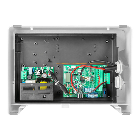
Beninca ZED24 User manual

CENTRALE DI COMANDO
CONTROL UNIT
STEUEREINHEIT
CENTRALE DE COMMANDE
CENTRAL DE MANDO
CENTRALKA STEROWANIA
L8542062
Rev. 12/05/03
ZED24
Libro istruzioni
Operating instructions
Betriebsanleitung
Livret d’instructions
Manual de instrucciones
Książeczka z instrukcjami
UNIONE NAZIONALE COSTRUTTORI
AUTOMATISMI PER CANCELLI, PORTE,
SERRANDE ED AFFINI

2
Dichiarazione CE di conformità Déclaration CE de conformité
EC declaration of conrmity Declaracion CE de conformidad
EG-Konformitatserklarung Deklaracja UE o zgodności
Con la presente dichiariamo che il nostro prodotto
We hereby declare that our product
Hiermit erklaren wir, dass unser Produkt
Nous déclarons par la présente que notre produit
Por la presente declaramos que nuestro producto
Niniejszym oświadczamy że nasz produkt
Cen ZED24
è conforme alle seguenti disposizioni pertinenti:
complies with the following relevant provisions:
folgenden einschlagigen Bestimmungen entspricht:
correspond aux dispositions pertinentes suivantes:
satisface las disposiciones pertinentes siguientes:
zgodny jest z poniżej wyszczególnionymi rozporządzeniami:
Direttiva sulla compatibilità elettromagnetica
(89/336/CCE, 93/68/CEE)
EMC guidelines (89/336/EEC, 93/68/EEC)
EMV-Richtlinie (89/336/EWG, 93/68/EWG)
Directive EMV (89/336/CCE, 93/68/CEE)
(Compatibilité électromagnétique)
Reglamento de compatibilidad electromagnética
(89/336/MCE, 93/68/MCE)
Wytyczna odnośnie zdolności współdziałania elektromagne-
tycznego (89/336/EWG, 93/68/EWG)
Benincà Luigi, Responsabile legale.
Sandrigo, 05/10/2005.
Direttiva sulla bassa tensione (73/23/CEE, 93/68/CEE)
Low voltage guidelines (73/23/EEC, 93/68/EEC)
Tiefe Spannung Richtlinie (73/23/EWG, 93/68/EWG)
Directive bas voltage (73/23/CEE, 93/68/CEE)
Reglamento de bajo Voltaje (73/23/MCE, 93/68/MCE)
Wytyczna odnośnie niskiego napięcia (73/23/EWG,
93/68/EWG)
Automatismi Benincà SpA
Via Capitello, 45
36066 Sandrigo (VI)
ITALIA

2

5

5
Centrale di comando ZED24
La centrale elettronica ZED24 può essere utilizzata per il controllo di 1/2 motori con potenza non superiore a 120W+120W.
Sono rappresentate le seguenti tipologie di installazione:
A) 1 Motore ZED24 con centrale incorporata: In fig.1, con riferimento allo schema generale “A”, collegare gli accessori come
indicato nello schema “C”.
B) 1 Motore ZED24 con centrale incorporata e un motore ZED24 senza centrale: In fig. 1 fare riferimento allo schema generale
“A e B” collegare gli accessori come nello schema “C” e collegare i due motori come indicato nello schema di Fig.2 “D”.
C) 1 Centrale ZED24 a parete e due motori ZED24 senza centrale: In fig. 1 fare riferimento allo schema generale “A e B”,
collegare gli accessori come nello schema “C” e collegare i due motori alla centrale come indicato nello schema di Fig.2 “E”.
IMPORTANTE: Nel caso di utilizzo di due motori, collegare alla centrale di comando i finecorsa di un solo motore.
AVVERTENZE GENERALI
a) L’installazione elettrica e la logica di funzionamento devono essere in accordo con le normative vigenti.
b) I conduttori alimentati con tensioni diverse, devono essere fisicamente separati, oppure devono essere adeguatamente isolati
con isolamento supplementare di almeno 1 mm.
c) I conduttori devono essere vincolati da un fissaggio supplementare in prossimità dei morsetti.
d) Ricontrollare tutti i collegamenti fatti prima di dare tensione.
e) Controllare che le impostazioni dei Dip-Switch siano quelle volute.
f) Gli ingressi N.C. non utilizzati devono essere ponticellati.
FUNZIONI INGRESSI/USCITE
Centrale ZED24
N° Morsetti Funzione Descrizione
1-2 Alimentazione Ingresso 230Vac 50Hz (1-Fase/2-Neutro)
3-4 Lampeggiante Collegamento lampeggiante 24Vac 40W max.
5-6 Luce Motore 2 Collegamento alla luce di cortesia del motore 2
(solo nel caso di utilizzo di 2 motori)
7 COM Comune per finecorsa e tutti gli ingressi di comando.
8 SWO Ingresso finecorsa APRE (contatto N.C.)
9 SWC Ingresso finecorsa CHIUDE (contatto N.C.)
10 STOP Ingresso pulsante STOP (contatto N.C.)
11 PHOT Ingresso collegamento dispositivi di sicurezza, contatto N.C.
(ad es. fotocellule)
12 OPEN Ingresso pulsante APRE (contatto N.O.)
13 CLOSE Ingresso pulsante CHIUDE (contatto N.O.)
14 Passo-Passo Ingresso pulsante passo-passo (contatto N.O.)
15-16 Motore1 Collegamento al motore 1 (15+/16-)
17-18 Motore 2 Collegamento al motore 2 (15+/16-)
da utilizzare solo nel caso di utilizzo di 2 motori
19-20 24 Vac Uscita alimentazione accessori 24Vac/1A max.
21-22 SCA Contatto pulito N.O. per spia cancello aperto.
23-24 COSTA Ingresso contatto costa sensibile
Costa resistiva: Jumper “DAS” chiuso
Costa meccanica: Jumper “DAS” aperto
L’intervento della costa durante la fase di apertura arresta il movimento dell’anta.
Durante la fase di chiusura arresta il movimento, inverte (apre) per 3s.
25-26 Antenna
Collegamento antenna scheda radioricevente ad innesto (25-schermo/26-segnale).
0-24-VMOT Secondario Collegamento avvolgimento secondario trasformatore
L1-N1 Primario Collegamento avvolgimento primario trasformatore
J3 Ricevitore Radio Connettore ad innesto per ricevente radio.

6
7
Scheda ZED24 SC
N° Morsetti Funzione Descrizione
1-2 + M2 Collegamento + del motore 2
3-4 - M2 Collegamento - del motore 2
7-8 Luce Motore 2 Collegamento alla luce di cortesia del Motore 2
9-10 COM Comune per finecorsa del Motore 2.
11-12 SWC Ingresso finecorsa CHIUDE
13-14 SWO Ingresso finecorsa APRE
Note:
a) Se presenti, i pulsanti a bordo del motore sono collegati ai comandi Passo/Passo e STOP.
Eventuali ulteriori sicurezze devono essere collegate in serie al comando STOP.
b) La luce di cortesia resta accesa per circa 90s ad ogni manovra.
c) La COSTA deve essere collegata esclusivamente agli appositi ingressi. Si possono utilizzare due tipi di COSTA:
Se si utilizza una costa con resistenza 8K2 chiudere il Jumper “DAS”.
Se si utilizza una costa meccanica con contatto N.C. aprire il Jumper “DAS”.
Se non si utilizza la costa ponticellare i morsetti 23-24.
Regolazione Finecorsa
1) Dare alimentazione alla centrale
2) Sbloccare manualmente e aprire completamente la porta.
3) Regolare la camma del finecorsa di apertura, il led SWO si spegne.
4) Chiudere completamente la porta.
5) Regolare la camma del finecorsa di chiusura, il led SWC si spegne.
6) Togliere alimentazione.
7) Portare la porta a circa metà della corsa e ribloccarla.
8) Ripristinare l’alimentazione. I led STOP, PHOT, SWO e SWC devono accendersi.
9) Dare un comando di passo-passo mediante pulsante o radiocomando.
10) La porta deve muoversi in apertura. Nel caso ciò non avvenisse, è sufficiente invertire tra loro i fili di marcia (15<>16) del motore
e gli ingressi finecorsa (SWO<>SWC).
11) Procedere con la regolazione dei Tempi e delle Logiche di funzionamento e della velocità motore.
Attivazione Rallentamento
Se si desidera il rallentamento in apertura e chiusura portare in ON il Dip-Switch 3.
Impostare il tempo di rallentamento con il Dip-Switch 8 e la velocità di rallentamento con il Dip-Switch 7.
La fase di rallentamento inizia in anticipo rispetto all’intervento dei finecorsa.
Per questo motivo, al primo avvio e dopo ogni interruzione di alimentazione di rete, la centrale deve eseguire una o più manovre
complete di apertura e chiusura, per apprendere il tempo di manovra totale e calcolare i relativi tempi di rallentamento.
Se si effettua una manovra completa di apertura/chiusura della porta PRIMA di attivare il Dip-Switch 3 (rallentamenti disabiltati), la
centrale memorizza la corsa completa e calcola i rallentamenti necessari evitando la fase di apprendimento.
Regolazione della velocità
ATTENZIONE! Questa regolazione influisce sul grado di sicurezza dell’automazione.
Verificare che la forza applicata sull’anta sia conforme con quanto previsto dalle normative vigenti.
Sul trasformatore di alimentazione è presente un connettore Faston (VMOT) che permette la regolazione della velocità dei motori su
3 diversi livelli. Posizionando il Faston (VMOT) su 15 si ha la velocità minore, spostandolo su 23 si ha la velocità maggiore.
Funzione dei Trimmer
AMP-O Permette di regolare la soglia di intervento del sensore di corrente durante al fase di apertura.
L’intervento del sensore durante la fase di apertura provoca l’arresto del motore.
AMP-C Permette di regolare la soglia di intervento del sensore di corrente durante al fase di chiusura.
L’intervento del sensore durante la fase di chiusura provoca:
- In fase rallentamento, l’arresto immediato del motore
- Durante la fase a velocità normale (non rallentata), inverte per 2 secondi e si arresta.
TCA Permette di regolare il tempo di chiusura automatica. Verificare il Dip-Switch N°1= On.
La regolazione varia da un minimo di 1s ad un massimo di 90s
Funzione Dip-Switch
DIP 1 “TCA” Abilita o disabilita la chiusura automatica.
Off: chiusura automatica disabilitata
On: chiusura automatica abilitata
6
7
DIP 2 “Prelam.” Abilita o disabilita il prelampeggio
Off: Prelampeggio disabilitato
On: Prelampeggio abilitato. Il lampeggiante si attiva 3s prima della partenza del motore.
DIP 3 “Rall.” Abilita o disabilita il rallentamento.
Off: rallentamento disabilitato.
Il finecorsa di apertura “SWO” arresta istantaneamente il motore.
Il finecorsa di chiusura “SWC” ritarda l’arresto del motore di 1,5s per consentire una migliore chiusura
On: Rallentamento attivo in apertura e chiusura.
DIP 4 “P.P. Mod” Seleziona la modalità di funzionamento del ”Pulsante P.P.” e del trasmettitore.
Off: Funzionamento: APRE > STOP > CHIUDE > STOP >
On: Funzionamento: APRE > CHIUDE > APRE >
DIP 5 “PHOT. AP.” Abilita o disabilita le fotocellule durante la fase di apertura.
Off: Fotocellule attivate durante la fase di apertura.
On: Fotocellule disattivate durante la fase di apertura. .
DIP 6 “Cond.” Abilita o disabilita la funzione condominiale.
Off: Funzione condominiale disabilitata.
On: Funzione condominiale abilitata. L’impulso P.P. o del trasmettitore non ha effetto durante la fase di
apertura.
DIP 7 “VRall” Selezione la velocità del motore durante la fase di rallentamento
Off: Velocità in rallentamento minima.
On: Velocità in rallentamento massima.
DIP 8 “TRall” Seleziona la durata in secondi della fase di rallentamento sia in chiusura sia in apertura.
Off: 3 secondi.
On: 7 secondi.
Diagnostica LED
La centrale dispone di una serie di LED di autodiagnosi che consentono il controllo di tutte le funzioni:
Led SW1 Si accende con l’attivazione del finecorsa di apertura SWO
Led SW2 Si accende con l’attivazione del finecorsa di chiusura SWC
Led STOP Si spegne con l’attivazione del pulsante STOP
Led PHOT Si spegne con fotocellule non allineate o in presenza di ostacoli
Led OPN Si accende con l’attivazione del pulsante OPEN
Led CLS Si accende con l’attivazione del pulsante CLOSE
Led PP Si accende con l’attivazione del pulsante PP
Led PGM Lampeggia ad indicare il regolare funzionamento della centrale.

8
9
ZED24 Control unit
The electronic control unit ZED24 can be used to control 1 or 2 motors with a power not exceeding 120W+120W.
The following types of installation are possible:
A) 1 Motor ZED24 with built-in control unit: In fig.1, with reference to the “A” general scheme, connect the accessories as
indicated in the “C” diagram.
B) 1 Motor ZED24 with built-in control unit and one motor ZED24 without control unit: In fig. 1, taking as a reference the “A”
and “B” general diagrams, connect the accessories as per “C” diagram and connect the two motors as indicated in the “D”
diagram shown in Fig. 2.
C) 1 Control unit ZED24 fitted to wall and two motors ZED24 without control unit: In fig. 1, taking as a reference the “A” and
“B” general diagrams, connect the accessories as per “C” diagram and connect the two motors as indicated in the “E” diagram
shown in Fig. 2.
IMPORTANT: Should two motors be used, connect the limit switches of one single motor to the control unit.
GENERAL WARNINGS
a) The wire connections and the operating logic should be in compliance with regulations in force.
b) The cables featuring different voltage should be detached, or adequately insulated by an additional insulation of at least 1 mm.
c) The cables should be further fastened in proximity to the terminals.
d) Check all connections before powering the unit.
e) Check that setting of the Dip-Switches are the required ones.
f) Normally Closed inputs which are not in use should be short-circuited 230VAC – keep to phase/neutral).
INPUT/OUTPUT FUNCTIONS
ZED24 Control Unit
Terminal No. Function Description
1-2 Power supply Input, 230VAC 50Hz (1-Phase/2-Neutral)
3-4 Flashing light Connection of flashing light, 24Vac 40W max.
5-6 Light, Motor 2 Connection to the courtesy light of motor 2
(only when 2 motors are in use)
7 COM Common for limit switch and all control inputs.
8 SWO Input, OPEN limit switch (N.C. contact)
9 SWC Input, CLOSE limit switch (N.C. contact)
10 STOP Input, STOP push button (N.C. contact)
11 PHOT Input, connection to safety devices, N.C. contact
(e.g. Photocells)
12 OPEN Input, OPEN push button (N.O. contact)
13 CLOSE Input, CLOSE push button (N.O. contact)
14 Step-by-Step Input, step-by-step push button (N.O. contact)
15-16 Motor 1 Connection to motor 1 (15+/16-)
17-18 Motor 2 Connection to motor 2 (15+/16-)
To be used only when 2 motors are in use
19-20 24 Vac Output, power supply of accessories, 24Vac/1A max.
21-22 SCA Free contact, N.O. for open door warning light.
23-24 COSTA Input, safety edge contact
Resistive edge: Closed “DAS” jumper
Mechanical edge: Open “DAS” jumper
If the safety edge is activated in the opening phase, the gate stops.
In the closing phase, the gate stops and the performs a movement reversion (opens) for
3s.
25-26 Aerial Connection to the radio receiver card of the aerial (25-screen/26-signal).
0-24-VMOT Secondary Connection, winding of secondary transformer
L1-N1 Primary Connection, winding of primary transformer
J3 Radio receiver Connector for radio receiver.

8
9
ZED24 SC Card
Terminal No. Function Description
1-2 + M2 + connection of motor 2
3-4 - M2 - connection of motor 2
7-8 Motor 2 light Connection to courtesy light of Motor 2
9-10 COM Common, limit switches of Motor 2.
11-12 SWC Input, CLOSE limit switch
13-14 SWO Input, OPEN limit switch
Remarks:
a) If present, the push buttons on the motor are connected to Step-by-Step and STOP controls.
Any further safety devices should be connected in series to the STOP control.
b) The courtesy light stays on for about 90s at each operation.
c) The safety EDGE should be connected only to the special inputs. Two types of EDGE can be used:
If a safety edge is used with 8K2 resistance, the “DAS” jumper should be closed.
If a mechanical safety edge with N.C. contact is used, the “DAS” Jumper should be opened.
If no edge is used, terminals 23-24 should be short-circuited.
To adjust the limit switches
1) Power the control unit
2) Manually release the system and completely open the door.
3) Adjust the opening limit switch cam, the SWO LED turns off.
4) Shut the door completely.
5) Adjust the closing limit switch cam, the SWC LED turns off.
6) Cut off power supply.
7) Move the door half-way and lock it again.
8) Reset power supply. The STOP, PHOT, SWO and SWC LED’s should light up.
9) Give a step-by-step control signal by pressing the appropriate button or using the remote control.
10) The door should move in the opening phase. In the negative, it is sufficient to invert the speed wires (15<>16) of the motor and
the limit switch inputs (SWO<>SWC).
11) Adjust Time, the Operating Logistics as well as the Motor speed.
Enabling Slowdown
To enable the slowdown option during opening and closing set Dip-Switch 3 to ON.
Set the slowdown time with Dip-Switch 8 and slowdown speed with Dip-Switch 7.
The slowdown cycle starts before the limit switches trip.
This is why, on the first start-up and every time the mains power is shutdown the control unit has to run one or more complete open
and close cycles to self-learn the total cycle time and calculate the relevant slowdown times.
If a complete open/close cycle is performed on the door BEFORE setting Dip-Switch 3 to ON (i.e. slowdowns left disabled), the
control unit can memorize the complete stroke and calculate the necessary slowdowns thereby avoiding the self-learn phase.
To adjust Speed
WARNING! This adjustment affects the safety level of the automatic system.
Make sure that the force applied onto the gate wing complies with regulations in force.
The supply transformer is provided with a Faston (VMOT) connector which permits to adjust the motor speed at three different levels.
When the Faston (VMOT) is on 15, the speed is at minimum. When the Faston is moved to 23, the maximum speed is obtained.
Function of Trimmers
AMP-O This trimmer allows to adjust the activation threshold of the current sensor in the opening phase.
When the sensor is triggered in the opening phase, the motor stops.
AMP-C This trimmer allows to adjust the activation threshold of the current sensor in the closing phase.
During closure, if the sensor is triggered :
The motor stops immediately in the braking phase
During the regular speed movement (not braked), the movement is reversed for 2 seconds and then stops.
TCA It allows to adjust the automatic closure time. Check Dip-Switch N°1= On.
The adjustment varies from 1s minimum to 90s maximum

10
11
Dip-Switch functions
DIP 1 “TCA” The automatic closure is enabled or disabled
Off: disabled automatic closure
On: enabled automatic closure
DIP 2 “Prelam.” Forewarning flashing light enabled or disabled
Off: disabled forewarning flashing light
On: enabled forewarning flashing light. The flashing light is activated 3 s before the starting of the motor.
DIP 3 “Rall.” Braking is enabled or disabled.
Off: disabled braking, the “SWO” opening limit switch stops the motor immediately. The “SWC” closure limit
switch delays the motor stop by 1.5s in order to allow a better closure of the door.
On: Braking in both opening and closing phases.
N.B.: the braking phase starts when the limit switches are triggered.
DIP 4 “P.P. Mod” The operating mode of “P.P. Push button” and of the transmitter are selected.
Off: Operation: OPEN > STOP > CLOSE > STOP >
On: Operation : OPEN > CLOSE > OPEN >
DIP 5 “PHOT. AP.” The photocells in the opening phase are enabled or disabled.
Off: enabled photocells in the opening phase.
On: disabled photocells in the opening phase.
DIP 6 “Cond.” The multi-flat function is enabled or disabled.
Off: disabled multi-flat function.
On: enabled multi-flat function. The P.P. (Step-by-step) impulse or the impulse of the transmitter have no
effect in the opening phase.
DIP 7 “VRall” Motor speed selection in the braking phase
Off: Minimum braking speed .
On: Maximum braking speed .
DIP 8 “TRall” This selects the braking phase time in seconds, in both opening and closing phases.
Off: 3 seconds.
On: 7 seconds.
LED Diagnostics
The control system has a series of self-diagnostics LED’s which allow to check all functions:
SW1 LED It switches on when the SWO opening limit switch is triggered
SW2 LED It switches on when the SWC closing limit switch is triggered
STOP LED It switches off when the STOP push button is pressed
PHOT LED It switches off when the photocells are not aligned or if obstacles are present
OPN LED It switches on when the OPEN push button is pressed
CLS LED It switches on when the CLOSE push button is pressed
PP LED It switches on when the PP push button is pressed
PGM LED It flashes to show the correct operation of the control unit.

10
11
Steuereinheit ZED24
Die elektronische Zentrale ZED24 kann zur Steuerung von 1 bzw. 2 Motoren mit einer Leistung von maximal 120W+120W verwendet
werden.
Hierfür gibt es drei Installationsmöglichkeiten:
A) 1 Motor ZED24 mit eingebauter Zentrale: In Abb. 1, mit Bezug auf den allgemeinen Plan „A“, das Zubehör laut Angaben des
Plans „C“ anschließen.
B) 1 Motor ZED24 mit eingebauter Zentrale und einem Motor ZED24 ohne Zentrale: In Abb. 1 mit Bezug auf den allgemeinen
Plan „A und B“, das Zubehör laut Plan „C“ und die beiden Motoren laut Anweisungen des Plans „D“, Abb. 2, anschließen.
C) 1 Zentrale ZED24 für die Wandmontage und zwei Motoren ZED24 ohne Zentrale: In Abb. 1 mit Bezug auf den allgemeinen
Plan „A und B“, das Zubehör laut Plan „C“ und die beiden Motoren laut Anweisungen des Plans „E“, Abb. 2, anschließen.
WICHTIG: Wenn zwei Motoren installiert werden, nur die Endschalter eines einzigen Motors an die Steuereinheit
schließen.
ALLGEMEINE HINWEISE
a) Die elektrische Installation und die Betriebslogik müssen den geltenden Vorschriften entsprechen.
b) Die Leiter die mit unterschiedlichen Spannungen gespeist werden, müssen physisch getrennt oder sachgerecht mit einer
zusätzlichen Isolierung von mindestens 1 mm isoliert werden.
c) Die Leiter müssen in der Nähe der Klemmen zusätzlich befestigt werden.
d) Alle Anschlüsse nochmals prüfen, bevor die Zentrale mit Strom versorgt wird.
e) Kontrollieren, ob die Dip-Schalter richtig positioniert sind.
f) Die nicht verwendeten N.C. Eingänge müssen überbrückt werden.
FUNKTIONEN EINGÄNGE/AUSGÄNGE
Zentrale ZED24
Klemme Funktion Beschreibung
1-2 Speisung Eingang 230Vac 50Hz (1-Phase/2-Nulleiter)
3-4 Blinkleuchte Ausgang Anschluss Blinkleuchte 24Vac 40W max.
5-6 Leuchte Motor 2 Anschluss an die Höflichkeitsleuchte des Motors 2
(nur wenn 2 Motoren installiert werden)
7 COM Gemein für alle Steuerungseingänge.
8 SWO Eingang Endschalter ÖFFNEN (Kontakt N.C.)
9 SWC Eingang Endschalter SCHLIESSEN (Kontakt N.C.)
10 STOPP Eingang STOPP-Taste (Kontakt N.C.)
11 PHOT Eingang zum Anschluss von Sicherheitsvorrichtungen, Kontakt N.C. (z.B. Photozellen)
12 OPEN Eingang Taste ÖFFNEN (Kontakt N.O.)
13 CLOSE Eingang Taste SCHLIESSEN (Kontakt N.O.)
14 Schritt-Schritt Eingang Taste Schritt-Schritt (Kontakt N.O.)
15-16 Motor 1 Anschluss an den Motor 1 (15+/16-)
17-18 Motor 2 Anschluss an den Motor 2 (15+/16-)
Nur im Falle der Verwendung von 2 Motoren
19-20 24 Vac Ausgang Zubehörspeisung 24Vac/1A max.
21-22 SCA Reiner Kontakt N.O. Für Meldeleuchte Tor offen
23-24 FLANKE Eingang Kontakt Näherungsflanke
Widerstandsfähige Flanke: Jumper “DAS” geschlossen
Mechanische Flanke: Jumper “DAS” geöffnet
Wenn die Flanke beim Öffnen eingeschaltet wird, hält die Flügelbewegung an.
Beim Schließen wird die Bewegung angehalten und 3 sec. lang umgeschaltet (öffnen).
25-26 Antenne Anschluss Antenne der Karte des steckbaren Funkempfängers und des eingebauten
Funkmoduls (25-Schirm/26-Signal).
0-24-VMOT Sekundär Anschluss Sekundärwicklung Trafo
L1-N1 Primär Anschluss Primärwicklung Trafo
J3 Funkempfänger Steckverbinder für Funkempfänger.

12
13
Karte ZED24 SC
Klemme Funktion Beschreibung
1-2 + M2 Anschluss + des Motors 2
3-4 - M2 Anschluss - des Motors 2
7-8 Licht Motor 2 Anschluss an das Höflichkeitslicht des Motors 2
9-10 COM Gemein für Endschalter des Motors 2
11-12 SWC Eingang Endschalter SCHLIESSEN
13-14 SWO Eingang Endschalter ÖFFNEN
Bemerkungen:
a) Wenn vorhanden, sind die Tasten an Bord des Motors mit den Steuerungen Schritt-Schritt und STOPP verbunden.
Andere Sicherheitsvorrichtungen müssen ggf. an die STOPP Steuerung in Reihe geschaltet werden.
b) Das Höflichkeitslicht bleibt bei jeder Bewegung circa 90 sec. lang eingeschaltet.
c) Die FLANKE darf nur an die entsprechenden Eingänge geschlossen werden. Es können zwei unterschiedliche FLANKENtypen
verwendet werden:
Wenn eine Flanke mit einem Widerstand von 8K2 verwendet wird, den Jumper “DAS” schließen.
Wenn eine mechanische Flanke mit Kontakt N.C. verwendet wird, den Jumper “DAS” öffnen.
Wird keine Flanke verwendet, die Klemmen 23-24 überbrücken.
Einstellung der Endschalter
1) Die Zentrale mit Strom versorgen.
2) Von Hand entsichern und die Tür vollständig öffnen.
3) Den Nocken des Endschalters für das Öffnen einstellen; die Leuchte SWO erlischt.
4) Türe schließen.
5) Den Nocken des Endschalters für das Schließen einstellen, die Leuchte SWC erlischt.
6) Strom abtrennen.
7) Tür bis auf den halben Hub öffnen und wieder blockieren.
8) Wieder Strom geben. Die Leuchten STOPP, PHOT, SWO und SWC müssen aufleuchten.
9) Über die Taste oder die Fernbedienung einen Schritt-Schritt Befehl geben.
10) Die Tür muss sich öffnen. Sollte dies nicht der Fall sein, genügt es die Leiter (15<>16) für den Motorenbetrieb und die Eingänge
der Endschalter (SWO<>SWC) vertauschen.
11) Zeiten, Betriebslogik sowie Motorenleistung einstellen
Aktivierung der Verlangsamung
Ist eine Verlangsamung bei Öffnen und Schließen erwünscht, den Dip-Switch 3 auf ON stellen.
Die Verlangsamungszeit mit dem Dip-Switch 8 und die Verlangsamungsgeschwindigkeit mit dem Dip-Switch 7 einstellen.
Die Verlangsamungsphase beginnt vor Auslösen der Endschalter.
Aus diesem Grund muss die Steuerzentrale beim erstmaligen Start und nach jeder Unterbrechung der Stromversorgung ein
oder mehrere komplette Öffnungs- und Schließmanöver durchführen, um die Gesamtzeit des Vorgangs zu erlernen und die
entsprechenden Verlangsamungszeiten zu berechnen.
Wird VOR Aktivieren des Dip-Switch 3 (Verlangsamungen deaktiviert) ein komplettes Öffnungs- und Schließmanöver des Tors
durchgeführt, speichert die Zentrale den kompletten Weg und berechnet die erforderlichen Verlangsamungen unter Auslassung der
Lernphase.
Geschwindigkeit einstellen
ACHTUNG! Diese Einstellung hat Einfluss auf die Sicherheit der Automatik.
Die für das Tor angewendete Kraft muss den geltenden Vorschriften entsprechen.
Der Speisetrafo ist mit einem Faston Verbinder (VMOT) versehen, durch den die Motorengeschwindigkeit auf 3 verschiedene Stufen
eingestellt werden kann. Wird der Faston Verbinder (VMOT) auf 15 eingestellt, wird die Motorengeschwindigkeit auf das Minimum
geregelt; wird er auf 23 eingestellt, wird die maximale Motorengeschwindigkeit erreicht.
Trimmer-Funktionen
AMP-O Ermöglicht es das Einschalten des Stromsensors während des Öffnens einzustellen.
Schaltet der Sensor beim Öffnen ein, so wird der Motor angehalten.
AMP-C Ermöglicht es das Einschalten des Stromsensors während des Schließens einzustellen.
Das Einschalten des Sensors beim Schließen bewirkt:
Während der Geschwindigkeitsabnahme, das sofortige Anhalten des Motors
Bei normaler Geschwindigkeit (ohne Geschwindigkeitsabnahme), erfolgt ein 2 Sekunden langes Umschalten und dann das
Anhalten.
TCA Ermöglicht es die Zeit des automatischen Schließvorgangs einzustellen. Kontrollieren ob Dip-Schalter Nr. 1= On.
Die Zeit kann zwischen 1 sec. und maximal 90 sec. eingestellt werden.

12
13
Dip-Schalter-Funktionen
DIP 1 “TCA” Aktiviert oder deaktiviert den automatischen Schließvorgang.
Off: automatischer Schließvorgang deaktiviert
On: automatischer Schließvorgang aktiviert
DIP 2 “Prelam.” Aktiviert oder deaktiviert das Vorblinken.
Off: Vorblinken deaktiviert
On: Vorblinken aktiviert. Das Vorblinken beginnt 3 sec. vor dem Einschalten des Motors.
DIP 3 “Rall.” Aktiviert oder deaktiviert die Geschwindigkeitsabnahme.
Off: Geschwindigkeitsabnahme deaktiviert: der Endschalter für das Öffnen “SWO” hält den Motor unverzüglich
an. Der Endschalter für das Schließen “SWC” verzögert das Anhalten des Motors um 1,5 sec. damit sich das
Tor richtig schließen kann.
On: Aktive Geschwindigkeitsabnahme beim Öffnen und Schließen.
Bemerkung: die Geschwindigkeitsabnahme beginnt, wenn die Endschalter erreicht werden.
DIP 4 “P.P. Mod” Wählt die Betriebsweise der Taste P.P.“ und des Sendegeräts.
Off: Betrieb: ÖFFNEN > STOPP > SCHLIESSEN > STOPP >
On: Betrieb: ÖFFNEN > SCHLIESSEN > ÖFFNEN >
DIP 5 “PHOT. AP.” Aktiviert oder deaktiviert die Fotozellen wenn das Tor geöffnet wird.
Off: Fotozellen beim Öffnen aktiviert.
On: Fotozellen beim Öffnen deaktiviert.
DIP 6 “Cond.” Aktiviert oder deaktiviert die Funktion Wohngemeinschaft.
Off: Funktion Wohngemeinschaft deaktiviert.
On: Funktion Wohngemeinschaft aktiviert. Auf den Öffnungsvorgang haben weder der Schritt-Schritt-Impuls
noch der Impuls des Sendegeräts Einfluss.
DIP 7 “VRall” Wahl der Motorengeschwindigkeit während der Geschwindigkeitsabnahme
Off: Mindeste Geschwindigkeitsabnahme.
On: Maximale Geschwindigkeitsabnahme.
DIP 8 “TRall” Wählt die Dauer in Sekunden der Geschwindigkeitsabnahme sowohl beim Schließen als auch beim Öffnen
Off: 3 Sekunden.
On: 7 Sekunden.
Diagnostik der Leuchten
Die Zentrale verfügt über eine Reihe von Leuchten zur Selbstdiagnostik über welche alle Funktionen kontrolliert werden können:
Led SW1 Schaltet ein, wenn der Endschalter SWO für das Öffnen aktiviert wird.
Led SW2 Schaltet ein, wenn der Endschalter SWC für das Schließen aktiviert wird.
Led STOP Schaltet aus, wenn die STOPP Taste aktiviert wird
Led PHOT Schaltet aus, wenn Fotozellen nicht gefluchtet sind oder Hindernisse vorhanden sind.
Led OPN Schaltet ein, wenn die Taste OPEN aktiviert wird
Led CLS Schaltet ein, wenn die Taste CLOSE aktiviert wird.
Led PP Schaltet ein, wenn die Taste PP aktiviert wird.
Led PGM Blinkt, was bedeutet dass die Zentrale ordentlich funktioniert.

14
15
Centrale de commande ZED24
La centrale électronique ZED24 peut être utilisée pour le contrôle de 1 ou 2 moteurs ayant une puissance ne dépassant pas les
120W+120W.
Les typologies d’installation suivantes sont représentées:
A) 1 Moteur ZED24 avec centrale incorporée: fig.1, en se référant au schéma général “A”, connecter les accessoires de la
manière indiquée au schéma “C”.
B) 1 Moteur ZED24 avec centrale incorporée et un moteur ZED24 sans centrale: fig. 1 en se référant aux schémas généraux
“A et B”, connecter les accessoires de la manière indiquée au schéma “C” et connecter les deux moteurs de la manière
indiquée au schéma Fig.2 “D”.
C) 1 Centrale ZED24 murale et deux moteurs ZED24 sans centrale: fig. 1 faire référence aux schémas généraux “A et B”,
connecter les accessoires de la manière indiquée au schéma “C” et connecter les deux moteurs à la centrale de la manière
indiquée au schéma Fig.2 “E”.
IMPORTANT: En cas d’utilisation de deux moteurs, connecter à la centrale de commande les fins de course d’un seul
moteur
AVERTISSEMENTS GENERAUX
a) L’installation électrique et la logique de fonctionnement doivent être conformes aux normes en vigueur.
b) Les conducteurs alimentés avec des tensions différentes doivent être séparés physiquement, ou adéquatement isolés avec une
isolation supplémentaire d’au moins 1 mm.
c) Les conducteurs doivent être contraints par une fixation supplémentaire à proximité des bornes.
d) Avant de mettre sous tension, contrôler à nouveau toutes les connexions réalisées.
e) Contrôler que les réglages des dip-switches sont ceux désirés.
f) Réaliser un pontet sur les entrées N.F. non utilisées.
FONCTIONS ENTREES/SORTIES
Centrale ZED24
N. Bornes Fonction Description
1-2 Alimentation Entrée 230Vac 50Hz (1-Phase/2-Neutre)
3-4 Clignotant Connexion clignotant 24Vac 40W max.
5-6 Lumière Moteur 2 Connexion à la lumière de courtoisie du moteur 2
(seulement en cas d’utilisation de 2 moteurs)
7 COM Commun pour fins de course et toutes les entrées de commande.
8 SWO Entrée fin de course OUVRIR (contact N.F.)
9 SWC Entrée fin de course FERMER (contact N.F.)
10 STOP Entrée bouton STOP (contact N.F.)
11 PHOT Entrée connexion dispositifs de sécurité, contact N.F.
(par ex. photocellules)
12 OPEN Entrée bouton OUVRIR (contact N.O.)
13 CLOSE Entrée bouton FERMER (contact N.O.)
14 Pas à pas Entrée bouton pas à pas (contact N.O.)
15-16 Moteur 1 Connexion au moteur 1 (15+/16-)
17-18 Moteur 2 Connexion au moteur 2 (15+/16-)
S’emploie seulement en cas d’utilisation de 2 moteurs
19-20 24 Vac Sortie alimentation accessoires 24Vac/1A max.
21-22 SCA Contact libre N.O. pour voyant portail ouvert.
23-24 Bourrelet Entrée contact bourrelet sensible
Bourrelet résistif: Jumper “DAS” fermé
Bourrelet mécanique: Jumper “DAS” ouvert
L’intervention du bourrelet durant l’ouverture arrête le mouvement de la porte.
Durant la fermeture il arrête le mouvement et l’inverse (ouvre) pendant 3s.
25-26 Antenne Connexion antenne carte récepteur radio à enclenchement (25- écran/26-signal).
0-24-VMOT Secondaire Connexion enroulement secondaire transformateur
L1-N1 Primaire Connexion enroulement primaire transformateur
J3 Récepteur radio Connecteur à enclenchement pour récepteur radio.

14
15
Carte ZED24 SC
N° Bornes Fonction Description
1-2 + M2 Connexion + du moteur 2
3-4 - M2 Connexion - du moteur 2
7-8 Lumière Moteur 2 Connexion à la lumière de courtoisie du moteur 2
9-10 COM Commun pour fin de course du moteur 2.
11-12 SWC Entrée fin de course FERMER
13-14 SWO Entrée fin de course OUVRIR
Note:
a) Si présents, les boutons embarqués sur le moteur sont branchés aux commandes pas à pas et STOP.
Toutes les sécurités ultérieures doivent être branchées en série à la commande de STOP.
b) A chaque manœuvre, la lumière de courtoisie demeure allumée pendant environ 90s.
c) Le BOURRELET doit être exclusivement connecté aux entrées prévues. Deux types de bourrelets peuvent être utilisés:
Si on utilise un bourrelet avec une résistance 8K2, fermer le Jumper “DAS”.
Si on utilise un bourrelet mécanique avec un contact N.F. ouvrir le Jumper “DAS”.
Si on n’utilise pas de bourrelet, réaliser un pontet aux bornes 23-24.
Réglage des fins de course
1) Alimenter la centrale
2) Déverrouiller manuellement et ouvrir complètement la porte.
3) Régler la came du fin de course d’ouverture, la led SWO s’éteint.
4) Fermer complètement la porte.
5) Régler la came du fin de course de fermeture, la led SWC s’éteint.
6) Couper l’alimentation.
7) Amener la porte à environ la moitié de sa course et la rebloquer.
8) Restaurer l’alimentation. Les leds STOP, PHOT, SWO et SWC doivent s’éclairer.
9) Donner une commande pas à pas en intervenant sur le bouton ou sur la radiocommande.
10) La porte doit se déplacer en ouverture. Si cela n’a pas lieu, il suffira d’inverser entre eux les fils de marche (15<>16) du moteur
et les entrées des fins de course (SWO<>SWC).
11) Régler les temps et les logiques de fonctionnement, ainsi que la vitesse du moteur.
Activation Ralentissement
Si l’on souhaite le ralentissement en ouverture et en fermeture, mettre le Dip-Switch 3 sur ON.
Régler le temps de ralentissement avec le Dip-Switch 8 et la vitesse de ralentissement avec le Dip-Switch 7.
La phase de ralentissement commence avant que les fins de course interviennent.
Pour cette raison, à la première mise en service et après chaque coupure de courant, la logique de commande doit effectuer une
ou plusieurs manœuvres complètes d’ouverture et de fermeture pour apprendre le temps de manœuvre total et calculer les temps
de ralentissement correspondants.
Si l’on effectue une manœuvre complète d’ouverture/fermeture de la porte AVANT d’activer le Dip-Switch 3 (ralentissements
désactivés), la logique de commande mémorise la course complète et calcule les ralentissements nécessaires en évitant la phase
d’apprentissage.
Réglage de la vitesse
ATTENTION! Ce réglage influe sur le degré de sécurité de l’automation.
Vérifier que la force appliquée sur la porte est conforme aux préconisations des normes en vigueur.
Le transformateur d’alimentation monte un connecteur Faston (VMOT) permettant de régler la vitesse des moteurs sur 3 niveaux
différents. Placer le Faston (VMOT) sur 15 pour obtenir la plus petite vitesse, et sur 23 pour obtenir la vitesse maximum.
Fonction des Trimmers
AMP-O Permet de régler le seuil d’intervention du capteur de courant durant l’ouverture.
L’intervention du capteur durant l’ouverture provoque l’arrêt du moteur.
AMP-C Permet de régler le seuil d’intervention du capteur de courant durant la fermeture.
L’intervention du capteur durant la fermeture provoque:
En ralentissement, l’arrêt immédiat du moteur
Durant la phase à vitesse normale (non ralentie), inverse pendant 2 secondes et s’arrête.
TCA Permet de régler le temps de fermeture automatique. Vérifier le Dip-Switch N°1= On.
Le réglage varie d’un minimum de 1 s à un maximum de 90s

16
17
Fonction Dip-Switch
DIP 1 “TCA” Valide ou invalide la fermeture automatique.
Off: fermeture automatique invalidée
On: fermeture automatique validée
DIP 2 “Pré-clign.” Valide ou invalide le clignotement
Off: Clignotement invalidé
On: Clignotement validé. Le clignotement s’active 3s avant le démarrage du moteur.
DIP 3 “Ral.” Valide ou invalide le ralentissement.
Off: ralentissement invalidé. Le fin de course d’ouverture “SWO” arrête instantanément le moteur. Le fin de
course de fermeture “SWC” retarde l’arrêt du moteur di 1,5s pour consentir une meilleure fermeture de la porte
On: Ralentissement actif en ouverture et en fermeture.
Note: La phase de ralentissement commence par l’interception du fin de course.
DIP 4 “P.P. Mod” Sélectionne le mode de fonctionnement du ”Bouton P.P.” et de l’émetteur.
Off: Fonctionnement: OUVRIR > STOP > FERMER > STOP >
On: Fonctionnement: OUVRIR > FERMER > OUVRIR >
DIP 5 “PHOT. AP.” Valide ou invalide les photocellules durant l’ouverture.
Off: Photocellules activées durant l’ouverture.
On: Photocellules désactivées durant l’ouverture. .
DIP 6 “Cond.” Valide ou invalide la fonction copropriété.
Off: Fonction copropriété invalidée.
On: Fonction copropriété validée. L’impulsion P.P. ou de l’émetteur n’a aucun effet durant l’ouverture.
DIP 7 “VRall” Sélection de la vitesse du moteur durant le ralentissement
Off: Vitesse en ralentissement minimum.
On: Vitesse en ralentissement maximum.
DIP 8 “TRall” Sélection de la durée en secondes du ralentissement aussi bien en fermeture qu’en ouverture.
Off: 3 secondes.
On: 7 secondes.
Diagnostic leds
La centrale dispose d’une série de leds d’autodiagnostic qui permettent le contrôle de toutes les fonctions.
Led SW1 Elle s’éclaire lorsque le fin de course d’ouverture SWO s’active.
Led SW2 Elle s’éclaire lorsque le fin de course de fermeture SWC s’active.
Led STOP Elle s’éteint lorsqu’on intervient sur le bouton STOP
Led PHOT Elle s’éteint lorsque les photocellules ne sont pas alignées ou en présence d’obstacles
Led OPN Elle s’éclaire lorsqu’on intervient sur le bouton OPEN
Led CLS Elle s’éclaire lorsqu’on intervient sur le bouton CLOSE
Led PP Elle s’éclaire lorsqu’on intervient sur le bouton PP
Led PGM Elle clignote pour indiquer que la centrale fonctionne régulièrement.

16
17
Central de control ZED24
La central electrónica ZED24 se puede utilizar para controlar 1/2 motores con potencia no mayor que 120W+120W.
Se muestran los siguientes tipos de instalación:
A) 1 Motor ZED24 con central incorporada: En la fig.1, con referencia al esquema general “A”, conectar los accesorios como
indicado en el esquema “C”.
B) 1 Motor ZED24 con central incorporada y un motor ZED24 sin central: En la fig. 1 hacer referencia al esquema general “A
y B” conectar los accesorios como en el esquema “C” y conectar los dos motores como indicado en el esquema de la Fig.2
“D”.
C) 1 central ZED24 de pared y dos motores ZED24 sin central: En la fig. 1 hacer referencia al esquema general “A y B” conectar
los accesorios como en el esquema “C” y conectar los dos motores como indicado en el esquema de la Fig.2 “E”.
IMPORTANTE: Si se utilizan dos motores, conectar con la central de control los final de carrera de un solo motor.
ADVERTENCIAS GENERALES
a) La instalación eléctrica y la lógica de funcionamiento deben cumplir las normas vigentes.
b) Los conductores alimentados con tensiones distintas deben estar físicamente separados, o bien deben estar adecuadamente
aislados con aislamiento suplementario de por lo menos 1 mm.
c) Los conductores deben estar vinculados por una fijación suplementaria cerca de los bornes.
d) Comprobar todas las conexiones efectuadas antes de dar la tensión.
e) Comprobar que las configuraciones de los Dip-Switch sean las deseadas.
f) Las entradas N.C. no utilizadas deben estar puenteadas.
FUNCIONES ENTRADAS/SALIDAS
Central ZED24
N° Bornes Función Descripción
1-2 Alimentación Entrada 230Vac 50Hz (1-Fase/2-Neutro)
3-4 Intermitente Conexión intermitente 24VCA 40W máx.
5-6 Luz Motor 2 Conexión con la luz de cortesía del motor 2
(sólo si se usan 2 motores)
7 COM Común para final de carrera y todas las entradas de control.
8 SWO Entrada final de carrera ABRE (contacto N.C.)
9 SWC Entrada final de carrera CIERRA (contacto N.C.)
10 STOP Entrada botón STOP (contacto N.C.)
11 PHOT Entrada conexión dispositivos de seguridad, contacto N.C.
(por ej. fotocélulas)
12 OPEN Entrada botón ABRE (contacto N.A.)
13 CLOSE Entrada botón CIERRA (contacto N.A.)
14 Paso-Paso Entrada botón paso-paso (contacto N.A.)
15-16 Motor 1 Conexión con el motor 1 (15+/16-)
17-18 Motor 2 Conexión con el motor 2 (15+/16-)
a utilizar sólo si se utilizan 2 motores
19-20 24 Vac Salida alimentación accesorios 24Vac/1A máx.
21-22 SCA Contacto limpio N.A. para chivato cancela abierta.
23-24 BORDE Entrada contacto borde sensible
Borde resistivo: Puente “DAS” cerrado
Borde mecánico: Puente “DAS” abierto
La actuación del borde durante la fase de apertura detiene el movimiento de la puerta.
Durante la fase de cierre detiene el movimiento, invierte (abre) por 3s.
25-26 Antena Conexión antena tarjeta radioreceptora de enchufe (23-pantalla/24-señal).
0-24-VMOT Secundario Conexión bobinado secundario transformador
L1-N1 Primario Conexión bobinado primario transformador
J3 Receptor Radio Conector enchufable para receptora radio.

18
19
Tarjeta ZED24 SC
N° Bornes Función Descripción
1-2 + M2 Conexión + del motor 2
3-4 - M2 Conexión - del motor 2
7-8 Luz Motor 2 Conexión con la luz de cortesía del Motor 2
9-10 COM Común para nal de carrera del Motor 2.
11-12 SWC Entrada nal de carrera CIERRA
13-14 SWO Entrada nal de carrera ABRE
Notas:
a) Si presentes, los pulsadores a bordo del motor están conectados con los comandos Paso/Paso y STOP.
Eventuales ulteriores seguridades se deben conectar en serie con el comando STOP.
b) La luz de cortesía queda encendida durante aproximadamente 90s a cada maniobra.
c) El BORDE debe estar conectado exclusivamente con sus correspondientes entradas. Se pueden utilizar dos tipos de BORDE
(Costa):
Si se utiliza un borde con resistencia 8K2 cerrar el Puente “DAS”.
Si se utiliza un borde mecánico con contacto N.C. abrir el Puente “DAS”.
Si no se utiliza el borde puentear los bornes 23-24.
Regulación Final de carrera
1) Dar alimentación a la central
2) Desbloquear manualmente y abrir completamente la puerta.
3) Ajustar la excéntrica del final de carrera de apertura, el LED SWO se apaga.
4) Cerrar completamente la puerta.
5) Ajustar la excéntrica del final de carrera de cierre, el LED SWC se apaga.
6) Cortar la alimentación.
7) Llevar la puerta a aproximadamente mitad de la carrera y boquearla de nuevo.
8) Restablecer la alimentación. Los LEDs STOP, PHOT, SWO y SWC deben encenderse.
9) Dar un comando de paso-paso con botón o mando a distancia.
10) La puerta debe moverse en apertura. En caso contrario basta invertir entre ellos los hilos de marcha (15<>16) del motor y las
entradas final de carrera (SWO<>SWC).
11) Proceder con la regulación de los Tiempos y de las Lógicas de funcionamiento y de la velocidad motor.
Activación de la deceleración
Si se desea decelerar en apertura y cierre, poner el Dip-Switch 3 en ON.
Configurar el tiempo de deceleración con el Dip-Switch 8 y la velocidad de deceleración con el Dip-Switch 7.
La fase de deceleración comienza antes de la intervención del fin de carrera.
Por esta razón, la centralita deberá efectuar una o varias maniobras completas de apertura y cierre en la primera puesta en marcha
y después de cada interrupción de alimentación de red, para aprender el tiempo de maniobra total y calcular los relativos tiempos
de deceleración.
De efectuarse una maniobra completa de apertura/cierre de la puerta ANTES de activar el Dip-Switch 3 (deceleraciones
deshabilitadas), la centralita memoriza la carrera completa y calcula las deceleraciones necesarias, evitando la fase de
aprendizaje.
Regulación de la velocidad
¡ATENCIÓN! Esta regulación repercute en el grado de seguridad de la automatización.
Comprobar que la fuerza aplicada sobre la hoja sea conforme con cuanto previsto por las normas vigentes.
En el transformador de alimentación hay presente un conector Faston (VMOT) que permite la regulación de la velocidad de los
motores en 3 niveles distintos. Poniendo el Faston (VMOT) en 15 se tiene la velocidad más lenta, desplazándolo en 23 se tiene la
mayor velocidad.
Función de los Trimmer
AMP-O Permite ajustar el umbral de actuación del sensor de corriente durante al fase de apertura.
La actuación del sensor durante la fase de apertura provoca la parada del motor.
AMP-C Permite ajustar el umbral de actuación del sensor de corriente durante al fase de cierre.
La actuación del sensor durante la fase de cierre provoca:
En la fase de ralentización, la parada inmediata del motor
Durante la fase con velocidad normal (no ralentizada), invierte por 2 segundos y se para.
TCA Permite ajustar el tiempo de cierre automático. Comprobar el Dip-Switch N°1= On.
La regulación varía entre un mínimo de 1s y un máximo de 90s

18
19
Función Dip-Switch
DIP 1 “TCA” Habilita o inhabilita el cierre automático.
Off: cierre automático inhabilitado
On: cierre automático habilitado
DIP 2 “Prelam.” Habilita o inhabilita la pre-intermitencia.
Off: Intermitencia previa inhabilitada
On: Intermitencia previa habilitada. El intermitente se activa 3s antes del arranque del motor.
DIP 3 “Ralent.” Habilita o inhabilita la ralentización.
Off: ralentización inhabilitada. El final de carrera de apertura “SWO” detiene instantáneamente el motor. El
final de carrera de cierre “SWC” retrasa la parada del motor en 1,5s para consentir un mejor cierre de la
puerta
On: Ralentización activa en apertura y cierre.
Nota: la fase de ralentización comienza con la interceptación de los final de carrera.
Programar con el condensador de ajuste “TSLOW” un tiempo de ralentización ligeramente mayor que el
tiempo necesario para terminar la maniobra.
DIP 4 “P.P. Mod” Selecciona la modalidad de funcionamiento del ”Botón P.P.” y del transmisor.
Off: Funcionamiento: ABRE > STOP > CIERRA > STOP >
On: Funcionamiento: ABRE > CIERRA > ABRE >
DIP 5 “PHOT. AP.” Habilita o inhabilita las fotocélulas durante la fase de apertura.
Off: Fotocélulas activadas durante la fase de apertura.
On: Fotocélulas desactivadas durante la fase de apertura. .
DIP 6 “Com.” Habilita o inhabilita la función comunidad.
Off: Función comunidad inhabilitada.
On: Función comunidad habilitada. El impulso P.P. o del transmisor no tiene efecto durante la fase de
apertura.
DIP 7 “VRall” Selección de la velocidad del motor durante la fase de ralentización
Off: Velocidad en ralentización mínima.
On: Velocidad en ralentización máxima.
DIP 8 “TRall” Selecciona la duración, en segundos, de la fase de ralentización tanto en cierre como en apertura.
Off: 3 segundos.
On: 7 segundos.
Diagnóstico LED
La central tiene una serie de LEDs de autodiagnosis que permiten controlar todas las funciones:
LED SW1 Se enciende con la activación del final de carrera de apertura SWO
LED SW2 Se enciende con la activación del final de carrera de cierre SWC
LED STOP Se apagar con la activación del botón STOP
LED PHOT Se apaga con fotocélulas no alineadas o ante obstáculos
LED OPN Se enciende con la activación del botón OPEN
LED CLS Se enciende con la activación del botón CLOSE
LED PP Se enciende con la activación del botón PP
LED PGM Parpadea para indicar el funcionamiento correcto de la central.

20
21
Centralka sterowania ZED24
Elektroniczna centralka ZED24 może być stosowana do sterowania 1-2 silnikami o mocy nie większej jak 120W+120W.
Poniżej przedstawiona jest konguracja typu instalacji:
A) 1 silnik ZED24 z centralką wbudowaną – zobacz schemat generalny “A” na rysunku 1; należy podłączyć akcesoria tak, jak wskazano
na schemacie “C”.
B) 1 silnik ZED24 z centralką wbudowaną oraz jeden silnik ZED24 bez centralki – na rysunku 1 zobacz schematy generalne “A” i „B”;
należy podłączyć akcesoria tak, jak wskazane na schemacie “C” oraz podłączyć oba silniki tak, jak wskazano na schemacie „D”, rysunek
2.
C) 1 Centralka ZED24 do zamontowania na murze i dwa silniki ZED24 bez centralki - na rysunku 1 zobacz schematy generalne
“A” i „B”; należy podłączyć akcesoria tak jak wskazane na schemacie “C” oraz podłączyć oba silniki do centralki tak jak wskazano na
schemacie „E”, rysunek 2.
UWAGA: W przypadku zainstalowania dwu silników należy podłączyć do centralki sterowania wyłącznik krańcowy tylko
jednego silnika.
OSTRZEŻENIA OGÓLNE
a) Instalacja elektryczna oraz system działania urządzenia muszą być zgodne z obowiązującymi normami.
b) Przewody zasilane różnego rodzaju napięciem muszą być oddzielone od siebie lub odpowiednio izolowane z zastosowaniem dodatkowej
izolacji o grubości co najmniej 1 mm.
c) W pobliżu zacisków przewody muszą być przymocowane dodatkowym umocowaniem.
d) Przed włączeniem zasilania należy ponownie sprawdzić wszystkie podłączenia.
e) Sprawdzić czy wszystkie ustawienia Dip-Switchów są takie, jak zamierzone.
f) Nie używane wejścia N.C. normalnie zwarte należy zmostkować.
WEJŚCIA/WYJŚCIA
Centralka ZED24
N° Zacisku Funkcja Opis
1-2 Zasilanie Wejście 230Vac 50Hz (1-Faza/2-Zerowy)
3-4 Lampa migocąca Podłączenie lampy migocą cej 24Vac 40W max.
5-6 Oświetlenie silnika 2 Podłączenie oświetlenia silnika 2
(tylko w przypadku zastosowania 2 silników)
7 WSP Wspólny dla krańcowego ogranicznika biegu i wszystkich wejść sterowania
8 SWO Wejście krańcowego ogranicznika biegu OTWIERANIA (zestyk N.C. normalnie zwarty)
9 SWC Wejście krańcowego ogranicznika biegu ZAMYKANIA (zestyk N.C. normalnie zwarty)
10 STOP Wejście przycisku STOP (zestyk N.C. normalnie zwarty)
11 PHOT Wejście podłączenia urządzeń bezpieczeństwa, zestyk N.C. normalnie zwarty
(n.p. fotokomórki)
12 OPEN Wejście przycisku OTWIERA (zestyk N.O. NORMALNIE OTWARTY)
13 CLOSE Wejście przycisku ZAMYKA (zestyk N.O. normalnie otwarty)
14 Posuw-Posuw Wejście przycisku Posuw-Posuw (zestyk N.O. normalnie otwarty)
15-16 Silnik1 Połączenie silnika 1 (15+/16-)
17-18 Silnik 2 Połączenie silnika 2 (15+/16-)
Stosować tylko w przypadku używania 2 silników
19-20 24 Vac Wyjście zasilania akcesoriów 24Vac/1A max.
21-22 SCA Zestyk wolny N.O. normalnie otwarty dla czujnika bramy otwartej.
23-24 KRAWĘDŹ Wejście zestyku krawędzi bezpieczeństwa
Elektroniczna krawędź bezpieczeństwa: Jumper “DAS” zwarty
Mechaniczna krawędź bezpieczeństwa: Jumper “DAS” otwarty
Zadziałanie krawędzi bezpieczeństwa w fazie otwierania zatrzymuje ruch skrzydła.
Podczas fazy zamykania zatrzymuje ruch skrzydła, a następnie odwraca bieg (otwiera) przez
3 sek.
25-26 Antena Podłączenie anteny karty radioodbiornika na złącze (23-ekranowanie/24-sygnał).
0-24-VMOT Wtórne Podłączenie wtórnego uzwojenia transformatora
L1-N1 Pierwotne Podłączenie pierwotnego uzwojenia transformatora
J3 Radioodbiornik Szybkozłącze radioodbiornika radio.
Other manuals for ZED24
2
Table of contents
Languages:
Other Beninca Control System manuals

Beninca
Beninca VE.650 Installer manual

Beninca
Beninca LADY User manual

Beninca
Beninca LADY User manual

Beninca
Beninca EVA.8 User manual

Beninca
Beninca EVA 5 User manual

Beninca
Beninca VE.500 Installer manual

Beninca
Beninca DA.24V User manual

Beninca
Beninca VE.650 Installer manual

Beninca
Beninca DIVA.3 User manual

Beninca
Beninca ONE.2WB-MS User manual