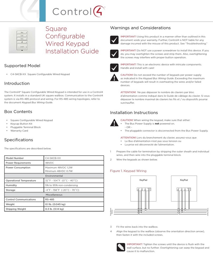
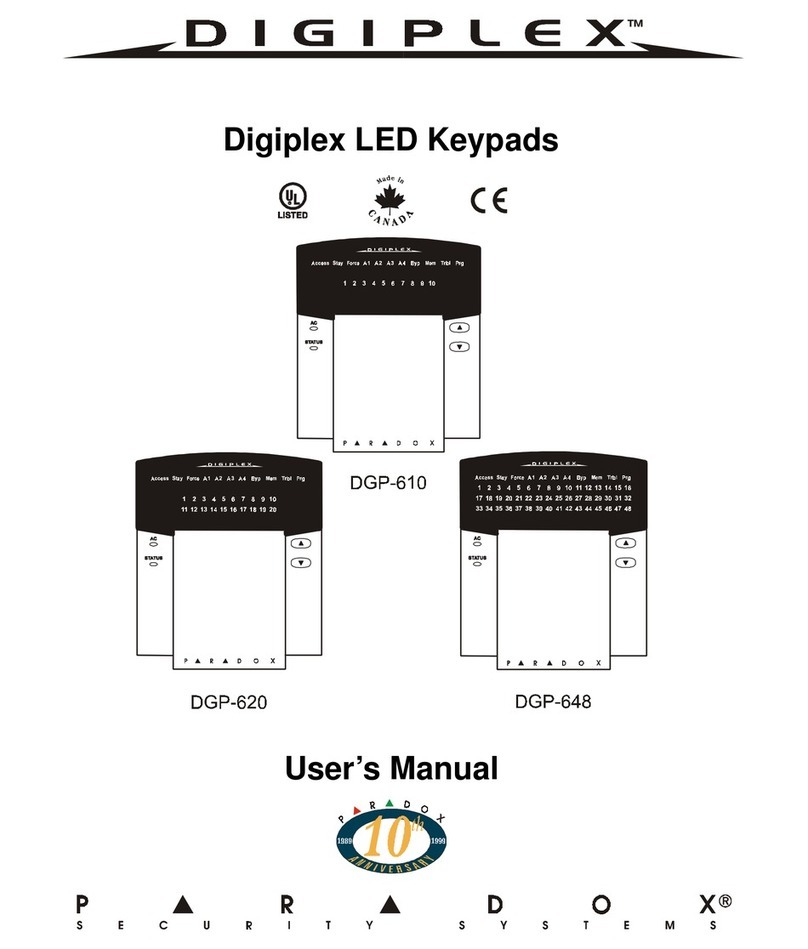
Bentel Security CLASSIKA Series User manual

MADE
IN
ITALY
ISO 9001
9105.BNT1 ISO 9001
IT-52587
ISO 14001
9191.BNT2 ISO 14001
IT-52588
OHSAS 18001
9192.BSEC OHSAS 18001
IT - 60983
Tastiere di controllo LED/LCD
LED/LCD Control Keypads
Teclados de control LED/LCD
Claviers de control LED/LCD

INTRODUZIONE
CLASSIKA Series è una serie di Tastiere per la gestione degli impianti antifurto realiz-
zaticoncentralidellaserieKyo Unit oppureconlecentraliKyo100,Kyo300 eKyo320
(revisione firmware 2.06 o successiva).
Queste istruzioni illustrano l'installazione, la programmazione ed il collegamento
della Tastiera; per maggiori informazioni sul suo uso con le centrali elencate sopra,
leggere le istruzioni fornite con le centrali stesse.
La tastiera è disponibile in 2 versioni:
BKB-LCD – Tastiera con display LCD di 2 righe per 16 caratteri;
BKB-LED – Tastiera con 16 LED.
In queste istruzioni si userà il termine generico "Tastiera" per fare riferimento ad
entrambe le versioni; il termine "Tastiera LCD" per fare riferimento alla versione
BKB-LCD, il termine "Tastiera a LED" per fare riferimento alla versione BKB-LED.
La Tastiera è predisposta per il funzionamento con il nuovo protocollo di comuni-
cazione BPI-2 ed è predisposta anche per il montaggio a parete o su scatole tipo
503 o equivalenti: inoltre essa è dotata di dispositivi per la rilevazione e la segna-
lazione dei tentativi di manomissione (antisabotaggio ed antistrappo).
CARATTERISTICHE TECNICHE
DESCRIZIONE Min. Tipica Max
Alimentazione 10 Vcc 12 Vcc 13,8 Vcc
Corrente assorbita (*) 20mA 40mA 60 mA
Temperatura di funzionamento +5° ÷ +40 °C
Dimensioni L x A x P (mm) 144,5 x 115 x 27,5
(
*) - La corrente assorbita varia in base alle condizioni di funzionamento.
I
l valore minimo si riferisce al funzionamento in condizioni di riposo e
a
ssenza di illuminazione; il valore massimo si riferisce al funzionamento
c
on la tastiera illuminata.
IDENTIFICAZIONE DELLE PARTI
Nella figura 1 è riportato il disegno della tastiera LCD (la Tastiera a LED differisce
solo per la presenza dei LED al posto del display LCD) con le varie parti numerate:
i numeri in grassetto riportati tra parentesi quadre [ ] indicati nei successivi para-
grafi fanno riferimento alle parti riportate in Fig. 1: tali parti vengono descritte nella
tabella seguente:
Fondo per il montaggio a parete
Ganci a scatto per il bloccaggio del coperchio
Morsettiera per i collegamenti
Fori per il fissaggio su scatola modello 503 o equivalente
Apertura per il passaggio dei cavi di collegamento
Fori per il fissaggio a parete
Ganci per il fissaggio del coperchio
Aperture per la rimozione del coperchio
Setto rimovibile per il passaggio dei cavi canalizzati a vista.
Coperchio
Tassello antistrappo
Perno conduttivo per la chiusura del contatto antisabotaggio
Sportello
INSTALLAZIONE
Per l'installazione della Tastiera a parete, procedere come descritto di seguito
(vedere fig. 1 in fondo alle istruzioni).
1) Inserire un cacciavite a taglio nelle aperture [8] per sbloccare i ganci [2], quindi
rimuovere il coperchio [10] avendo cura che la morsettiera sia sfilata delicatamente;
2) Passare i cavi di collegamento attraverso l’apertura [5].
3a) Seèprevistoilmontaggioa parete, utilizzareifori [6] peril fissaggio delfondo
[1] al muro;
3b) Se è previsto il montaggio su una scatola mod. 503 o equivalente, utilizzare
i fori [4] per il fissaggio del fondo [1];
4) Fissare il tassello per antisabotaggio [11];
5) Eseguire i collegamenti della tastiera utilizzando la morsettiera [3];
6) Riposizionare il coperchio [10] agganciandolo prima ai ganci [7], quindi bloc-
carlo con una leggera pressione fino a far scattare i ganci [2].
DESCRIZIONE DEI MORSETTI
In questo paragrafo sono descritti sinteticamente i morsetti della tastiera. Nella
tabella di questo paragrafo vengono adottate le seguenti convenzioni:
¾la colonna M. mostra le sigle dei morsetti;
¾la colonna DESCRIZIONE mostra una descrizione sintetica del morsetto;
¾lacolonnav (V) mostra la tensione, in volt, presente sul morsetto corrispondente
(il simbolo “–” indica che non è possibile specificare un valore di tensione);
¾lacolonnaI(A)mostralacorrentemassima,inampere,chepuòcircolaresulmorsetto
corrispondente (il simbolo “–” indica che non è possibile specificarne un valore).
M. DESCRIZIONE v (V) I (A)
+Alimentazione: positivo 13,8 (*)
CComando – –
RRisposta – –
– Alimentazione: negativo 0–
(
*) - Vedere le caratteristiche tecniche.
PROGRAMMAZIONE
NOTA - Alla prima alimentazione, la tastiera entra AUTOMATICAMENTE nella
fase di programmazione e ci rimane fino a quando non viene programmato
l’indirizzo.
NOTA - Per evitare programmazioni accidentali o non autorizzate, l’accesso
allaprogrammazioneèpossibileSOLOseètrascorsamenodi mezz’ora dall’ul-
timo reset BPI inviato dalla centrale. Il reset BPI si verifica ogni volta che la
Tastiera viene alimentata e ogni volta che si esce dal menu installatore.
Per programmare la Tastiera procedere come descritto in questo paragrafo.
Tenere presente che ad ogni pressione del tasto ENTER si confermano i valori
inseriti e si avanza al passo successivo mentre ad ogni pressione del tasto ESC si
annullano i valori inseriti e si torna indietro di un passo (fino ad uscire dalla fase
di programmazione).
NOTA - La tastiera esce dalla fase di programmazione trascorso un minuto
dalla pressione dell’ultimo tasto.
¾Per impostare gli indirizzi usare i tasti Ce Dper scorrere gli indirizzi disponibili
oppure, digitare l'indirizzo sulla tastiera:
¾per inserire gli indirizzi maggiori di 9, digitare la seconda cifra dell'indirizzo
entro 1 secondo dalla prima;
¾se si inserisce un indirizzo sbagliato, aspettare almeno 2 secondi prima di pro-
vare di nuovo.
Sulla Tastiera LCD l'indirizzo impostato viene mostrato dagli ultimi due caratteri
della riga superiore del display.
Sulla Tastiera a LED l'indirizzo impostato viene mostrato dalle spie da 1 a 16:
¾la spia accesa indica che è stato impostato l'indirizzo corrispondente;
¾la spia lampeggiante indica che è stato impostato l'indirizzo 16 + numero della spia.
Per esempio, se la spia 9 è accesa, significa che è stato selezionato l'indirizzo n.
9; se la spia 9 lampeggia, significa che è stato selezionato l'indirizzo n. 25 (16 + 9).
Durante tutti i passi della programmazione, la riga inferiore del display della Tastie-
ra LCD mostra tutti i tasti che, di volta in volta, possono essere usati.
PROGRAMMAZIONE TASTIERA LCD
Per la programmazione della Tastiera LCD, procedere come descritto di seguito.
1) Premere e mantenere premuti i tasti 1e OFF per almeno 3 secondi trascorsi i
quali si entra nella fase di programmazione: il display visualizzerà nella prima riga
il nome della tastiera (CLASSIKA) e l’indirizzo attuale, come ad esempio, 1).
2) Programmazione dell’INDIRIZZO - Impostare l’indirizzo della tastiera (da 1a
32), quindi premere ENTER per confermare l'indirizzo visualizzato oppure preme-
re ESC per annullare la modifica ed uscire dalla fase di programmazione.
ATTENZIONE-Prima di rimuovereilcoperchiodellatastiera,APRIRECOMPLETAMENTELOSPORTELLINO.
NON collegare la Tastiera al bus quando questo è alimentato; se ciò non fosse possibile collegare i morsetti del bus nel seguente ordine: –, +, R, C.
II
II
IITALIANO

PROGRAMMAZIONE TASTIERA LED
Per la programmazione della Tastiera LED, procedere come descritto di seguito.
1) Premere e mantenere premuti i tasti 1e OFF per almeno 3 secondi trascorsi i
quali si entra nella fase di programmazione.
2) Programmazionedell’INDIRIZZO-IlLEDIaccesoindicachesistaprogram-
mando l’indirizzo della tastiera.
Programmare l'indirizzo desiderato per la Tastiera (da 1a 8), quindi
premere ENTER per confermare oppure premere ESC per annullare ed uscire
dalla fase di programmazione.
LUMINOSITÀ, CONTRASTO E VOLUME
Per regolare la luminosità, il contrasto ed il volume del buzzer interno, procedere
come descritto di seguito:
LUMINOSITÀ
È possibile regolare la luminosità dei tasti e, solo per la versione LCD, anche
quella della retroilluminazione del display.
È possibile regolare la luminosità a riposo e quella in funzione (la luminosità a
riposo si intende quella che la tastiera assume dopo 10 secondi di inattività).
Per regolare la luminosità in funzione, procedere come descritto di seguito:
1a) Per aumentare la luminosità, premere e mantenere premuto il tasto Afino a
quando non si ottiene il livello desiderato:
1b) Per diminuire la luminosità, premere e mantenere premuto il tasto Bfino a
quando non si ottiene il livello desiderato.
2) Premere il tasto OFF per regolare la luminosità a riposo:
3a) Per aumentare la luminosità, premere e mantenere premuto il tasto Afino a
quando non si ottiene il livello desiderato:
3b) Per diminuire la luminosità, premere e mantenere premuto il tasto Bfino a
quando non si ottiene il livello desiderato.
4) Premere il tasto ON per regolare la luminosità in funzione e tornare al passo n.
1a) oppure,
premere il tasto ENTER per confermare i livelli scelti oppure,
attendere qualche secondo che la tastiera torni nello stato di riposo.
CONTRASTO (solo per la versione LCD)
Per regolare il contrasto del display LCD, procedere come descritto di seguito:
1a) Per aumentare il contrasto, premere e mantenere premuto il tasto Dfino a
quando non si ottiene il livello desiderato:
1b) Per diminuire il contrasto, premere e mantenere premuto il tasto Cfino a
quando non si ottiene il livello desiderato.
2) Per confermare il livello scelto, premere il tasto ENTER (oppure attendere
qualche secondo che la tastiera torni nello stato di riposo).
VOLUME
Per regolare il volume del buzzer interno, procedere come descritto di seguito:
1) Premere e mantenere premuto il tasto ESC: il buzzer interno comincerà ad
emettere una serie di beep per dar modo all’operatore di ascoltarne il livello so-
noro in tempo reale.
NOTA - Il buzzer emetterà comunque una serie di beep ad un volume minimo
anche se era stato regolato a zero.
2a) Per aumentare il volume, premere più volte o mantenere premuto il tasto A
fino a quando non si ottiene il livello desiderato.
2b) Perdiminuire il volume, premere più volte o mantenere premuto il tastoBfino
a quando non si ottiene il livello desiderato.
3) Per confermare il livello scelto, premere il tasto ENTER (oppure attendere
qualche secondo che la tastiera torni nello stato di riposo).
Il contenuto di questo manuale può essere soggetto a modifiche senza preavviso e non rappresenta un impegno
da parte della BENTEL SECURITY srl.
COLLEGAMENTI
La tastiera va collegata al bus BPI della centrale come descritto nelle istruzioni
fornite con la centrale stessa (vedi anche Fig. 2).
Questa Tastiera supporta SOLO il Livello BPI a 12 V.

GG
GG
GENGLISH
INTRODUCTION
CLASSIKA Series is a series of Keypads controlling anti-burglary circuits which
have been realized with Kyo Unit series control panels or with Kyo100, Kyo300
and Kyo320 (firmware 2.06 or higher) control panels.
These instructions refer to the installation, programming and connection of the
Keypad; for further information on its use with the above mentioned control panels,
read the instructions provided with the said panels.
The keypad is available in 2 versions:
BKB-LCD - Keypad with an LCD display of 2 lines and 16 digits;
BKB-LED - Keypad with 16 LED.
Inthese instructions thegeneric term "Keypad"is used torefer to bothversions; the
term"LCDKeypad"torefer totheBKB-LCD version,theterm"LEDKeypad"torefer
to the BKB-LED version.
The outputs are of open-collector (O.C.) type or rather floating or connected to Earth.
The Keypad is planned to work with the new communication protocol BPI-2.
The Keypad is provided for flush or surface mounting, or on type 503 boxes.
The Keypad is provided with devices for the detection and raising of an alarm
against tampering and snatching attempts.
TECHNICAL SPECIFICATIONS
DESCRIPTION Min. TYPE Max
Power Supply 10 Vcc 12 Vcc 13.8 Vcc
Current Draw (*) 20 mA 40 mA 60 mA
Temperature Range +5° ÷ +40 °C
Dimensions W x H x D (mm) 144.5 x 115 x 27.5
(
*) - The current draw varies acc. to working conditions. The min. value
r
efers to work at rest conditions and absence of light; the max. refers to
w
ork with lit keypad.
IDENTIFICATION OF PARTS
Figure 1 show the LCD Keypad designs (the LED Keypad differs only in a LED
insteadof an LCDdisplay) with its variousparts numbered: thenumbersin boldface
shown in square brackets [ ] in the followign paragraphs refer to the parts shown
in Fig. 1 and are being described in the following table:
Base for flush mounting
Clips to block the frontplate
Terminal board for connections
Anchor screw holes for mounting on model 503 box or similar
Cable entry
Anchor screw holes for flush mounting
Clips for fixing of frontplate
Openings for the removal of the frontplate
Removable partition for the passing of visible channelled wires
Frontplate
Anti-snatch rawlplug
Conductive pin for closing of anti-tamper contact
Flip
SURFACE MOUNTING
For surface installation of the Keypad, follow the procedure described below
(see fig. 2 at the end of the instructions):
1) Insert a sharp screwdriver into openings [8] to release the hooks [2], then
remove the cover [10] taking care to slide the terminal board out delicately;;
2) Pass the connection wires through the opening [5];
3a) If it is to be flush mounted, use the holes [6] to fix the base [1] to the wall;
3b) If it is to be mounted on a model 503 box or similar, use the holes [4] to fix
to the base [1];
4) Fix the anti-tamper plug [11];
5) Make the keypad connections using the terminal board [3];
6) Repositionthefrontplate [10] byfirsthookingitto theclips[7],thenbyblocking
it by applying light pressure until the clips are released [2].
DESCRIPTION OF THE TERMINALS
This paragraph synthetically describes the Keyboard terminals. The table in
this paragraph uses the following terms:
¾column M. gives the abbreviations of the terminals;
¾column DESCRIPTION gives a synthetic description of the terminal;
¾column v (V) gives the voltage, in volts, as on the corrisponding terminal (the
symbol "–" indicates that it is not possible to specify a voltage value);
¾column I (A) gives the maximum current, in ampere, which could move along
on the corrisponding terminal (the symbol "–" indicates that it is not possible to
specify any value).
M. DESCRIPTION v (V) I (A)
+Positive power supply 13.8 (*)
CCommand – –
RResponse – –
–Negative power supply 0 –
(
*) - See the technical specifications.
PROGRAMMING
NOTE - The first time it is switched on, the keypad will AUTOMATICALLY enter
itsprogrammingphase,andwillremaininthatmodeuntiltheaddresshasbeen
programmed.
NOTE - To avoid any accidental or unauthorized programming, access to
programmingisONLYpossibileiflessthan halfan hour haspassed fromthe
last BPI reset effected from the control panel. BPI resetting occurs every
time the Keypad is powered up, and on exiting from the installer menu.
To program the Keypad, follow the procedure described in this paragraph.
Remember that pressing the ENTER key confirms the input values and a move
forwardismadetothenextstepwhile eachpressingoftheESC keycancelsthe
input values and a step backwards is made (up to exiting the programming
phase).
NOTE - The keypad exits the programming phase one minute after the last
button was pressed.
¾To set the addresses, use keys Cand Dto scroll through the available
addresses, or key the address into the Keypad:
¾to enter addresses greater than 9, key the second digit of the address within 1
second of the first;
¾if you enter an incorrect address, wait at least 2 seconds before trying again.
OntheLCDkeypad,theaddressthathasbeensetisshownbythelasttwocharacters
of the top line of the display.
On the LED Keypad, the address set is shown by LEDs 1 to 16:
¾whenan LED lights up, it indicates that the corresponding address has been set;
¾whenan LED flashes, itindicatesthat the address which hasbeenset is 16 + the
number of the LED.
For example, if LED 9 is lit, it indicates that address no. 9 has been selected; if LED
9 flashes, it indicates that address no. 25 (16 + 9) has been selected.
During all the steps involved in programming, the bottom line of the LCD Keypad
display shows all the keys which can be used at any given time.
PROGRAMMING THE LCD KEYPAD
1) Press and keep pressed the keys 1and OFF for at least 3 seconds after which
the programming phase starts: the display will show in the first line the name of the
keypad (CLASSIKA) and the actual address (for example,1).
2) Programming the ADDRESS - Set the address ofthe keyboard (from 1 to32),
then press ENTER to confirm or press ESC to cancel the change and exit
programming.
PROGRAMMING THE LED KEYPAD
For programming the LED Keypad, follow the procedure described below.
1) Press and keep pressed the keys 1and OFF for at least 3 seconds after which
the programming phase starts.
2) ProgrammingtheADDRESS-ThelitLEDIindicatesthatthekeypadaddress
is being programmed.
Program the required address for the Keypad (from 1to 8), then press ENTER to
confirm or press ESC to cancel and exit programming.
CAUTION-Before removing thekeypadcover,OPENTHEFLIPCOMPLETELY.
WARNING - DO NOT connect the Keypad to the bus when the bus is live; if this is not possible connect the bus terminals in the following order: -, +, R, C.

BENTEL SECURITY srl reserves the right to modify the technical specifications of this product without prior notice.
BRIGHTNESS, CONTRAST AND VOLUME
To adjust the brightness, the contrast and the volume of the internal buzzer, follow
the procedure described below:
BRIGHTNESS
It is possible to adjust the brightness of the keys and, on the LCD version only, also
the brightness of the backlighting of the display.
Itis possible to adjust the inactive and the active brightness (theinactive brightness
is the brightness to which the keypad reverts after 10 seconds of inactivity.
To adjust the active brightness, follow the procedure described below:
1a) To increase the brightness, press and keep pressed key Auntil the desired
level is obtained:
1b) To lower the brightness, press and keep pressed key Buntil the desired level
is obtained:
2) Press the OFF key to adjust the inactive brightness:
3a) To increase the brightness, press and hold down key Auntil the desired
brightness is reached:
3b) To reduce the brightness, press and hold down key Buntil the desired
brightness is reached:
4) Pressthe ON keyto adjust the activebrightnessand return to step1a),or press
the ENTER key to confirm the chosen levels, or
wait a few seconds for the keypad to return to the inactive state.
CONTRAST (only for the LCD version)
To adjust the contrast of the LCD display, follow the procedure described below:
1a) Toincrease the contrast, pressand keep pressedkey Duntilthedesired level
is obtained.
1b) To lower the contrast, press and keep pressed key Cuntil the desired level
is obtained.
2) Toconfirm thechosen level,press theENTER key (orwait afew secondsfor the
keypad to return to the inactive state).
VOLUME
To adjust the volume of the internal buzzer, follow the procedure described below:
1) Press and keep pressed the ESC key; the internal buzzer will start sounding a
series of beeps in such manner that the operator could hear the sound level in real
time.
NOTE- The buzzer will still emit a seriesof sound alerts at extremely low volu-
me, even if it has been set to zero.
2a) To increase the volume, press key A for a number of times and/or keep it
pressed until the desired level is obtained:
2b) To lower the volume, press più volte and/or keep pressed key Buntil the
desired level is obtained.
3) Toconfirm thechosen level,press theENTER key (orwait afew secondsfor the
keypad to return to the inactive state).
CONNECTIONS
The keypad should be connected to the BPI bus of the control panel as described
in the instructions delivered with the same control panel (see Fig. 2).
This Keypad supports ONLY a 12 V BPI level.

EE
EE
EESPAÑOL
INTRODUCCIÓN
CLASSIKASeriesesunaseriedeTecladosparalagestióndeinstilacionesantirrobo
fabricadascon centralesdela serie Kyo Unit, Kyo100, Kyo300 y Kyo320(revisión
firmware 2.06 o superior).
Estas instrucciones detallan la instalación, la programación y la conexión del
Teclado; para mayor información sobre su uso con las centrales descriptas arriba,
leer las instrucciones que acompañan las centrales.
El teclado se encuentra disponible en 2 versiones:
BKB-LCD - Teclado con display LCD de 2 líneas 16 caracteres;
BKB-LED - Teclado con 16 LED.
En estas instrucciones se utilizará el término genérico "Teclado" para referirse a
ambas versiones; el término "Teclado LCD" para referirse a la versión BKB-LCD,
el término "Teclado de LED" para referirse a la versión BKB-LED.
El teclado está preparado para funcionar con el nuevo protocolo de comunicación
BPI-2.
El Teclado está dotado de dispositivos para detectar y señalar intentos de
forzamiento (antisabotaje y anti-arrancamiento)
CARACTERÍSTICAS TÉCNICAS
DESCRIPCIÓN Min. Típica Máx.
Alimentación 10 Vcc 12 Vcc 13,8 Vcc
Corriente absorbida (*) 20 mA 40 mA 60 mA
Temperatura de funcionamiento +5° ÷ +40 °C
Dimensiones Lx A x P (mm) 144,5 x 115 x 27,5
(
*) - La corriente absorbida cambia en función de las condiciones de
f
uncionamiento. El valor mínimo se refiere al funcionamiento en condicione
s
d
e reposo y ausencia de iluminación; el valor máximo se refiere al
f
uncionamiento con teclado iluminado.
IDENTIFICACIÓN DE LAS PARTES
En la figura 1 se indican los dibujos del teclado LCD (el teclado de LED difiere sólo
por la presencia de los LED en lugar del display LCD) con las diferentes partes
numeradas: los números en negrita indicados entre corchetes [ ] indicados en los
párrafos posteriores se refieren a las partes indicadas en las Fig. 1 y se describen
en la siguiente tabla:
Fondo para el montaje a la pared
Ganchos de salto para el bloqueo de la tapa
Bornera para las conexiones
Orificios para fijar en caja modelo 503 o equivalente
Abertura para el paso de cables de conexión
Fondo para el montaje a la pared
Ganchos para la fijación de la tapa
Aberturas para quitar la tapa
Divisor extraíble para el paso de cables canalizados a la vista
Tapa
Taco Anti-arrancamiento
Perno conductor para el cierre del contacto antisabotaje
Portezuela
INSTALACIÓN EN LA PARED
Para la instalación del teclado en la pared, realizar cuanto se describe a
continuación (ver Fig. 2 al final de las instrucciones).
1) Introducir con un destornillador plano en las aberturas [8] para desbloquear
los ganchos [2], quitar la tapa [10] teniendo cuidado que la bornera se quite con
delicadeza;
3a) Si se prevé el montaje a la pared, utilizar [6] para fijar el fondo [1] a la pared;
3b) Siseprevé elmontaje enuna cajamod. 503o equivalente,utilizar losorificios
[4] para fijar el fondo [1];
4) Fijar en taco anti-arrancamiento [11];
5) Realizar las conexiones del teclado utilizando la bornera [3];
6) Volver a colocar la tapa [10] enganchándola primero a los ganchos [7], luego
bloquearla con una leve presión hasta que salten los ganchos [2].
ATENCIÓN-Antesde quitar latapa delteclado,ABRIR COMPLETAMENTE LAPORTEZUELA.
ATENCIÓN - NO conectar el Teclado al bus cuando está siendo alimentado, si esto no fuese posible, conectar los bornes del bus en el siguiente orden: -, +, R, C.
DESCRIPCIÓN DE LOS BORNES
En este párrafo se describen de forma sintética los bornes de Teclados. En la tabla
de este párrafo se adoptan las siguientes convenciones:
¾La columna M. muestra las siglas de los bornes
¾La columna DESCRIPCIÓN muestra una descripción sintética del borne
¾La columna v (V) muestra la tensión en voltios, presente en el borne
correspondiente (el símbolo "–" indica que no es posible especificar un valor de
tensión)
¾La columna I (A) muestra la corriente máxima, en amperes que puede circular
en el borne correspondiente (el símbolo "–" indica que no es posible especificar
un valor).
M. DESCRIPCIÓN v (V) I (A)
+Alimentación: positivo 13,8 (*)
Cmando – –
RRespuesta – –
– Alimentación:negativo 0–
(
*) - Vease las características técnicas
PROGRAMACIÓN
NOTA - En la primera conexión, el teclado entra AUTOMÁTICAMENTEenlafase
de programación y permanece allí hasta que se programa la dirección.
NOTA - Para evitar programaciones accidentales o no autorizadas, el acceso
ala programaciónes posibleSOLAMENTE siha pasadomenos demedia hora
delúltimo ajuste BPI enviado por la central. El ajuste BPI se produce cada vez
que el teclado es conectado y cada vez que se sale del menú instalador.
Para programar el teclado proceder como se describe en este párrafo.
Se debe tener presente que con cada presión de la tecla ENTER se confirman los
valores programados y se pasa al paso siguiente mientras en cada presión de la
tecla ESC se anulan los valores introducidos y se vuelve atrás un paso (hasta salir
de la fase de programación).
NOTA - El teclado sale de la fase de programación un minuto después de
haber presionado la última tecla.
¾Para programar las direcciones utilizar las teclas Cy Dpara pasar todas las
direcciones disponibles o bien digitar la dirección en el teclado:
¾para introducir las direcciones mayores de 9, digitar la segunda cifra de la
dirección dentro de los 1 segundo de la primera;
¾si se introduce una dirección errónea, esperar por lo menos 2 segundos antes
de probar otra vez.
En el teclado LCD la dirección programada es mostrada por los últimos dos
caracteres de la línea superior del display.
En elteclado deLED ladirección programadaes mostradaporlos indicadores 1a 16:
¾el indicador encendido indica que ha sido programada la dirección
correspondiente;
¾el indicador centelleante indica que ha sido programada la dirección 16 +
número del indicador.
Por ejemplo, si el indicador 9 está encendido, significa que ha sido seleccionada
la dirección n° 9; si el indicador 9 centellea, significa que ha sido seleccionada la
dirección n° 25 (16 + 9).
En todos los pasos de la programación, la línea inferior del display del teclado LCD
muestra todas las teclas que pueden ser utilizadas.
PROGRAMACIÓN DEL TECLADO LCD
1) Presionar y mantener presionadas las teclas 1y OFF durante por lo menos 3
segundos, pasados los cuales se entra en la fase de programación: el display
mostrará en la primera línea el nombre del teclado (CLASSIKA) y la dirección
actual (por ejemplo: 1).
2) Programación de la DIRECCIÓN - Programar la dirección del teclado (de 1a
32)yluegopresionarENTER paraconfirmarladirecciónvisualizadaobienpresionar
ESC para anular y salir de la programación..

BENTEL SECURITY srl se reserva el derecho a modificar las especificaciones técnicas de este producto sin previo aviso
PROGRAMACIÓN DEL TECLADO LED
1) Presionar y mantener presionadas las teclas 1y OFF durante por lo menos 3
segundos, pasados los cuales se entra en la fase de programación
2) Programación de la DIRECCIÓN - El LED Iencendido indica que se está
programando la dirección del teclado.
Programarla dirección deseada para el Teclado (de 1a 8), luego presionar ENTER
para confirmar o bien presionar ESC para anular y salir de la programación.
LUMINOSIDAD, CONTRASTE Y VOLUMEN
Para regular la luminosidad, el contraste y el volumen del buzzer interno, realizar
el procedimiento descrito a continuación:
LUMINOSIDAD
Se puede regular la luminosidad de las teclas y, sólo para la versión LCD, también
la iluminación posterior del display.
Se puede regular la luminosidad en reposo y aquella en función (la luminosidad
en reposo es la que el teclado asume pasados de 10 segundos de inactividad).
Para regular la luminosidad en función, proceder como se describe a continuación:
1a) Para aumentar la luminosidad, presionar y mantener presionada la tecla A
hasta que se consigue el nivel deseado:
1b) Para disminuir la luminosidad, presionar y mantener presionada la tecla B
hasta que se consigue el nivel deseado:
2) Presionar la tecla OFF para regular la luminosidad en reposo:
3a) Para aumentar la luminosidad, presionar y mantener presionada la tecla A
hasta que se consigue el nivel deseado:
3b) Para disminuir la luminosidad, presionar y mantener presionada la tecla B
hasta que se consigue el nivel deseado:
4) Presionar la tecla ON para regular la luminosidad en función y volver al paso
n°1a) o bien, presionar la tecla ENTER para confirmar los niveles elegidos o bien,
esperar algunos segundos que el teclado vuelva al estado de reposo.
CONTRASTE (solamente para la versión LCD)
Para programar el valor de contraste del teclado, realizar el siguiente
procedimiento:
1a) Para aumentar el contraste, presionar y mantener presionada la tecla D
hasta que se consigue el nivel deseado:
1b) Paradisminuir el contraste, presionar y mantener presionada la tecla Chasta
que se consigue el nivel deseado:
2) Para confirmar el nivel elegido, presionar la tecla ENTER (o bien esperar
algunos segundos que el teclado vuelva al estado de reposo).
VOLUMEN
Para regular el volumen del buzzer interno, proceder como se describe a
continuación:
1) Presionar y mantener presionada la tecla ESC; el buzzer interno comenzará a
emitir una serie de beep para que el operador escuche el nivel sonoro en tiempo
real.
NOTA-Elbuzzeremitirá una seriedebeeps con unvolumenmínimo inclusosi
ya había sido regulado a cero.
2a) Para aumentar el volumen, presionar varias veces y/o mantener presionada
la tecla Ahasta que se consigue el nivel deseado:
2b) Para disminuir el volumen, presionar varias veces y/o mantener presionada
la tecla Bhasta que se consigue el nivel deseado:
3) Para confirmar el nivel elegido, presionar la tecla ENTER (o bien esperar
algunos segundos que el teclado vuelva al estado de reposo).
CONEXIONES
Elteclado seconecta al busBPI delacentral comose describe enlas instrucciones
suministradas con la central (Fig. 2).
Este teclado soporta SÓLO el nivel BPI a 12 V.

FF
FF
FFRANÇAIS
ATTENTION-Avantderetirerlecouvercleduclavier,OUVRIRCOMPLÈTEMENTLEVOLET.
ATTENTION - NE PAS brancher le Clavier au bus lorsqu'il est alimenté ; brancher, dans la mesure du possible, les bornes du bus dans l'ordre suivant : -, +, R, C.
INTRODUCTION
CLASSIKA Series est une série de Claviers pour la gestion des installations antivol
réalisées avec des centrales de la série Kyo Unit ou bien avec les centrales
Kyo100, Kyo300 et Kyo320 (révision firmware 2.06 ou supérieure).
Ces instructions illustrent l'installation, la programmation et le branchement du
Clavier; pour de plus amples informations quant à son utilisation avec les centrales
citées plus haut, lire les instructions fournies avec celles-ci.
Le clavier est disponible en 2 versions :
BKB-LCD - Clavier avec écran LCD de 2 lignes de 16 caractères;
BKB-LED - Clavier avec 16 LED.
Dans ces instructions, le terme général " Clavier " sera utilisé pour se référer aux deux
versions; le terme " Clavier LCD " se réfèrera àla version BKB-LCD, le terme" Clavier
à LED " se réfèrera à la version BKB-LED.
Le Clavier est prédisposé pour le fonctionnement avec le nouveau protocole de
communicationBPI-2.
Le Clavier est doté de dispositifs pour la détection et la signalisation des tentatives
de violation (antisabotage et antidéchirure).
CARACTÉRISTIQUES TECHNIQUES
Description Min. Tipique Max
Alimentation 10 Vcc 12 Vcc 13,8 Vcc
Courant Absorbé (*) 20 mA 40 mA 60 mA
Température de fonctionnement +5° ÷ +40 °C
Dimensions L x H x P (mm) 144,5 x 115 x 27,5
(
*) - Le courant absorbé varie en fonction des conditions de marche.
L
a valeur minimum se réfère au fonctionnement en conditions de repos
e
t absence d'éclairage; la valeur maximum se réfère au fonctionnement
a
vec clavier éclairé.
IDENTIFICATION DES COMPOSANTS
Sur figure 1 sont reportés les dessins du clavier LCD (le Clavier à LED diffère
unique par la présence des LED au lieu de l'écran LCD) avec les différents
composants numérotés : les numéros en gras reportés entre parenthèses carrées
[ ] indiqués dans les paragraphes suivants font référence aux composants reportés
sur Fig. 1 et sont décrits dans le tableau suivant :
Fond pour le montage au mur
Crochets clipsés pour le blocage du couvercle
Bornier pour les branchements
Trous pour la fixation sur boîte modèle 503 ou équivalent
Ouverture pour le passage des câbles de branchement
Trous pour le montage au mur
Crochets pour la fixation du couvercle
Ouverture pour l'enlèvement du couvercle
Cloison amovible pour le passage des câbles canalisés à vue
Couvercle
Cheville antidéchirure
Verrou conducteur pour la fermeture du contact antisabotage
Volet
INSTALLATION AU MUR
Pour l'installation du Clavier au mur, procéder tel qu'il est décrit ci-dessous:
1) Insérer un tournevis plat dans les ouvertures [8] pour débloquer les clips [2],
puis retirer le couvercle [10] en ayant soin d'enlever délicatement le bornier;
2) Passer les câbles de branchement à travers l'ouverture [5].
3a) Si vous avez prévu de monter l'appareil au mur, utiliser les trous [6] du fond
[1] au mur ;
3b) Sivous avezprévu demonter l'appareil surune boîtemod. 503ouéquivalent,
utiliser les trous [4] pour la fixation du fond [1].
4) Fixer la cheville anti-déchirure [11] ;
5) Réaliser les branchements du clavier en utilisant le bornier [3] ;
6) Repositionner le couvercle [10] en l'accrochant d'abord aux crochets [7], puis
le bloquer avec une légère pression jusqu'au blocage des crochets [2].
DESCRIPTION DES BORNES
Dans ce paragraphe, vous trouverez une description synthétique des bornes. Le
tableau de ce paragraphe est formé des conventions suivantes:
¾la colonne B. illustre les sigles des bornes ;
¾la colonne DESCRIPTION décrit synthétiquement la borne ;
¾lacolonnev(V)montrelatension,envolts,présente surlabornecorrespondante
(le symbole "–" indique qu'il n'est pas possible de spécifier une valeur de tension);
¾la colonne I (A) montre la courant maximum, en ampères, qui peut circuler sur
laborne correspondante (le symbole "–" indique qu'il n'est paspossibledespécifier
une valeur).
B. DESCRIPTION v (V) I (A)
+Alimentation : positif 13,8 (*)
CCommande – –
RRéponse – –
– Alimentation : négatif 0–
(
*) - Voir les caractéristiques techniques
PROGRAMMATION
NOTE - Lorsqu'il est alimenté pour la première fois, le clavier entre
automatiquement dans la phase de programmation et y reste jusqu'à ce que
l'adresse soit programmée.
NOTE - Pour éviter des programmations accidentelles ou non autorisées,
l'accès à la programmation est possible UNIQUEMENT si moins d'une demi-
heure s'est écoulée depuis la dernière réinitialisation BPI envoyée à la centra-
le.La réinitialisationBPI se vérifiera à chaquefois quele Clavier sera alimenté
et à chaque fois que l'on sortira du menu installateur.
Pour programmer le Clavier, procéder tel qu'il est décrit dans ce paragraphe.
Rappelez-vous qu'à chaque pression du bouton ENTER l'on confirme les valeurs
insérées et l'on avance à l'étape suivante alors que chaque pression du bouton
ESC annule les valeurs insérées et renvoie à l'étape précédente (jusqu'à la sortie
de la phase de programmation).
NOTE - Le clavier sort de la phase de programmation après une minute
d'inactivité des touches.
¾Pour configurer les adresses, utiliser les touches C et Dpour faire défiler les
adresses disponibles ou bien, taper l'adresse sur le clavier :
¾pour insérer des adresses supérieures au chiffre 9, taper le second chiffre de
l'adresse dans un délai de 1 seconde après le premier ;
¾en cas d'insertion d'une adresse erronée, attendre au moins 2 secondes avant
de réessayer à nouveau.
Sur le Clavier LCD l'adresse configurée est visible aux deux derniers caractères
de la ligne supérieure de l'écran.
Sur le Clavier à LED l'adresse configurée est visible aux voyants 1à 16:
¾le voyant allumé indique que l'adresse correspondante a été insérée ;
¾le voyant clignotant indique que l'adresse 16 + le numéro du voyant a été
configurée.
Par exemple, si le voyant 9 est allumé, cela signifie que l'adresse n.9 a été
sélectionnée; si le voyant 9 clignote, cela signifie que l'adresse n.25 (16 + 9) a été
sélectionnée.
Durant toutes les étapes de la programmation, la ligne inférieure de l'écran du
Clavier LCD affiche toutes les touches qui, à chaque fois, peuvent être utilisées.
PROGRAMMATION DU CLAVIER LCD
1) Appuyer et maintenir enfoncées les touches 1et OFF durant au moins 3
secondes. Vous entrerez ainsi dans la programmation : l'écran affichera sur la
première ligne le nom du clavier (CLASSIKA) et l'adresse actuelle (par exemple,
1).
2) Programmation de l'ADRESSE - Configurer l'adresse du clavier (de 1à 32)
puis appuyer sur ENTER pour confirmer l'adresse affichée ou bien appuyer sur
ESC pour annuler et sortir de la programmation.
PROGRAMMATION DU CLAVIER LED
Suivre les étapes suivantes pour la programmation:
1) Appuyer et maintenir enfoncées les touches 1 et OFF durant au moins 3
secondes. Vous entrerez ainsi dans la phase programmation;

BENTEL SECURITY srl se réserve le droit de modifier les spécifications techniques de ce produit sans préavis.
2) Programmation de l'ADRESSE -LaLED Iallumée indique que l'adresse du
clavier est en cours de programmation.
Programmerl'adresse souhaitée pourle Clavier (de 1à8) puis appuyersur ENTER
pourconfirmeroubien,appuyersur ESCpourannuleretsortirdelaprogrammation.
LUMINOSITÉ , CONTRASTE ET VOLUME
Pour régler la luminosité, le contraste et le volume du buzzer interne, suivre les
procédures décrites ci-dessous :
LUMINOSITÉ
Il est possible de régler la luminosité des touches et, uniquement pour la version
LCD, également le rétroéclairage de l'écran. Il est possible de régler la luminosité
au repos et celle en fonction (la luminosité est celle que le clavier adopte après 10
secondes d'inactivité).
Pour régler la luminosité en fonction, procéder tel qu'il est décrit ci-dessous:
1a) Pour augmenter la luminosité, appuyer et maintenir enfoncée la touche A
jusqu'à l'obtention du niveau souhaité:
1b) Pourdiminuerlaluminosité,appuyeretmaintenirenfoncéelatoucheBjusqu'à
l'obtention du niveau souhaité:
2) Appuyer sur la touche OFF pour régler la luminosité au repos:
3a) Pour augmenter la luminosité, appuyer et maintenir enfoncée la touche A
jusqu'à l'obtention du niveau désiré:
3b) Pourdiminuerlaluminosité,appuyeretmaintenirenfoncéelatoucheB jusqu'à
l'obtention du niveau désiré.
4) Appuyer sur la touche ON pour régler la luminosité en fonction et revenir à
l'étape n.1a) ou bien,
appuyer sur la touche ENTER pour confirmer les niveaux choisis ou bien,
attendre quelques secondes que le clavier revienne à son état de repos.
CONTRASTE (uniquement pour la version LCD)
Pour régler le contraste de l'écran LCD, procéder tel qu'il est décrit ci-dessous:
1a) Pour augmenter le contraste, appuyer et maintenir enfoncée la touche D
jusqu'à l'obtention du niveau souhaité :
1b) Pourdiminuerlecontraste, appuyeret maintenirenfoncée latoucheCjusqu'à
l'obtention du niveau souhaité :
2) Pourconfirmer leniveau choisi,appuyersur latouche ENTER (ou bienattendre
quelques secondes que le clavier revienne à son état de repos).
VOLUME
Pour régler le volume du buzzer interne, procéder tel qu'il est décrit ci-dessous:
1) Appuyer et maintenir enfoncée la touche ESC ; le buzzer interne commencera
à émettre une série de bips afin de permettre à l'opérateur d'en écouter le niveau
sonore en temps réel.
NOTE-L'alarmeémettraunesérie de bipsàunvolumeminimummême s'il elle
a été réglée sur zéro.
2a) Pouraugmenterlevolume,appuyeretmaintenirenfoncéelatoucheAjusqu'à
l'obtention du niveau souhaité :
2b) diminuer le volume, appuyer et maintenir enfoncée la touche Bjusqu'à
l'obtention du niveau souhaité :
3) Pourconfirmer leniveau choisi,appuyersur latouche ENTER (ou bienattendre
simplement quelques secondes afin que le clavier revienne à son état de repos).
BRANCHEMENTS
Le clavier doit être branché au bus BPI de la centrale tel que décrit dans les
instructions fournies avec la centrale (Fig. 2)
Ce clavier supporte UNIQUEMENT le niveau BPI à 12V.

Fig. 1 - Parti della tastiera LCD - LCD Keypad Parts - Partes CLASSIKA LCD - Composants de clavier CLASSIKA LCD
Fig. 2 - Collegamenti - Connections - Conexiones - Branchements
CLASSIKA
(LCD / LED)

Informations sur le recyclage
BENTEL SECURITY recomande à ses clients de jeter le materiel appareils usagés (centrales, detecteurs, sirènes et autres dispositifs)
de manière à protéger l'environnement.
Les methods possibles incluent la reutilisation de pieces ou de produits entiers et le recyclage de produits, composants, et/ou matériels.
Pour obtenir davantage d'informations, veuillez vous rendre sur le site : www.bentelsecurity.com/en/environment.htm
Directive sur la mise au rebut des appareils électriques et électroniques (WEEE)
En Union européenne, cette etiquette indique que ce produit ne doit pas être jeté avec les déchets ménagers.
Il doit être mis au rebut dans un centre de dépôt spécialisé pour un recyclage approprié.
Pour obtenir davantage d'informations, veuillez vous rendre sur le site:
www.bentelsecurity.com/en/environment.htm
FF
FF
FFRANÇAIS
Información sobre reciclado
BENTEL SECURITY recomienda a los clientes que desechen el hardware antiguo (centrales, detectores, Sirenas y otros dispositivos) ateniendo a las normas de
protección del ambiente.
Métodos a seguir incluyen el volver a utilizar las partes o productos enteros y el reciclado de componentes y materiales.
Si desea obtener información específica, visite la página: www.bentelsecurity.com/en/environment.htm
Directiva sobre el deshecho de material eléctrico y electrónico (WEEE)
En la Unión Europea, esta etiqueta indica que la eliminación de este producto no se puede hacer junto con el deshecho doméstico.
Se debe depositar en una instalación apropiada que facilite la recuperación y el reciclado.
Si desea obtener información específica, visite la página www.bentelsecurity.com/en/environment.htm
EE
EE
EESPAÑOL
Recycling information
BENTEL SECURITY recommends that customers dispose of their used equipments (panels, detectors, sirens, and other devices)
in an environmentally sound manner.
Potential methods include reuse of parts
or whole products and recycling of products, components, and/or materials.
For specific information see: www.bentelsecurity.com/en/environment.htm
Waste Electrical and Electronic Equipment (WEEE) Directive
In the European Union, this label indicates that this product should NOT be disposed of with household waste.
It should be deposited at an appropriate facility to enable recovery and recycling.
For specific information see:
www.bentelsecurity.com/en/environment.htm
GG
GG
GENGLISH
Informazioni sul riciclaggio
BENTEL SECURITY consiglia ai clienti di smaltire i dispositivi usati (centrali, rilevatori, sirene, accessori elettronici, ecc.) nel rispetto dell'ambiente. Metodi potenziali
comprendono il riutilizzo di parti o di prodotti interi e il riciclaggio di prodotti, componenti e/o materiali.
Per maggiori informazioni visitare il sito: www.bentelsecurity.com/it/ambiente.htm
Direttiva Rifiuti di apparecchiature elettriche ed elettroniche (RAEE WEEE)
Nell'Unione Europea, questa etichetta indica che questo prodotto NON deve essere smaltito insieme ai rifiuti domestici.
Deve essere depositato in un impianto adeguato che sia in grado di eseguire operazioni di recupero e riciclaggio.
Per maggiori informazioni visitare il sito: www.bentelsecurity.com/it/ambiente.htm
II
II
IITALIANO

ISTISBL3BKB 0.4 131009 P70
BENTEL SECURITY S.r.l.
-
Tel.: +39 0861 839060 - Fax: +39 0861 839065
Via Gabbiano,22 - Z.I. Santa Scolastica - 64013 CORROPOLI- TE - ITALY
www.bentelsecurity.com - infobentelsecurity@tycoint.com
This manual suits for next models
2
Table of contents
Languages:
Other Bentel Security Keypad manuals
Bentel Security
Bentel Security Absoluta T-Line Series User manual
Bentel Security
Bentel Security PREMIUM Series User manual

Bentel Security
Bentel Security MIA-S User manual
Bentel Security
Bentel Security Absoluta M-touch User manual

Bentel Security
Bentel Security ALISON/S User manual
Bentel Security
Bentel Security KYO 32 Owner's manual
