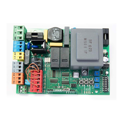
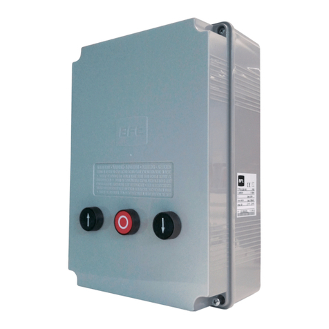
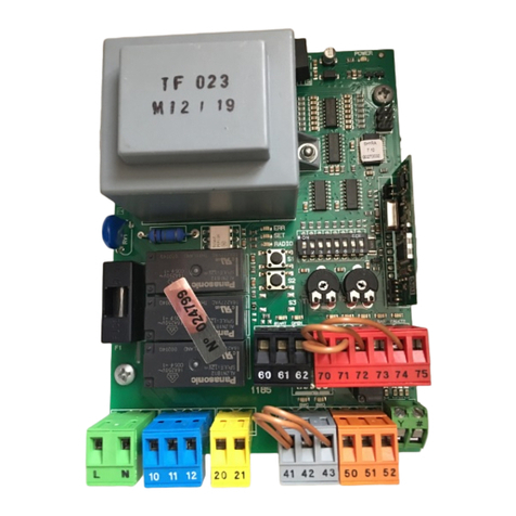
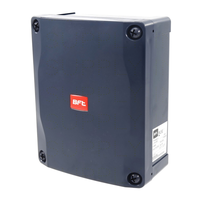
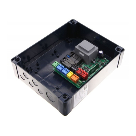
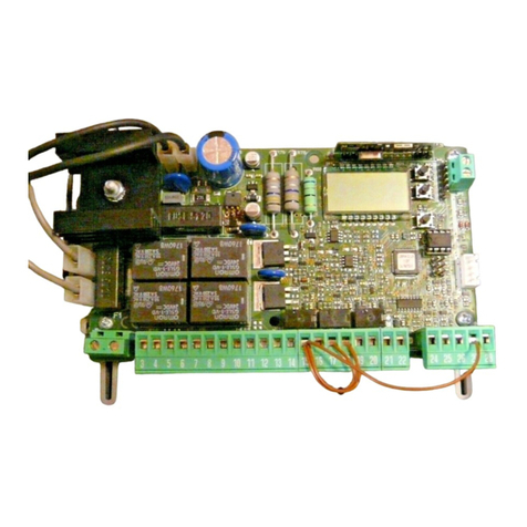
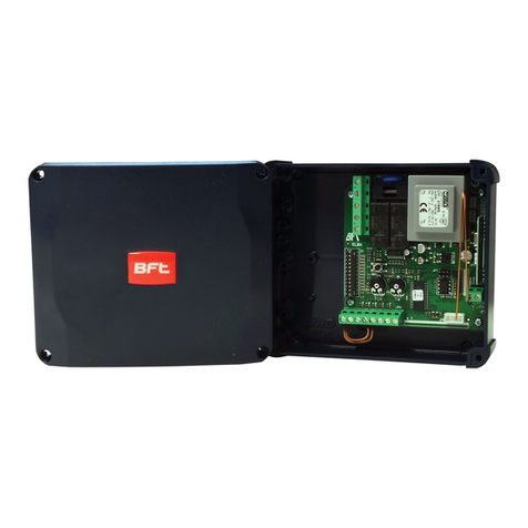
BFT HYDRA-N User manual

HYDRA-N
D811675 00100_02 29/05/09
ISTRUZIONI DI INSTALLAZIONE
INSTALLATION MANUAL
INSTRUCTIONS D’INSTALLATION
MONTAGEANLEITUNG
INSTRUCCIONES DE INSTALACION
INSTALLATIEVOORSCHRIFTEN HYDRA-N
Attenzione! Leggere attentamente le “Avvertenze” all’interno! Caution! Read “Warnings” inside carefully! Attention! Veuillez lire attentivement les Avertissements qui se trouvent à l’intérieur! Achtung! Bitte lesen Sie
aufmerksam die„Hinweise“ im Inneren! ¡Atención¡ Leer atentamente las“Advertencias” en el interior! Let op! Lees de “Waarschuwingen”tigre aan de binnenkant zorgvuldig!
QUADRO COMANDO
CONTROL PANEL
CENTRALE DE COMMANDE
SELBSTÜBERWACHENDE STEUERUNG
CUADRO DE MANDOS
BEDIENINGSPANEEL
8027908 351227
https://appceso.com

2 - HYDRA N
D811675 00100_02
https://appceso.com

ITALIANO ENGLISH FRANÇAIS ESPAÑOL
NEDERLANDS
DEUTSCH
INSTALLAZIONE VELOCE-QUICK INSTALLATION-INSTALLATION RAPIDE
SCHNELLINSTALLATION-INSTALACIÓN RÁPIDA - SNELLE INSTALLATIE
2
2
2
1 2 3 4 5 6 7 8 9 1011 12 13 14 15
22 20
2324
25
26
27
1921
161718
ANT.
ANT
SHIELD
PHEBE SQ
PHEBE SQ
S3
S2
S1
24V
25 W max
2829
N
L
0V
~
25V
~
HYDRA N - 3
D811675 00100_02
https://appceso.com

E
MEMORIZZAZIONE RADIOCOMANDO
MEMORIZING REMOTE CONTROLS
MÉMORISATION RADIOCOMMANDE
ABSPEICHERUNG DER FERNBEDIENUNG
MEMORIZACION DEL RADIOMANDO
MEMORISEREN AFSTANDSBEDIENINGD
RADIO
x 2
x 2
OK
PArAM
OK
OK
Fine - End - Fin
tasto nascosto-hidden button
-
touche cachee-verst.taste
rilascia-release-
relache -loslassen-suelte
tasto desiderato-
desider
button touche desiree-
gevue
taste-tecla deseada
Agg.start - Adjouter start -
zufuegstart - anad start
+ x 3
+
OK
8888
8888
REGOLAZIONE AUTOSET, ADJUSTING AUTOSET,
REGLAGE AUTOSET, EINSTELLUNG AUTOSET,
REGULACION AUTOSET,REGELING AUTOSET.
REGOLAZIONE VELOCITA’ RALLENTAMENTO
ADJUSTING SLOW-DOWN SPEED
RÉGLAGE DE LA VITESSE DE RALENTISSEMENT
EINSTELLUNG GESCHWINDIGKEIT VERLANGSAMUNG
REGULACIÓN VELOCIDAD DECELERACIÓN
AFSTELLING VERTRAGINGSSNELHEID
AUTO OPEN
OK
autoset
x 5
x 2
OK
PArAM
ESC
+
x 1
OK
vel. rall
tca
parm
vel. rall
prg
fine-end-fin
x 2
OK
OK
OK
x 1
x 2
+
+
OK
8888
+
OK
+
AUTO CLOSE
Collegamento di 1coppia fotocellule non vericate
Connection of 1 pair of non-tested photocells
Connexion d’1 paire de photocellules non vériées
Anschluss von einem Paar nicht überprüften Fotozellen
Conexión de 1 par fotocélulas no comprobadas
Aansluiting van 1 paar fotocellen anders dan trusted device
LOGICA test fotocellule OFF / Photocell test LOGIC OFF
LOGIQUE essai photocellules Désactivée / LOGIK Test Fotozellen OFF
LÓGICA prueba fotocélulas OFF / LOGICA test fotocellen OFF
F
DG
1
2
1
2
3
4
5
7
8
7
8
13
16
TX1 RX1
. . .3 . . .2 . . .1
. . .3 . . .2 . . .1
x 1
+
4 - HYDRA N
D811675 00100_02
https://appceso.com

1
2
3
4
5
6
7
8
9
10
11
12
13
14
15
16
JP1
SWC
MOT1
SWC
SWO
SWO
COMMON
COM
MOT-
MOT-
MOT+
MOT+
H
1
1 2 3 4 5 6 7 8 9 10 11 12 1314 15
22 20
2324
25
26
27
1921
161718
ANT.
ANT
SHIELD
PHEBE SQ
PHEBE SQ
S3
S2
S1
25W max.
24V ~(+)
24V ~(-)
VSafe +
VSafe -
PHOT
FAULT
SWO2
START
COM
STOP
+
SWO1
SWC1
COM
-
HYDRA N QSG
PHEBE N SQ
min 2,5 mm2
min 2,5 mm2
SCA
2CH
SWO1
-
+
SWC1
COM
1
2
3
4
5
6
7
8
9
10
11
12
13
14
15
16
JP1
SWC
SWC
SWO
SWO
COMMON
COM
MOT-
MOT-
MOT+
MOT+
1 2 3 4 5 6 7 8 9 1011 12 13 14 15
22 20
2324
25
26
27
1921
161718
ANT.
ANT
SHIELD
PHEBE SQ
PHEBE SQ
+
S3
S2
S1
25W max.
24V ~(+)
24V ~(-)
VSafe +
VSafe -
SWO2
2829
HYDRA N
QSG
PHEBE N SQ
1
2
3
4
5
6
7
8
9
10
11
12
13
14
15
16
JP1
SWC
SWC
SWO
SWO
COMMON
COM
MOT-
MOT-
MOT+
MOT+
PHEBE N SQ
min 2,5 mm2
min 2,5 mm2
min 2,5 mm2
min 2,5 mm2
SCA
2CH
MOT.1MOT.2
2x2.5*mm
2
+5x1.5mm
2
L-N-GND 3x1.5mm2
HYDRA N QSG
PHEBE N SQ
2x2,5*mm2
PHEBE N SQ
PHEBE N SQ
HYDRA N
2x2.5*mm2+5x1.5mm2
L-N-GND 3x1.5mm2
2x2,5*mm2
2x2.5*mm2
4x1.5mm2
PHEBE N SQ
L-N-GND 3x1.5mm2
PHEBE N
2x2.5*mm
2
4x1.5 mm
2
2x2,5*mm2
1
2
3
4
5
6
7
8
9
10
11
12
13
14
15
16
JP1
SWC
SWC
SWO
SWO
COMMON
COM
MOT-
MOT-
MOT+
MOT+
1 2 3 4 5 6 7 8 9 10 11 12 13 14 15
22 20
2324
25
26
27
1921
161718
ANT.
ANT
SHIELD
PHEBE SQ
PHEBE SQ
+
S3
S2
S1
25W max.
24V ~(+)
24V ~(-)
VSafe +
VSafe -
SWO2
2829
HYDRA N
PHEBE N SQ
min 2,5 mm2
min 2,5 mm2
SCA
2CH
MOT2
2
3
MOT.1
MOT.1
24 V 3W
Lock
24 V
24 V 3W
Lock
24 V
24 V 3W
Lock
24 V
*2,5mm210m max.
*2,5mm210m max.
*2,5mm210m max.
28
29
24V ~(-)
24V ~(+)
24V ~(-)
24V ~(+)
24V ~(-)
24V ~(+)
PHOT
FAULT
START
COM
STOP
PHOT
FAULT
START
COM
STOP
HYDRA N - 5
D811675 00100_02
https://appceso.com

J
I
Programmeerbare Universele Palmtop
UNIDA
1
2
1
2
3
4
5
7
8
7
8
13
16
TX1 RX1
1-PHOT
1
2
1
2
3
4
5
9
10
7
8
13
16
TX1 RX1
17
1-PHOT
1
2
1
2
3
4
5
9
10
9
10
7
8
13
16
TX1 RX1
2-PHOT
3-PHOT
4-PHOT
1
2
1
2
3
4
5
8
17
13
TX2 RX2 7
1
2
1
2
3
4
5
9
10
7
8
13
16
TX1 RX1
1
2
1
2
3
4
5
9
10
7
8
2-SCS1-MA
1-SCS1-MA
3-SCS1-MA
TX2 RX2
1
2
1
2
3
4
5
9
10
7
8
17
13
TX3 RX3
2-SCS1-MA
3-SCS1-MA
5-SCS1-MA
4-SCS1-MA
6-SCS1-MA
1-SCS1-MA
1
2
1
2
3
4
5
9
10
9
10
9
10
9
10
7
8
13
16
TX1 RX1
1
2
1
2
3
4
5
7
8
TX2 RX2
1
2
1
2
3
4
5
7
8
7
8
TX3 RX3
1
2
1
2
3
4
5
17
13
TX4 RX4
TEST PHOT = ON
TEST PHOT = OFF
1
5
3
4
2
123456789101112131415161718
24V ~(+)
24V ~(-)
VSafe +
VSafe -
PHOT
FAULT
654321
COM
FOTOCELLULE /
FOTOZELLEN / PHOTOCELLS /
FOTOCÉLULAS /
PHOTOCELLULES /
FOTOCELLEN
SCHEDA DI ESPANSIONE
EXPANSION BOARD
CARTE D’EXPANSION
ERWEITERUNGSKARTE
TARJETA DE EXPANSIÓN
UITBREIDINGSKAART
6 - HYDRA N
D811675 00100_02
https://appceso.com

fine
autoset
ESC
ESC
ESC
ITALIANO
DIAGNOSTICA e SEGNALAZIONI
DESCRIZIONE NOTE
strt attivazione ingresso START
stop attivazione ingresso STOP
phot attivazione ingresso PHOT
so 2 attivazione ingresso SWO 2
so 1 attivazione ingresso SWO 1
sc 1 attivazione ingresso SWC 1
Er01 anomalia test fotocellule vericare collegamento fotocellule e/o imposta-
zione parametri/logiche
Er1X * anomalia hardware vericare collegamenti al motore
A P anomalia amperostop vericare che il movimento non sia ostacolato
Er4X * anomalia termica attendere il rareddamento dell’automazione
Er5X * anomalia comunicazione
vericare il collegamento con i dispositivi
accessori e/o schede di espansione o collegati
via seriale
BATt anomalia alimentazione
batteria tampone l’automazione funziona a batteria
ErFX*anomalia necorsa vericare il collegamento dei necorsa
* X= 0,1,…,9,A,B,C,D,E,F
35.40 Soglia di coppia impostata
Coppia istantanea motore
HYDRA N - 7
D811675 00100_02
https://appceso.com

AVVERTENZE GENERALI
ATTENZIONE Importanti istruzioni di sicurezza. Leggere e seguire attenta-
mente l’opuscolo Avvertenze ed il Libretto istruzioni che accompagnano il
prodotto poiché una installazione errata può causare danni a persone, ani-
mali o cose. Esse forniscono importanti indicazioni riguardanti la sicurezza,
l’installazione, l’uso e la manutenzione. Conservare le istruzioni per allegarle
al fascicolo tecnico e per consultazioni future.
1) SICUREZZA GENERALE PER L’ INSTALLATORE
ATTENZIONE!Unainstallazioneerrata ounusoimpropriodel prodotto,
può creare danni a persone, animali o cose.
•
Leggeteattentamentel’opuscolo”Avvertenze”edil”Librettoistruzioni”
che accompagnano questo prodotto, in quanto forniscono Importanti
indicazioni riguardanti la sicurezza, l’installazione, l’uso e la manutenzio-
ne.
• Smaltire i materiali di imballo (plastica, cartone, polistirolo, ecc.) secondo
quanto previsto dalle norme vigenti. Non lasciare buste di nylon e poli-
stirolo a portata dei bambini.
• Conservare le istruzioni per allegarle al fascicolo tecnico e per consultazioni
future.
• La Ditta declina qualsiasi responsabilità derivante dall’uso improprio o
diverso da quello per cui è destinato ed indicato nella presente docu-
mentazione.
• Non installare il prodotto in atmosfera esplosiva.
• Il motore non può essere installato su ante che incorporano delle porte
(a meno che il motore non sia attivabile quando la porta è aperta).
• Gli elementi costruttivi della macchina e l’installazione devono essere in
accordo con le seguenti Direttive Europee: 2004/108/CEE, 2006/95/CEE,
98/37/CEE, 99/05/CEE (e loro modiche successive). Per tutti i Paesi extra
CEE, oltre alle norme nazionali vigenti, per un buon livello di sicurezza è
opportuno rispettare anche le norme sopracitate.
• La Ditta declina qualsiasi responsabilità dall’inosservanza della Buona
Tecnica nella costruzione delle chiusure (porte, cancelli, ecc.), nonché
dalle deformazioni che potrebbero vericarsi durante l’uso.
• Togliere l’alimentazione elettrica, prima di qualsiasi intervento sull’im-
pianto. Scollegare anche eventuali batterie tampone se presenti.
• Prevedere sulla rete di alimentazione dell’automazione, un interruttore
o un magnetotermico onnipolare con distanza di apertura dei contatti
uguale o superiore a 3,5 mm.
• Vericare che a monte della rete di alimentazione, vi sia un interruttore
dierenziale con soglia da 0.03A.
• Vericare se l’impianto di terra è realizzato correttamente: collegare tutte
le parti metalliche della chiusura (porte, cancelli, ecc.) e tutti i componenti
dell’impianto provvisti di morsetto di terra.
• Applicare tutti i dispositivi di sicurezza (fotocellule, coste sensibili, ecc.)
necessari a proteggere l’area da pericoli di schiacciamento, convoglia-
mento, cesoiamento, secondo ed in conformità alle direttive e norme
tecniche applicabili.
• Applicare almeno un dispositivo di segnalazione luminosa (lampeggiante)
in posizione visibile, ssare alla struttura un cartello di Attenzione.
• La Ditta declina ogni responsabilità ai ni della sicurezza e del buon
funzionamento dell’automazione se vengono impiegati componenti di
altri produttori.
• Usare esclusivamente parti originali per qualsiasi manutenzione o ripa-
razione.
• Non eseguire alcuna modica ai componenti dell’automazione se non
espressamente autorizzata dalla Ditta.
• L’installazione deve essere fatta utilizzando dispositivi di sicurezza e
comandi conformi alla EN 12978.
VERIFICA DELL’AUTOMAZIONE
Prima di rendere denitivamente operativa l’automazione, controllare scru-
polosamente quanto segue:
• Vericare che tutti i componenti siano ssati saldamente.
• Controllare il corretto funzionamento di tutti i dispositivi di sicurezza
(fotocellule, costa pneumatica, ecc).
• Vericare il comando della manovra di emergenza.
• Vericare l’operazione di apertura e chiusura con i dispositivi di comando
applicati.
• Vericare la logica elettronica di funzionamento normale (o personalizzata)
nella centralina di comando.
REGOLAZIONE DELLA FORZA DI SPINTA
ATTENZIONE:Vericarecheilvaloredellaforzad’impatto misurato
nei punti previsti dalla norma EN 12445, sia inferiore a quanto
indicato nella norma EN 12453.
La forza di spinta si regola con estrema precisione mediante regolazione
elettronicadellacentraledicomando.Ilfunzionamentoanecorsaèregolato
elettronicamente nel quadro di comando.
Per una buona sicurezza antischiacciamento, la forza di spinta deve essere di
poco superiore a quella necessaria per muovere l’anta sia in chiusura che in
apertura; la forza, misurata in punta all’anta, non deve comunque superare
i limiti previsti dalle norme sopra indicate.
AVVERTENZE - Nelle operazioni di cablaggio ed installazione riferirsi alle norme
vigenti e comunque ai principi di buona tecnica.
I conduttori alimentati con tensioni diverse, devono essere sicamente separati,
oppure devono essere adeguatamente isolati con isolamento supplementare
di almeno 1mm.
I conduttori devono essere vincolati da un ssaggio supplementare in prossimità
dei morsetti, per esempio mediante fascette.
Tutti i cavi di collegamento devono essere mantenuti adeguatamente lontani
dal dissipatore.
COMANDO
Il comando può essere di diverso tipo (manuale, con radiocomando, con-
trollo accessi con badge magnetico, ecc.) secondo le necessità e le caratte-
ristiche dell’installazione. Per i vari sistemi di comando, vedere le relative
istruzioni.
Istruire l’utilizzatore dell’impianto per quanto riguarda i sistemi di comando
applicati e l’esecuzione dell’apertura manuale in caso di emergenza.
INCONVENIENTI E RIMEDI
Funzionamento difettoso del motoriduttore
• Vericare con apposito strumento la presenza di tensione ai capi del
motoriduttore dopo il comando di apertura o chiusura.
Se il motore vibra ma non gira, può essere:
• Sbagliato il collegamento dei li (rivedere schema di collegamento).
• Se il movimento dell’anta, è contrario a quello che dovrebbe essere,
invertire i collegamenti di marcia del motore nella centralina.
Il primo comando dopo un’interruzione di rete deve essere di apertura.
DEMOLIZIONE
L’eliminazione dei materiali va fatta rispettando le norme vigenti. Nel caso
di demolizione dell’automazione non esistono particolari pericoli o rischi
derivanti dall’automazione stessa. È opportuno, in caso di recupero dei
materiali, che vengano separati per tipologia (parti elettriche - rame - allu-
minio - plastica - ecc.).
SMANTELLAMENTO
Attenzione: Avvalersi esclusivamente di personale qualicato.
Nel caso l’automazione venga smontata per essere poi rimontata in altro
sito bisogna:
• Togliere l’alimentazione e scollegare tutto l’impianto elettrico esterno.
• Nel caso alcuni componenti non possano essere rimossi o risultino dan-
neggiati, provvedere alla loro sostituzione.
2) SICUREZZA GENERALE PER L’ UTILIZZATORE
•Poiché l’automazione può essere comandata a distanza e quindi non a
vista, è indispensabile controllare frequentemente la perfetta ecienza
di tutti i dispositivi di sicurezza.
• Questo prodotto è stato progettato e costruito esclusivamente per l’utilizzo
indicato in questa documentazione.
Usi non indicati in questa documentazione potrebbero essere fonte di
danni al prodotto e fonte di pericolo.
• Non permettere a persone e bambini di sostare nell’area d’azione dell’au-
tomazione.
• Non lasciare radiocomandi o altri dispositivi di comando alla portata dei
bambini onde evitare azionamenti involontari dell’automazione.
• Quest’ applicazione non è destinata all’uso da parte di persone (inclusi i
bambini) con ridotte capacità mentali, siche e sensoriali, o persone che
mancano di conoscenze adeguate, a meno che non siano sotto supervi-
sione o abbiano ricevuto istruzioni d’uso da persone responsabili della
loro sicurezza.
• L’utilizzatore deve evitare qualsiasi tentativo di intervento o riparazione
dell’automazione e rivolgersi solo a personale qualicato.
• Tutto quello che non è espressamente previsto in queste istruzioni, non
è permesso.
• Se il cavo di alimentazione è danneggiato, dev’essere sostituito dal
costruttore o dal suo servizio di assistenza tecnica o comunque da una
persona con qualica similare.
Ilbuonfunzionamentodell’automazione è garantitosolosevengono
rispettateidatiriportatiinquestomanuale.LaDittanonrispondedei
danni causati dall’inosservanza delle norme di installazione e delle
indicazioni riportate in questo manuale.
Le descrizioni e le illustrazioni del presente manuale non sono
impegnative. Lasciando inalterate le caratteristiche essenziali del
prodotto, la Ditta si riserva di apportare in qualunque momento le
modiche che essa ritiene convenienti per migliorare tecnicamente,
costruttivamente e commercialmente il prodotto, senza impegnarsi
ad aggiornare la presente pubblicazione.
8 - HYDRA N
D811675 00100_02
https://appceso.com

1) GENERALITÁ
IIl quadro comandi HYDRA N è adatto a comandare 1 o 2 attutatori della serie
PHEBE N, progettati per automatizzare basculanti di vario tipo.
Il quadro può essere:
- Presente a bordo della serie PHEBE N Fig. A Rif.1.
- Montata su quadro a parete da utilizzare per la serie senza centralina a bordo
(serie PHEBE N SQ) Fig. A Rif.2.
Nel caso si voglia automatizzare una basculante con due motori, sono possibili
2 congurazioni:
- n°1 PHEBE N/HYDRA N + n°1 PHEBE N SQ Fig.H Rif.1
-
n°2 PHEBE N SQ + n°1 HYDRA N QSG con quadro, montata a parete Fig.H Rif.3.
Viene fornito dal costruttore con impostazioni funzionali standard. Qualsiasi
variazione, deve essere impostata mediante il programmatore a display incorpo-
rato o palmare universale. La Centralina supporta completamente il protocollo
EELINK.
Le caratteristiche quadro HYDRA N:
-
gestione di uno o due motori 24 V + rallentamento impostabile in spazio e
velocità.
- gestione dei radiocomandi
- predisposizione al funzionamento con comandi via lo locali e centralizzati.
2) DATI TECNICI
Alimentazione 230V~ ±10% 50Hz*
Isolamento rete/bassa tensione > 2MOhm 500V
Temperatura di funzionamento -10 / +55°C
Rigidità dielettrica rete/bt 3750V~ per 1 minuto
Corrente uscita motore 7.5A+7.5A max
Corrente di commutazione relè motore
10A
Potenza massima motori 168W per motore
Alimentazione accessori 24V~ (0.2 A assorbimento max)
Spia cancello aperto Contatto N.O. (24V~/1A max)
Lampeggiante 24V~ 25W max
Dimensioni vedi Fig. A
N°. combinazioni 4 miliardi
N°. max.radiocomandi memorizzabili
63
(* altre tensioni disponibili a richiesta)
Versioni trasmettitori utilizzabili:
TuttiitrasmettitoriROLLINGCODEcompatibilicon
3) PREDISPOSIZIONE TUBI FIG.B
Predisporre l’impianto elettrico facendo riferimento alle norme vigenti per
gli impianti elettrici CEI 64-8, IEC364, armonizzazione HD384 ed altre norme
nazionali.
4) COLLEGAMENTI MORSETTIERA Fig. C
ATTENZIONE! Per il collegamento alla rete, utilizzare cavo multipolare di
sezione minima 3x1.5mm2e del tipo previsto dalle normative vigenti.
Per il collegamento dei motori, utilizzare cavo di sezione minima 2,5 mm2
e del tipo previsto dalle normative vigenti. A titolo di esempio, se il cavo
è all’esterno (all’aperto), deve essere almeno pari a H07RN-F mentre, se
all’interno (in canaletta), deve essere almeno pari a H05 VV-F.
MORSETTO
DESCRIZIONE
L N Alimentazione di rete monofase 230V~±10%
1-2
Collegamento motore 2 (se previsto):
1 MARRONE (+)
2 BLU (-)
3-4 Lampeggiante 24V max 25W.
5-6 Elettroserratura 24V o lampada lampeggiante a intermittenza
max 24V 3W (logica LG2)
7-8
Alimentazione accessori (0.2 A assorbimento max):
24 V~funzionamento in presenza di rete.
24 V (7+,8-) funzionamento in assenza di rete e kit opzionale
batteria tampone.
9-10
Uscita alimentazione dispositivi di sicurezza (trasmettitore fotocel-
lule e trasmettitore costa sensibile, 0.2 A assorbimento max).
N.B.: uscita attiva solo durante il ciclo di manovra.
24 V~Vsafe funzionamento in presenza di rete.
24 V (9+,10-) Vsafe funzionamento in assenza di rete e kit
opzionale batteria tampone.
11-12
Contatto libero (N.O.).
Spia Cancello Aperto SCA (24V~ max 3W) oppure uscita 2°
canale radio.
L’opzione è settabile dal “menù logiche”.
13-14 Pulsante di comando START
13-15 Pulsante di comando STOP (N.C.). In ogni caso, arresta l’automa-
zione no a nuovo start. Se non si usa, lasciare ponticellato.
13-16 Ingresso PHOT (N.C.). Ingresso fotocellule, se non usato lasciare
il ponticello inserito.
17 Ingresso FAULT (N.O.).Ingresso per fotocellule dotate di contat-
to N.O. di verica Fig. J Rif. 2-3-4-5.
13-18 Finecorsa di apertura motore 2 (SWO2)
19-20 Uscita per controllo lampada PHEBE N SQ Fig. H
21-22
Ingresso antenna (21 calza - 22 segnale).
Usare una antenna accordata sui 433MHz.
Per il collegamento Antenna-Ricevente usare cavo coassiale RG58.
Lapresenzadimassemetallichearidossodell’antenna,puòdistur-
bare la ricezione radio. In caso di scarsa portata del trasmettitore,
spostare l’antenna in un punto più idoneo.
Solo per versione quadro QSG:
MORSETTO
DESCRIZIONE
23-25 Finecorsa apertura motore 1 (N.C.)
23-24
Finecorsa chiusura motore 1 (N.C.)
26-27
Collegamento motore 1:
26 MARRONE (+)
27 BLU (-)
28-29 Secondario trasformatore / ingresso 24V da batteria tampone
(28-,29+).
5) COLLEGAMENTO DI 1 COPPIA DI FOTOCELLULE NON VERIFICATE Fig. D
6) MEMORIZZAZIONE RADIOCOMANDO Fig. E
7) REGOLAZIONE VELOCITA’ DI RALLENTAMENTO Fig. F
8) COLLEGAMENTO MORSETTIERA PHEBE N SQ - HYDRA N Fig. H
Rif.1) Collegamento 2 motori (PHEBE N/HYDRA N + n.1 PHEBE N SQ)
I morsetti 9 e 10 di PHEBE N SQ sono collegati o meno in funzione della
logica“1 motore attivo” (vedere tabella B)
Rif.2) Collegamento 1 motore con HYDRA N in quadro QSG
La logica“1 motore attivo” dev’essere ON (vedi tabella B)
Rif.3) Collegamento 2 motori (HYDRA N in quadro QSG + n.2 PHEBE N SQ)
I morsetti 9 e 10 di PHEBE N SQ (Mot.2) sono collegati o meno in funzione
della logica“1 motore attivo” (vedere tabella B).
9) COLLEGAMENTO CON SCHEDE DI ESPANSIONE E PROGRAMMATORE
PALMARE UNIVERSALE Fig. I
Fare riferimento al manuale specico.
9.1) Interfaccia con sistemi WIEGAND tramite modulo SCS-WIE.
Fare riferimento alle istruzioni del modulo SCS-WIE.
10) INGRESSO FOTOCELLULE VERIFICATE Fig. J
11 ACCESSO AI MENU: FIG. 1
11.1) MENU PARAMETRI PARA TABELLA “A” PARAMETRI
11.2) MENU LOGICHE LOGICTABELLA“B”LOGICHE
11.3) MENU RADIO radio TABELLA “C” RADIO
- NOTA IMPORTANTE: CONTRASSEGNARE IL PRIMO TRASMETTITORE
MEMORIZZATO CON IL BOLLINO CHIAVE (MASTER).
Il primo trasmettitore, nel caso di programmazione manuale, assegna il CODICE
CHIAVE DELLA RICEVENTE; questo codice risulta necessario per poter eettuare
la successiva clonazione dei radiotrasmettitori.
La ricevente di bordo incorporato Clonix dispone inoltre di alcune importanti
funzionalità avanzate:
• Clonazione del trasmettitore master (rolling-code o codice sso).
• Clonazione per sostituzione di trasmettitori già inseriti nella ricevente.
• Gestione database trasmettitori.
• Gestione comunità di ricevitori.
Per l’utilizzo di queste funzionalità avanzate fate riferimento alle istruzioni del
programmatore palmare universale ed alla Guida generale programmazioni
riceventi.
MANUALE PER L’INSTALLAZIONE
HYDRA N - 9
D811675 00100_02
https://appceso.com

11.4 MENU LINGUA lingua
Consente di impostare la lingua del programmatore a display.
11.5 MENU DEFAULT default
Riporta la centrale ai valori preimpostati dei DEFAULT. Dopo il ripristino è neces-
sario eettuare un nuovo AUTOSET.
11.6 MENU AUTOSET AUTOset FIG. G
Consente di eettuare il settaggio automatico della Coppia motori e degli op-
portuni rallentamenti.
Prima di lanciare la funzione di AUTOSET, regolare la velocità di rallentamento
(Fig. F).
MANUALE PER L’INSTALLAZIONE
12.1 TABELLA A: MENU PARAMETRI PARA
Parametro min. max. default
personali
Denizione Descrizione
TCA 0 sec. 1 2 0 120 sec.
Tempo Chiusura Automatica
Tempo di pausa prima della chiusura automatica.
vel. rall 1% 99% 50% Velocità rallentamento Impostare la velocità di rallentamento scegliendo un valore in per-
centuale della velocità massima.
t. start 30 250 150 Tempo di spunto
Tempo di spunto ad ogni partenza del motore, durante il quale
non è attivo il controllo ostacolo. Espresso in centesimi di secondo
(150=1.5 s).
C. ap
1% 99% 25% Coppia motori apertura
Imposta la forza di spinta del motore in apertura a velocità normale.
C. ch Coppia motori chiusura
Imposta la forza di spinta del motore in chiusura a velocità normale.
Zone 0 127 0 Zona
Indirizzo di collegamento seriale.
Impostare il numero di Zona tra 0 e 127. Il numero di zona consente
dicrearegruppidi automazioni,ognunadellequalirispondeaMaster
di Zona. Ogni zona può avere un solo Master. Il Master della zona 0
controlla anche i Master e gli Slave delle altre zone.
sp. rall. ap.
(par. speciale 6) 0 99% 20%
Spazio rallentamento
apertura
Impostarelospaziodirallentamentoinaperturascegliendounvalore
in percentuale dell’intera corsa del basculante.
sp. rall. ch.
(par. speciale 7)
Spazio rallentamento
chiusura
Impostarelospaziodirallentamentoinchiusurascegliendounvalore
in percentuale dell’intera corsa del basculante.
12.2 TABELLA B: MENU LOGICHE logic
Logica Default Denizione Barrare il
settaggio
eseguito Descrizione
TCA OFF Tempo Chiusura
Automatica
ON Attiva la chiusura automatica
OFF Esclude la chiusura automatica.
Bl.I p. ap OFF Blocca Impulsi
in apertura
ON Abilita blocca impulsi in apertura.
OFF Esclude blocca impulsi in apertura.
Bl.I p. TCA OFF Blocca impulsi TCA ON L’impulso di start non ha eetto durante la pausa TCA.
OFF L’impulso di start ha eetto durante la pausa TCA.
3 Passi OFF 3 Passi/4 Passi
ON
Abilita la logica 3 passi. Un impulso di start ha i seguenti eetti:
porta chiusa: apre
in apertura: ferma ed inserisce il TCA (se congurato).
porta aperta: chiude
in chiusura: ferma e riapre
OFF
Abilita logica 4 passi. Un impulso di start ha i seguenti eetti:
porta chiusa: apre
in apertura: ferma ed inserisce il TCA (se congurato)
porta aperta: chiude
in chiusura: ferma e non inserisce il tca (stop)
dopo stop: apre
preall OFF Preallarme ON Il lampeggiante si accende circa 3 secondi prima della partenza dei motori.
OFF Il lampeggiante si accende contemporanteamente alla partenza dei motori.
Fotoc. ap OFF Fotocellule
in apertura
ON In caso di oscuramento, esclude il funzionamento della fotocellula in apertura. In fase di chiusura,
inverte immediatamente.
OFF In caso di oscuramento, le fotocellule sono attive sia in apertura che in chiusura. Un oscuramento
della fotocellula in chiusura, inverte il moto solo dopo il disimpegno della fotocellula.
ch. rapida OFF Chiusura rapida ON Chiude dopo 3s dal disimpegno delle fotocellule prima di attendere il termine del TCA impostato.
OFF Comando non inserito.
test phot OFF Test fotocellule
ON Attiva la verica delle fotocellule
OFF Disattiva la verica delle fotocellule
Se disabilitato (OFF) inibisce la funzione di verica delle fotocellule, consentendo la connnessione di
dispositivi non dotati di contatto supplementare verica.
aster OFF Master/slave ON
Il quadro comando viene settato come Master in un collegamento seriale centralizzato.
ATTENZIONE: la centrale impostata come master deve essere la prima della serie.
OFF
Il quadro comando viene settato come Slave in un collegamento seriale centralizzato
ATTENZIONE!L’operazionediAUTOSETvaeettuatadanecorsadichiusura.
Se si prova ad eettuare l’AUTOSET in una posizione diversa, comparirà il
messaggio di errore: “ o” e la manovra non sarà eettuata.
ATTENZIONE!! L’operazione di AUTOSET va eettuata solo dopo aver
vericato l’esatto movimento dell’anta (apertura/chiusura) ed il corretto
intervento dei necorsa.
Durantequestafaseèimportanteevitarel’oscuramentodellefotocellule,l’utilizzo
dei comandi START, STOP e del display.
ATTENZIONE! Durante la fase di AUTOSET, la funzione di rilevamento
ostacoli non è attiva, quindi l’installatore deve controllare il movimento
dell’automazione e impedire a persone e cose di avvicinarsi o sostare nel raggio
di azione dell’automazione.
In caso di utilizzo di batterie tampone l’AUTOSET deve essere eettuato con
quadro comando alimentato a tensione di rete.
10 - HYDRA N
D811675 00100_02
https://appceso.com

MANUALE PER L’INSTALLAZIONE
Logica Default Denizione Barrare il
settaggio
eseguito Descrizione
codice
fisso
OFF Codice Fisso ON Il ricevente risulta congurato per il funzionamento in modalità codice sso.
OFF Il ricevente risulta congurato per il funzionamento in modalità rolling-code.
prog. radio ON Programmazione
radiocomandi
ON
Abilita la memorizzazione via radio dei trasmettitori:
1- Premere in sequenza il tasto nascosto (P1) e il tasto normale (T1-T2-T3-T4) di un trasmettitore già
memorizzato in modalità standard attraverso il menu radio.
2- Premere entro 10s il tasto nascosto (P1) ed il tasto normale (T1-T2-T3-T4) di un trasmettitore da
memorizzare.
Lariceventeescedallamodalitàprogrammazione dopo 10s, entro questo tempoèpossibileinserire
ulteriori nuovi trasmettitori.
Questa modalità non richiede l’accesso al quadro comando.
OFF Disabilita la memorizzazione via radio dei trasmettitori.
I trasmettitori vengono memorizzati solo utilizzando l’apposito menu Radio a Display.
1 ot. att. ON 1 motore attivo
ON
L’eventuale 2°motore (collegato ai morsetti 1e 2) è in parallelo al motore principale. Non è neces-
sario collegare il necorsa di apertura relativo al 2° motore (morsetti 9-10 del PHEBE N SQ). Vedi
Fig.H Rif.2-3.
OFF Controlla il 2° motore (collegato ai morsetti 1 e 2) in modo indipendente dal 1° motore. E’ necessario
collegare il necorsa di apertura al 2° motore (morsetti 9-10 del PHEBE N SQ). Vedi Fig. H Rif. 2 o 3.
sca-2ch OFF
Spia cancello
aperto o II° canale
radio
ON Attiva l’uscita rele in modalità spia cancello aperto.
OFF Attiva l’uscita relè come II° canale radio.
press
sc
(dip speciale 1*)
OFF Pressione
necorsa chiusura
ON
Da utilizzare in presenza di fermi meccanici di chiusura.
Questa funzione attiva la pressione delle ante sul fermo meccanico, senza che questo venga con-
siderato come ostacolo dal sensore amperostop.
L’anta continua quindi la sua corsa per altri 1,5s dopo l’intercettazione
del necorsa. In questo modo
anticipando leggermente l’intervento del
necorsa, si avrà la perfetta battuta delle ante sul fermo
di arresto.
OFF Da utilizzare in assenza di fermi meccanici.
Ilmovimentoviene fermatoesclusivamentedall’interventodelnecorsa,inquestocasoènecessario
provvedere ad una precisa regolazione dell’intervento del necorsa di chiusura.
lg1
(dip speciale 2*) OFF Logica 1 ON La successiva manovra che verrà comandata sarà utilizzata come Autoset (affinchè questo
avvenga è necessario che la manovra abbia inizio dal necorsa di chiusura). Al termine di questa
manovra la logica“LG1” viene impostata automaticamente in OFF.
OFF Funzione disabilitata
LG2
(dip speciale 3*) OFF Logica 2 ON Uscita morsetti 6-7 come lampeggiante (collegamento lampada 24V 3W max).
OFF Uscita morsetti 6-7 come elettroserratura.
*=Riferimento per programmatore palmare universale.
12.3 TABELLA C: MENU RADIO RADIO
Descrizione
Agg start Aggiungi Tasto start
associa il tasto desiderato al comando Start
Agg 2ch Aggiungi Tasto 2ch
associa il tasto desiderato al comando 2° canale radio
Leggi
Leggi
Eettua una verica di un tasto di una ricevente, se memorizzato restituisce la posizione del radiocomando nella memoria (da 01 a 63) e numero
del tasto (T1-T2-T3 o T4).
eli . 64 Elimina Lista
ATTENZIONE! Rimuove completamente dalla memoria della ricevente tutti i radiocomandi memorizzati.
Lettura codice ricevente
Visualizza il codice ricevente necessario per la clonazione dei radiocomandi.
ON = Abilita la programmazione a distanza delle schede tramite un trasmettitore W LINK precedentemente memorizzato.
Questa abilitazione rimane attiva 3 minuti dall’ultima pressione del radiocomando W LINK.
OFF= Programmazione W LINK disabilitata.
HYDRA N - 11
D811675 00100_02
https://appceso.com

param. 1
param. 2
param. . . .
logic. 1logic
logic. 2
logic. . . .
PRG
ITA
FRA
DEU
ENG
esp
OK
OK
OK
OK
OK
-+
-+
-+
-+
add. start
hidden button
release o 01
desired button
PRG.
read
erase 64
COD RX
1A9C
OK
22FD
OK
0 1
OK
Add. 2ch
+/-
01 t1
See PARAMETERS MENU
See LOGIC MENU
See RADIO MENU
radio
ACCESS TO MENUS Fig. 1
end
end
end
end
end
end
language
default
autoset
o 01
Control unit software version
N. total manoeuvres (x 10)
N. radio control devices memorised
Press the OK key
hidden button
release desired button
v
Exit Menù
Confirm/Switch on display
Scroll up
Scroll down
ESC
ESC
ESC
DIAGNOSTICS and WARNINGS
DESCRIPTION NOTES
strt START input activated
stop STOP input activated
phot PHOT input activated
so 2 SWO 2 input activated
s o 1 SWO 1 input activated
sc 1 SWC 1 input activated
Er01 photocell test anomaly check photocell connection and/or parameter/
logic settings
Er1X * hardware anomaly check connections to motor
APAmperostop anomaly make sure movement is not hindered
Er4X * thermal cutout anomaly allow automated device to cool
Er5X * communication anomaly check connection with accessory devices and/or
expansion boards or serial-connected devices
batt buer battery power
anomaly automated device running on battery power
ErFh * limit switch fault check limit switches connection
* X= 0,1,…,9,A,B,C,D,E,F
35.40 Set torque threshold
Maximum instantaneous motor torque
12 - HYDRA N
D811675 00100_02
https://appceso.com

ENGLISH
OPERATING AND INSTALLATION INSTRUCTIONS
The automated system’s proper operation can only be guaranteed if the
information given herein is complied with. The Firm shall not be answe-
rable for damage caused by failure to comply with the installation rules
and instructions featured herein.
Descriptions and illustrations herein are not binding. While we will not
alter the product’s essential features, the Firm reserves the right, at any
time, to make those changes deemed opportune to improve the product
from a technical, design or commercial point of view, and will not be re-
quired to update this publication accordingly.
WARNING! Important safety instructions. Carefully read and comply with the
WarningsbookletandInstructionbookletthatcomewiththeproductasincorrect
installationcancauseinjury topeopleandanimalsanddamagetoproperty.They
containimportantinformationregardingsafety,installation,useandmaintenance.
Keep hold of instructions so that you can attach them to the technical le and
keep them handy for future reference.
1) GENERAL INSTALLER SAFETY
WARNING! Incorrect installation or improper use of the product can result in
injury to people and animals or damage to property.
• Carefully read the “Warnings” booklet and “Instruction booklet” that come
with this product as they provide important information regarding safety,
installation, use and maintenance.
• Dispose of packaging materials (plastic, cardboard, polystyrene, etc.) in
accordance with the provisions of the laws in force. Keep nylon bags and
polystyrene out of reach of children.
• Keep hold of instructions so that you can attach them to the technical le and
keep them handy for future reference.
• The Firm disclaims all responsibility resulting from improper use or any use other
than that for which the product has been designed, as indicated herein.
• Do not install the product in an explosive atmosphere.
• The motor cannot be installed on panels incorporating doors (unless the
motor can be activated when the door is open).
• The units making up the machine and its installation must meet the
requirements of the following European Directives: 2004/108/EEC, 2006/95/
EEC, 98/37/EEC, 99/05/EEC (and later amendments). For all countries outside the
EEC,it isadvisable tocomplywiththeabove-mentionedstandards,inaddition
to any national standards in force, to achieve a good level of safety.
• The Firm disclaims all responsibility for failure to apply Good Practice in the
construction of entry systems (doors, gates, etc.) and for deformation that
could occur during use.
• Disconnect the electricity supply before performing any work on the system.
Also disconnect buer batteries, if any are connected.
• Have the automated system’s mains power supply tted with a switch or
omnipolar thermal-magnetic circuit breaker with a contact separation of at
least 3.5mm.
• Make sure that upline from the mains power supply there is a residual current
circuit breaker that trips at 0.03A.
• Make sure the earth system has been installed correctly: earth all the metal
parts belonging to the entry system (doors, gates, etc.) and all parts of the
system featuring an earth terminal.
• Apply all safety devices (photocells, safety edges, etc.) required to keep the
area free of crushing, dragging and shearing hazards, according to and in
conformity with applicable technical standards and directives.
• Apply at least one warning light (ashing light) in a visible position, and attach
a Warning sign to the structure.
• The Firm disclaims all responsibility for the correct operation and safety of
the automated system if parts from other manufacturers are used.
• Only use original spare parts for any maintenance or repair work.
• Do not make any modications to the automated system’s components unless
explicitly authorized by the Firm.
• Installation must be carried out using safety devices and controls that meet
standard EN 12978.
CHECKING THE AUTOMATED DEVICE
Before the automated device is nally put into operation, perform the following
checks meticulously:
• Make sure all components are fastened securely.
• Check that all safety devices (photocells, safety edge, etc.) are working
properly.
• Check the emergency operation control device.
• Check opening and closing operations with the control devices applied.
• Check the electronic logic for normal (or personalized) operation in the control
panel.
ADJUSTING OPERATING FORCE
WARNING: Check that the force of impact measured at the points
provided for by standard EN 12445 is lower than the value laid down
by standard EN 12453.
Operating force is adjusted with extreme precision by means of the control unit’s
electronic control. Operation at the end of travel is adjusted electronically in the
control panel.
To provide good anti-crush safety, the operating force must be slightly greater
than that required to move the leaf both to close and to open it. Whatever the
case, the force, which is measured at the top outer edge of the leaf, must not
exceed the limits laid down by the above-mentioned standards.
CONTROL
There are various options when it comes to the control system (manual, remote
control, access control with magnetic badge, etc.) depending on the installation’s
needs and characteristics. See the relevant instructions for the various control
system options.
Instruct the system’s user on the control systems that have been applied and on
how to open the system manually in an emergency.
TROUBLESHOOTING
Gearbox malfunctioning
• Use an appropriate instrument to check for voltage across the gearbox motor
terminals after giving the opening or closing command.
If the motor vibrates but does not rotate, the problem may be:
• Incorrect wiring (see wiring diagram)
• If the leaf moves in the wrong direction, swap over the motor’s start connections
in the control unit.
The rst command following a mains power outage should be open.
SCRAPPING
Materials must be disposed of in accordance with the regulations in force. There
arenoparticular hazardsorrisksinvolvedinscrapping the automatedsystem.For
the purpose of recycling, it is best to separate dismantled parts into like materials
(electrical parts - copper - aluminium - plastic - etc.).
DISMANTLING
Warning: Employ the services of qualied personnel only.
Iftheautomatedsystemisbeingdismantledinordertobereassembledatanother
site, you are required to:
• Cut o the power and disconnect the whole external electrical system.
• See to the replacement of any components that cannot be removed or happen
to be damaged.
2) GENERAL USER SAFETY
• Since the automated device can be remote controlled, hence with the door
out of sight, it is vital that all safety devices be checked frequently to ensure
they are in perfect working order.
• This product has been designed and built solely for the purpose indicated
herein.
Uses not contemplated herein might result in the product being damaged
and could be a source of danger.
• Do not allow adults or children to stand within range of the automated
system.
• Keep remote controls or other control devices out of reach of children in order
to avoid the automated system being operated inadvertently.
• This application is not meant for use by people (including children) with
impairedmental,physicalorsensorycapacities,orpeoplewhodonothave
suitable knowledge, unless they are supervised or have been instructed
by people who are responsible for their safety.
• Users must not make any attempt to work on or repair the automated system
themselves and must instead call in qualied personnel only.
• Anything that is not explicitly provided for in these instructions is not
allowed.
• If the power cord is damaged, it must be replaced by the manufacturer or
their technical assistance department or other such qualied person.
HYDRA N - 13
D811675 00100_02
https://appceso.com

INSTALLATION MANUAL
1) FOREWORD
ThecontrolpanelHYDRANcanbe usedto control1or2PHEBENseries actuators,
which are designed to automate overhead doors of various kinds.
The panel can be:
- Built into the PHEBE N series Fig. A Ref.1.
- Fitted in wall-mounted panel to be used for the series with no built-in control
panel (PHEBE N SQ series) Fig. A Ref.2.
When wanting to automate an overhead door with two motors, there are 2 con-
guration options:
- 1 PHEBE N/HYDRA N + 1 PHEBE N SQ Fig.H Ref.1
- 2 PHEBE N SQ + 1 HYDRA N QSG with panel, wall mounted Fig.H Ref.3.
It comes from the factory with standard operating settings. Any change must
be made using the programmer with built-in display or universal handheld
programmer. The control panel fully supports EELINK protocol.
Features of the HYDRA N panel:
- manages one or two 24V
motors + slow-down settable in distance and
speed.
- transmitter management
- provision for operation with commands via local and central hardwired con-
trollers.
2) TECHNICAL SPECIFICATIONS
Power supply 230V~ ±10% 50Hz*
Low voltage/mains insulation > 2MOhm 500V
Operating temperature range -10 / +55°C
Dielectric rigidity rete/bt 3750V~ for 1 minute
Motor output current 7.5A+7.5A max
Motor relay switching current 10A
Maximum motor power 168W per motor
Accessories power supply 24V~ (demand max. 180mA)
Gate open light NO contact (24V~/1A max)
Flashing light 24V~ 25W max
Dimensions see Fig. A
N° of combinations 4 billion
Max. n° of transmitters that can be
memorized
63
(* other voltages to order)
Usable transmitter versions:
All ROLLING CODE transmitters compatible with:
3) TUBE ARRANGEMENT FIG.B
Install the electrical system referring to the standards in force for electrical
systems CEI 64-8, IEC 364, harmonization document HD 384 and other national
standards.
4) TERMINAL BOARD WIRING Fig. C
WARNING! For connection to the mains power supply, use a multicore cable
with a cross-section of at least 3x1.5mm2of the kind provided for by the
regulations in force.
To connect the motors, use a cable with a cross-section of at least 1.5mm2of
the kind provided for by the regulations in force. By way of example, if the
cable is run outside (unprotected), it must be at least type H07RN-F, while if
it is run inside (in a raceway), it must be at least type H05 VV-F.
TERMINAL
DESCRIPTION
L N Single-phase mains power 230V~±10%
1-2
Connection of motor 2 (where applicable):
1 BRAWN (+)
2 BLEU (-)
3-4 Flashing light 24V max. 25W.
5-6 5-6 Solenoid lock 24V or intermittent ashing light max. 24V 3W
(LG2 logic)
7-8
Accessories power supply (demand max. 180mA):
24 V~ operation with mains power on.
24 V (7+,8-) operation with no mains power and optional
buer battery kit.
9-10
Safety device power supply output (photocell transmitter and
safety edge transmitter, demand max. 180mA).
N.B.: output active only during operating cycle.
24 V~ Vsafe operation with mains power on.
24 V (9+,10-) Vsafe operation with no mains power and op-
tional buer battery kit.
11-12
Free contact (NO).
Gate Open Light SCA (24V ~max. 3W) or 2nd radio channel
output.
This option can be set via the“logic menu”.
13-14 START control button and key-operated selector (NO).
13-15 STOP control button (NC). If not used, leave jumpered.
13-16
PHOT input. Input photocells, if not used leave jumpered.
17 FAULT input (N.O.) Input for photocells equipped with N.O. test
contact Fig. J Ref. 2-3-4-5.
13-18 Motor 2 opening limit switch (SWO2)
19-20 Output for light control PHEBE N SQ Fig. H
21-22
Antenna (21 braiding -22 signal).
Use an antenna tuned to 433MHz.
Use RG58 coax cable to connect the Antenna and Receiver.
Metal bodies close to the antenna can interfere with radio recep-
tion. If the transmitter’s range is limited, move the antenna to a
more suitable position.
For QSG panel version only:
TERMINAL
DESCRIPTION
23-25 Motor 1 opening limit switch (NC)
23-24
Motor 1 closing limit switch (NC)
26-27
Connection motor 1:
26 BROWN (+)
27 BLEU (-)
28-29 Transformer secondary wiring / 24V input from buer battery
(28-,29+).
5) CONNECTION OF 1 PAIR OF NON-TESTED PHOTOCELLS Fig. D
6) MEMORIZING REMOTE CONTROLS Fig. E
7) ADJUSTING SLOW-DOWN SPEED Fig. F
8) TERMINAL BOARD WIRING PHEBE N SQ - HYDRA N Fig. H
Ref.1) Connection of 2 motors (PHEBE N/HYDRA N + 1 PHEBE N SQ)
PHEBE N SQ terminals 9 and 10 are connected or not depending on ”1 mot.
on” logic (see table B)
Rif.2) Connection of 1 motor with HYDRA N in QSG
panel “1 mot.on” logic must be ON (see table B)
Ref.3) Connection of 2 motors (HYDRA N in QSG panel + 2 PHEBE N SQ)
PHEBE N SQ (MOT.2) terminals 9 and 10 are connected or not depending
on“1 mot.on” logic (see table B).
9) CONNECTION WITH EXPANSION BOARDS AND UNIVERSAL HANDHELD
PROGRAMMER (Fig. I)
Refer to specic manual.
9.1) Interface with WIEGAND systems via SCS-WIE module.
Refer to the SCS-WIE module’s instructions.
10) TESTED PHOTOCELLS INPUT Fig. J
11 CALLING UP MENUS: FIG. 1
11.1) PARAMETERS MENU PARA (Table “A” PARAMETERS)
11.2) LOGIC MENU LOGICTABLE“B”LOGIC
11.3) RADIO MENU radio TABLE “C” RADIO
- IMPORTANT NOTE: THE FIRST TRANSMITTER MEMORIZED MUST BE
IDENTIFIED BY ATTACHING THE KEY LABEL (MASTER).
In the event of manual programming, the rst transmitter assigns the RECEIVER’S
KEY CODE: this code is required to subsequently clone the radio transmitters.
The Clonix built-in on-board receiver also has a number of important advanced
features:
• Cloning of master transmitter (rolling code or xed code)
• Cloning to replace transmitters already entered in receiver
• Transmitter database management
• Receiver community management
To use these advanced features, refer to the universal handheld programmer’s
instructions and to the CLONIX Programming Guide, which come with the uni-
versal handheld programmer device.
11.4 LANGUAGE MENU lingua
Used to set the programmer’s language on the display.
14 - HYDRA N
D811675 00100_02
https://appceso.com

INSTALLATION MANUAL
11.5 DEFAULT MENU default
Restores the controller’s default factory settings. Following this reset, you will
need to run the AUTOSET function again.
11.6 AUTOSET MENU AUTOset FIG. G
Enables Motor Torque to be set automatically along with relevant slow-down.
Before running the AUTOSET function, adjust slow-down speed (Fig. F).
WARNING! The AUTOSET operation must be performed starting from the
closing limit switch position. If you attempt to run the AUTOSET function
in any other position, the following error message will appear: “ o” and the
operation will not be performed.
WARNING!!TheAUTOSEToperationmustbeperformedonlyonceyouhave
checked that the leaf is moving accurately (opening/closing) and that the
limit switches are tripping correctly.
During this stage, it is important to avoid breaking the photocells’ beams and
not to use the START, STOP and commands or the display.
WARNING! While the AUTOSET function is running, the obstacle detection
function is not active. Consequently, the installer must monitor the auto-
mated system’s movements and keep people and property out of range of the
automated system.
When using buer batteries, the AUTOSET function must be run with the control
panel running o mains power.
12.1 TABLE A: PARAMETERS MENU PARA
Parameter min. max. default
personal
Denition Description
TCA 0 sec. 120 sec. 120 sec. Automatic Closing Time Pause time before automatic closing.
slow. speed 1% 99% 50% Slow-down speed Set slow-down speed, choosing a percentage value of the ma-
ximum speed.
t. start 30 250 150 Inrush time
Inrush time at each motor startup, during which time obstacle
detection is not active.
Given in hundredths of a second (150=1.5 s).
op.t.slow 1% 99% 25% Opening motor torque Sets motor’s operating force during opening at normal speed.
cls.t 1% 99% 25% Closing motor torque Sets motor’s operating force during closing at normal speed.
Zone 0 127 0 Zone
Serial connection address.
Set the Zone number in the range 0 to 127. The zone number
allows you to create groups of automated devices, each of which
answers to the Zone Master. Each zone can have only one Master.
The Master of zone 0 also controls the Masters and Slaves of the
other zones.
op.dist slow
(special par. 6) 0 99% 20%
Opening slow-down
distance
Set opening slow-down distance, choosing a percentage value
of the overhead door’s whole travel.
cl.dist slow
(special par. 7)
Closing slow-down
distance
Set closing slow-down distance, choosing a percentage value of
the overhead door’s whole travel.
12.2 TABLE B: LOGIC MENU logic
Logic Default Denition Cross out
setting
used Description
TCA OFF Automatic
Closing Time
ON Switches automatic closing on.
OFF Switches automatic closing o.
ibl open OFF Block Pulses
opening
ON The start pulse has no eect during opening.
OFF The start pulse has eect during opening or closing.
ibl tca OFF Block Pulses TCA ON The start pulse has no eect during TCA pause.
OFF The start pulse has eect during TCA pause.
3 step OFF 3 step/4 step
ON
Switches to 3-step logic. A start pulse has the following eects:
door closed: opens
during opening: stops and switches on TCA (if congured).
door open: closes
during closing: stops and opens again
OFF
Switches to 4-step logic. A start pulse has the following eects:
door closed: opens
during opening: stops and switches on TCA (if congured)
door open: closes
during closing: stops and does not switch on tca (stop)
after stop: opens
pre-alar OFF Pre-alarm ON The ashing light comes on approx. 3 seconds before the motors start.
OFF The ashing light comes on at the same time as the motors start.
photoc.open OFF Photocells
during opening
ON When beam is broken, operation of the photocell is switched o during opening. During closing,
movement is reversed immediately.
OFF Whenbeamisbroken, photocellsareactiveduringbothopening and closing.Whenbeamisbroken
during closing, movement is reversed only once the photocell is cleared.
fast cls. OFF Fast closing ON Closes 3s after the photocells are cleared before waiting for the setTCA to elapse.
OFF Command not enabled.
test phot OFF Photocell test
ON Switches photocell testing on
OFF Switches photocell testing o
If disabled (OFF), it inhibits the photocell testing function, enabling connection of devices not
equipped with supplementary test contacts.
aster OFF Master/slave ON
Control panel is set up as the Master unit in a centralized serial connection system.
WARNING: the control panel set as the master must be the rst in the series.
OFF
Control panel is set up as a Slave unit in a centralized serial connection system.
HYDRA N - 15
D811675 00100_02
https://appceso.com

INSTALLATION MANUAL
Logic Default Denition Cross out
setting
used Description
fixed code
OFF Fixed code ON Receiver is congured for operation in xed-code mode.
OFF Receiver is congured for operation in rolling-code mode.
radio prog ON Remote control
programming
ON
Enables wireless memorizing of transmitters:
1- Press in sequence the hidden key (P1) and normal key (T1-T2-T3-T4) of a transmitter that has
already been memorized in standard mode via the radio menu.
2- Press within 10 secs. the hidden key (P1) and normal key (T1-T2-T3-T4) of a transmitter to be
memorized.
The receiver exits programming mode after 10 secs.: you can use this time to enter other new
transmitters.
This mode does not require access to the control panel.
OFF Disables wireless memorizing of transmitters.
Transmitters are memorized only using the relevant Radio menu.
1 ot. on ON 1 motor active
ON
Checks 2nd motor, where applicable (connected to terminals 1 and 2) in parallel with main motor. There
is no need to connect the opening limit switch relating to 2nd motor (PHEBE N SQ terminals 9-10).
See Fig.H Ref.2-3.
OFF Checks 2nd motor (connected to terminals 1 and 2) independently from 1st motor. The opening limit
switch needs to be connected to 2nd motor (PHEBE N SQ terminals 9-10). See Fig.H Ref.2 or 3.
sca-2ch OFF Gate open light or
2nd radio channel
ON The output between terminals 11-12 is set as Gate open light.
OFF The output between terminals 11-12 is set as 2nd radio channel
press
swc
(special dip 1*)
OFF Closing limit
switch pressure
ON
Use when there is a mechanical stop in closed position.
This function allows leaves to press against the mechanical stop without the Amperostop sensor
interpreting this as an obstacle.
Thus the door leaf continues its travel for a further 1,5s, after meeting the limit switch. In this way, the
leaves come to rest perfectly against the stop by allowing the limit switch to trip slightly earlier.
OFF Use when there are no mechanical stops.
Movement is stopped only when the limit switch trips: in this case, the tripping of the closing limit
switch must be adjusted accurately.
lg1
(special dip 2*)OFF Logica 1 ON
The next operation that is commanded will be used as Autoset (for this to happen, the operation
must
start from the closing travel limit). Once this operation is completed,“LG1” logic is automatically
set to OFF.
OFF Function disabled.
LG2
(special dip 3*)OFF Logica 2 ON Terminals 6-7 output as ashing light (bulb connected max. 24V 3W).
OFF Terminals 6-7 output as solenoid lock.
*=Refer for universal handheld programmer.
12.3 TABLE C: RADIO MENU RADIO
Description
Add start Add Start Key
associates the desired key with the Start command.
add 2ch Add 2ch Key
associates the desired key with the 2nd radio channel command.
read
Read
Checks a key of a receiver and, if memorized, returns the position of the remote control in the memory (from 01 to 63) and number of the key
(T1-T2-T3 or T4).
erase 64 Erase List
WARNING! Erases all memorized remote controls from the receiver’s memory.
Read receiver code
Displays receiver code required for cloning remote controls.
ON = Enables remote programming of cards via a previously memorized W LINK transmitter. It remains enabled for 3 minutes from the time
the W LINK remote control is last pressed.
OFF= W LINK programming disabled.
16 - HYDRA N
D811675 00100_02
https://appceso.com

FRANÇAIS
param. 1
param. 2
param. . . .
logic. 1logic
logic. 2
logic. . . .
PRG
ITA
FRA
DEU
ENG
esp
OK
OK
OK
OK
OK
-+
-+
-+
-+
adj start
touche cachee relacher touche desiree
PRG.
lire
effacer 64
COD RX
1A9C
OK
22FD
OK
0 1
OK
adj 2ch
+/-
01 t1
Voir MENU PARAMÈTRES
Voir MENU LOGIQUES
Voir MENU RADIO
radio
ACCES AUX MENUS Fig. 1
fin
fin
fin
fin
fin
fin
langue
default
autoset
Version logiciel de la centrale
N° manoeuvres totales (x 10)
N° commandes radio mémorisées
Appuyer sur la touche OK
touche cachee relacher touche desiree
v
Sortir du menu
Confirmation/Allumage afficheur
Monter
Descendre
ESC
ESC
ESC
DIAGNOSTIC ET SIGNALISATIONS
DESCRIPTION REMARQUE
strt activation entrée START
stop activation entrée STOP
phot activation entrée PHOT
so 2 activation entrée SWO 2
so 1 activation entrée SWO 1
sc 1 activation entrée SWC 1
Er01 anomalie essai photocel-
lules
vérier connexion photocellules et/ou congura-
tion paramètres/logiques
Er1X * anomalie appareil vérier les connexions sur le moteur
apanomalie amperostop vérier si le mouvement n’est pas gêné
Er4X * anomalie thermique attendre le refroidissement de l’automatisation
Er5X * anomalie communication
vérier la connexion sur les dispositifs accessoires et/
ou les cartes d’expansion branchées par voie série
batt anomalie alimentation
batterie de secours l’automatisation fonctionne sur batterie
ErFh * anomalie n de course
vérier la connexion
ns de course
* X= 0,1,…,9,A,B,C,D,E,F
35.40 Seuil de couple conguré
Couple instantané maximum du moteur
HYDRA N - 17
D811675 00100_02
https://appceso.com

AVERTISSEMENTS SUR L’USAGE ET L’ENTRETIEN
ATTENTION Consignes de sécurité importantes. Veuillez lire et suivre attentive-
ment la brochure Avertissement et le livret d’instructions fournis avec le produit
sachant qu’une installation incorrecte peut provoquer des dommages aux per-
sonnes, aux animaux ou aux biens. Ils fournissent des indications importantes
concernant la sécurité, l’installation, l’utilisation et l’entretien. Veuillez conserver
les instructions pour les joindre au dossier technique et pour d’ultérieures con-
sultations.
1) CONSIGNES DE SÉCURITÉ GÉNÉRALES POUR LE MONTEUR
ATTENTION! Une installation erronée ou un usage impropre du produit,
peut provoquer des dommages aux personnes, aux animaux ou aux
biens.
•Veuillez lire attentivement le livret Avertissements et le Manuel d’instruction
qui accompagnent ce produit car ils contiennent d’importantes informations
sur sa sécurité, son montage, son usage et son entretien.
• Veuillez éliminer les matériaux d’emballage (plastique, carton, polystyrène,
etc.) conformément aux normes en vigueur. Ne laissez ni sachet en plastique,
ni mousse de polystyrène à la portée des enfants.
•Rangez lesinstructionsaveclemanueltechnique andepouvoir lesconsulter
par la suite.
•Le Fabricant décline toute responsabilité en cas de préjudices causés par un
usage impropre ou diérent de celui auquel l’appareil est destiné, indiqué
dans cette documentation.
• N’installez pas cet appareil dans une atmosphère explosive.
• Le moteur ne peut pas être installé sur des vantaux intégrant des portes (à
moins que le moteur ne puisse être activé lorsque la porte est ouverte).
• Les éléments qui composent l’appareil doivent être conformes aux Directives
Européennes suivantes : 2004/108/CE, 2006/95/CE, 98/37/CE, 99/05/CE (et leurs
modications successives). Dans tous les pays n’appartenant pas à la CEE nous
vousconseillonsderespecteraussilesnormesci-dessus,outreles règlements
nationaux en vigueur, an de garantir un bon niveau de sécurité.
•LefabricantdéclinetouteresponsabilitésilaBonneTechniquedeconstruction
des huisseries (portes, portails, etc..) n’est pas respectée et si des déformations
se présentent par la suite pendant l’usage.
•Avant d’eectuer une quelconque intervention sur l’installation, mettez-la
hors tension. Débranchez aussi les batteries éventuellement présentes.
•Montezsurleréseaud’alimentationdel’automatisationun interrupteurou un
magnétothermique unipolaire ayant une distance d’ouverture des contacts
égale ou supérieure à 3,5 mm.
•Vériez s’il y a, en amont du réseau d’alimentation, un interrupteur diérentiel
ayant un seuil d’intervention de 0,03 A.
•Vériez si l’installation de mise à la terre est correctement réalisée: connectez
toutes les parties métalliques de la fermeture (portes, portails, etc..) et tous
les composants de l’installation munis de borne de terre.
• Appliquez tous les dispositifs de sécurité (photocellules, linteaux sensibles, etc..)
nécessaires pour protéger la zone des risques d’écrasement, d’entraînement
ou de cisaillement.
• Appliquez au moins un dispositif de signalement lumineux (clignotant) dans
un endroit visible et xez une pancarte Attention sur la structure.
• Le Fabricant décline toute responsabilité quant à la sécurité et au bon fonc-
tionnement de l’automatisation si vous utilisez des composants d’autres
producteurs.
• Utilisez exclusivement des pièces détachées originales pour les opérations
d’entretien ou les réparations.
•Ne modifiez d’aucune façon les composants de l’automatisation sans
l’autorisation expresse du Fabricant.
•Procédezàl’installationenutilisantdesdispositifsdesécuritéetdecommande
conformes à EN 12978.
VÉRIFICATION DE L’AUTOMATISATION
Avant mettre en service l’automatisation, vériez scrupuleusement ce qui suit :
• Vériez si tous les composants sont solidement xés.
• Contrôlez le fonctionnement correct de tous les dispositifs de sécurité (pho-
tocellules, linteaux pneumatiques, etc.)
•Vériez la commande de la manœuvre d’urgence.
•Vériez les ‘opérations d’ouverture et de fermeture avec les dispositifs de
commande appliqués.
• Vériez la logique électronique de fonctionnement normal (ou personnalisé)
dans la centrale de commande.
RÉGLAGE DE LA FORCE DE POUSSÉE
ATTENTION: Vériez si la valeur de la force d’impact mesurée aux
endroits prévus par EN 12445 est inférieure à celle indiquée par EN
12453.
La force de poussée se règle très précisément avec le dispositif de réglage élec-
tronique de la centrale de commande. Le fonctionnement en n de course est
réglé électroniquement dans le tableau de commande. Pour garantir une bonne
sécurité anti-écrasement, la force de poussée doit être légèrement supérieure à
celle nécessaire pour déplacer le vantail, à la fermeture et à l’ouverture; la force
mesurée à l’extrémité du vantail ne doit jamais dépasser les limites prévues par
les normes citées plus haut.
COMMANDE
La commande peut être de diérents types (manuelle, avec radiocommande,
contrôle des accès avec un badge magnétique, etc.) en fonction des nécessités
et des caractéristiques de l’installation. Pour connaître les diérents systèmes
de commande, consultez les instructions. Informez l’utilisateur de l’installation
sur les systèmes de commande appliqués et sur la façon d’accomplir l’ouverture
manuelle en cas d’urgence.
INCONVÉNIENTS ET REMÈDES.
Mauvais fonctionnement du motoréducteur
• Vériez avec l’instrument prévu à cet eet la présence de tension aux extrémités
du motoréducteur après la commande d’ouverture ou de fermeture.
Si le moteur vibre mais ne tourne pas, il se peut que:
• Le branchement des ls soit erroné (revoir le schéma de branchement).
•Si le mouvement du vantail est opposé à celui prévu, invertissez les branche-
ments de marche du moteur dans la centrale.
La première commande après une coupure de courant doit être l’ouverture.
DÉMOLITION
L’élimination des matériaux doit être faite conformément aux normes en vi-
gueur. En cas de démolition de l’automatisation, il n’existe ni dangers particu-
liers, ni risques dérivant de l’automatisation en question. En cas de récupération
des matériaux, séparez-les par type (parties électriques - cuivre - aluminium -
plastique - etc.).
DÉMANTÈLEMENT
Attention Ne faites appel qu’à du personnel qualié.
Si l’automatisation est démontée pour être remontée par la suite sur un autre
site, vous devez:
• Couper l’alimentation et débrancher toute l’installation électrique externe.
• Remplacer les composants ne pouvant pas être retirés ou endommagés.
2) CONSIGNES DE SÉCURITÉ GÉNÉRALES POUR L’UTILISATEUR
• Sachant que l’automatisation peut être contrôlée à distance, mais pas visue-
llement, il est indispensable de contrôler fréquemment l’ecacité de tous les
dispositifs de sécurité.
• Ce produit a été conçu et réalisé exclusivement pour l’usage indiqué dans
cette documentation.
Tout usage non prévu par cette documentation risque d’endommager le
produit ou d’être une source de danger.
• Interdisez à quiconque et aux enfants de stationner dans le rayon d’action de
l’automatisme.
•Rangez les radiocommandes ou les autres dispositifs de commande hors
de portée des enfants an d’éviter tout actionnement involontaire de
l’automatisation.
• Cette application n’est pas destinée à être utilisée par des personnes (y
compris les enfants) ayant des capacités mentales, physiques et sensorielles
réduites, ni par des personnes dépourvues des connaissances nécessaires, à
moins d’agir sous la supervision de personnes responsables de leur sécurité
ou d’avoir reçues les instructions nécessaires de ces mêmes personnes.
•L’utilisateur doit éviter de tenter d’intervenir sur l’automatisation ou de la
réparer et s’adresser exclusivement à du personnel qualié.
• Tout ce qui n’est pas expressément prévu dans ces instructions, n’est pas
permis.
• Si le câble d’alimentation est endommagé, il doit être remplacé par le cons-
tructeur, par son service après-vente ou par une personne qualiée.
Le bon fonctionnement de l’automatisation n’est garanti que si les don-
nées indiquées dans ce manuel sont respectées.
L’entreprise ne répond pas des dommages provoqués par l’inobservation
des normes d’installation et des indications indiquées dans ce manuel.
Les descriptions et les illustrations du présent manuel ne sont pas con-
traignantes.
En laissant inaltérées les caractéristiques essentielles de l’appareil,
l’entreprise se réserve le droit d’apporter à tout moment les modica-
tions qu’elle jugera opportunes pour améliorer le produit du point de
vue technique, commercial et de sa construction, sans s’engager à mettre
à jour la présente publication.
18 - HYDRA N
D811675 00100_02
https://appceso.com

MANUEL D’INSTALLATION
1) GÉNÉRALITÉS
Le tableau de commande HYDRA N permet de commander 1 ou 2 actionneurs de la
série PHEBE N, conçus pour automatiser des portes basculantes de diérents types.
Le tableau peut être:
- Monté à bord de la série PHEBE N Fig. A Réf. 1
- Monté sur tableau mural à utiliser pour la série sans centrale à bord (série PHEBE
N SQ) Fig. A Réf. 2.
Il existe 2 congurations permettant d’automatiser une porte basculante avec
deux moteurs :
- n°1 PHEBE N/HYDRA N + n°1 PHEBE N SQ Fig. H Réf.1
-
n°2 PHEBE N SQ + n°1 HYDRA N QSG avec tableau, montée au mur Fig. H Réf.3.
Lefabricantfournitledispositifaveclescongurationsdefonctionnementstandard.
Toute variation doit être congurée à l’aide du programmeur muni d’acheur
intégréoud’unprogrammeurpalmaireuniversel.Lacentraleprendcomplètement
en charge le protocole EELINK.
Les caractéristiques du tableau HYDRA N:
- gestion d’un ou deux moteurs 24V
+ralentissementcongurableenespace
et en vitesse.
- gestion des radiocommandes
- conguration pour le fonctionnement avec commandes laires locales et
centralisées.
2) DONNÉES TECHNIQUES
Alimentation 230V~ ±10% 50Hz*
Isolation/basse tension > 2MOhm 500V
Température de fonctionnement -10 / +55°C
Rigidité diélectrique secteur/bt 3750V~ pendant 1 minute
Courant sortie moteur 7.5A+7.5A maxi
Courant de commutation relais moteur
10A
Puissance maximum moteurs 168W par moteur
Alimentation des accessoires 24V~ (0.2 A absorption maxi)
Voyant portail ouvert Contact N.O. (24V~/1A maxi)
Clignotant 24V~ 25W maxi
Dimensions Cf. Fig. A
N° combinaisons 4 milliards
N° maxi de radiocommandes mémo-
risables
63
(* autres tensions disponibles à la demande)
Versions d’émetteurs utilisables :
TouslesémetteursROLLINGCODEcompatiblesavec:
3) RÉDISPOSITIONS TUYAU FIG.B
Préparer l’installation électrique en respectant les normes en vigueur sur les
installations électriques CEI-64-8, IEC 364, harmonisation HD384 et les autres
normes du pays où est installé l’appareil.
4) CONNEXIONS DU BORNIE Fig. C
ATTENTION!Pourlaconnexionsurlesecteur,utilisezuncâblemultipolaireayant
une section d’au moins 3x1,5 mm
2
et conforme aux normes en vigueur.
Pourlaconnexiondesmoteurs,utilisezuncâblemultipolaireayantunesection
d’au moins 1,5 mm
2
et conforme aux normes en vigueur. A titre d’exemple,
si le câble est à l’extérieur (en plein air) il doit être au moins égal à H07RN-F,
mais s’il est à l’intérieur (dans une gaine) il doit être au moins égal H05W-F.
BORNE
DESCRIPTION
L N Alimentation du secteur monophasée 230V~ ±10%
1-2
Connexion moteur 2 (si elle est prévue):
1 MARRON (+)
2 BLEU (-)
3-4 Clignotant 24V maxi 25 W.
5-6
Serrure électrique 24 V ou lampe clignotante intermittente maxi 24 V 3W
(logique LG2)
7-8
Alimentation des accessoires (0.2 A absorption maxi):
24 V~fonctionnement en présence de secteur.
24 V (7+,8-) fonctionnement en absence de secteur et kit batterie
secours en option.
9-10
Sortie alimentation dispositifs de sécurité (émetteur photocellules
et émetteur linteau sensible, 0.2 A absorption maxi).
N.B.: Sortie active uniquement pendant le cycle de manœuvre
24 V~Vsafe fonctionnement en présence de secteur
24 V (9+,10-)Vsafe fonctionnement en absence de secteur et kit
batterie secours en option.
11-12 Contact libre (NO)
Voyant portail ouvert SCA (24V
~
maxi 3W) ou sortie 2
ème
canal radio.
L’option peut se congurer à partir du “menu logiques”.
13-14 Touche de commande START et sélecteur à clé (N.O.)
13-15 Touche de commande STOP (N.F.) Dans tous les cas elle arrête l’au-
tomatisation jusqu’au nouveau démarrage. Si vous ne l’utilisez pas,
laissez-la pontée.
13-16
Entrée PHOT.
Entrée photocellules, s
i vous ne l’utilisez pas laissez-la
pontée.
17
Entrée FAULT (N.O.).Entrée pour photocellules munies de contact N.O.
de vérication Fig. J Réf. 2-3-4-5.
13-18 Fin de course d’ouverture moteur 2 (SWO2)
19-20 Sortie pour contrôle lampe PHEBE N SQ Fig. H
21-22
Antenne (21 tresse -22 signal)
Utilisez une antenne syntonisée sur 433 MHz.
Pour la connexion Antenne Récepteur utilisez un câble coaxial
RG58.
La présence de masses métalliques près de l’antenne risque de
déranger la réception radio. Si la portée de l’émetteur est Insusan-
te déplacez l’antenne dans un endroit adéquat.
Uniquement pour la version tableau QSG:
BORNE
DESCRIPTION
23-25 Fin de course ouverture moteur (N.F.)
23-24 Fin de course fermeture moteur (N.F.)
26-27
Connexion moteur 1:
1 MARRON (+)
2 BLEU (-)
28-29 Secondaire transformateur/entrée 24 V par batterie de secours
(28-,29+).
5) CONNEXION DU PAIRE DE PHOTOCELLULES NON VÉRIFIÉE Fig. D
6) MÉMORISASTION RADIO COMMANDE Fig. E
7) RÉGLAGE VITESSE DE RALENTISSEMENT Fig. F
8) CONNEXION BORNIER PHEBE N SQ - HYDRA N Fig. H
Réf. 1) Connexion 2 moteurs (PHEBE N/HYDRA N + n°1 PHEBE N SQ)
Les bornes 9 et 10 de PHEBE N SQ sont ou ne sont pas branchées selon la
logique “1 moteur actif” utilisée (cf. tableau B)
Réf. 2) Connexion 1 moteur avec HYDRA N dans tableau QSG
La logique“1 moteur actif” doit être ON (cf. tableau B)
Réf. 3) Connexion 2 moteurs (HYDRA N dans tableau QSG + n°2 PHEBE N SQ)
Les bornes 9 et 10 de PHEBE N SQ (MOT.2) sont ou ne sont pas branchées
selon la logique “1 moteur actif” utilisée (cf. tableau B)
9)CONNEXIONAVECCARTESD’EXPANSIONETPROGRAMMATEURPALMAIRE
UNIVERSEL (Fig. I)
Consultez le manuel technique spécique.
9.1) nterface avec système WIEGAND à travers le module SCS-WIE
Consultez les instructions du module SCS-WIE.
10) ANTRÉE PHOTOCELLULES VÉRIFÉE Fig. J
11 ACCÈS AUX MENU: FIG. 1
11.1) MENU PARAMÈTRES PARAM(TABLEAU “A” PARAMÈTRES)
11.2) MENU LOGIQUES LOGIC (TABLEAU“B” LOGIQUES)
11.3) MENU RADIO radio TABLEAU “C” RADIO
- REMARQUEIMPORTANTE:MARQUEZLEPREMIERÉMETTEURMÉMORISÉ
AVEC LE TIMBRE CLÉ (MASTER).
En programmation manuelle, le premier émetteur attribue le CODE CLÉ DU
RÉCEPTEUR; ce code est nécessaire pour accomplir ensuite le clonage des
émetteurs radio.
Le récepteur de bord intégré Clonix dispose également de quelques fonction-
nalités avancées importantes:
• Clonage de l’émetteur master (code rolling ou code xe)
• Clonage par substitution d’émetteurs déjà intégrés au récepteur
• Gestion bases de données des émetteurs
• Gestion communauté de récepteurs
Poursavoircommentutilisercesfonctionnalitésavancéesconsultezlesinstructions
du programmateur palmaire universel et le Guide général de programmation
des récepteurs.
HYDRA N - 19
D811675 00100_02
https://appceso.com

MANUEL D’INSTALLATION
11.4 MENU LANGUE lingua
Il permet de régler la langue du programmateur sur l’acheur.
11.5 MENU DEFAULT default
Il ramène la centrale aux valeurs précongurées par DÉFAUT. Après la réinitiali-
sation vous devez accomplir une nouvelle AUTOCONFIGURATION.
11.6 MENU AUTOCONFIGURATION AUTOset FIG. G
Permet d’accomplir la conguration automatique des deux moteurs et des
ralentissements nécessaires. Après la réinitialisation vous devez accomplir une
nouvelle AUTOCONFIGURATION (Fig. F).
ATTENTION ! L’opération d’AUTOSET doit être accomplie à partir du n de
coursedefermeture.Sivoustentezd’accomplirl’AUTOSETdansuneautreposi-
tion, le message d’erreur “ o” s’ache et la manœuvre ne sera pas accomplie.
ATTENTION!!L’opérationd’AUTOSET nedoitêtreaccompliequ’aprèsavoir
vérié le mouvement exact du vantail (ouverture/fermeture) et l’intervention
correcte des ns de course.
Pendant cette phase, il est important d’éviter d’obscurcir les photocellules et
d’utiliser les commandes START, STOP et OPEN de l’acheur.
ATTENTION!! Pendant l’AUTOCONFIGURATION la fonction de détection
des obstacles n’étant pas active le monteur doit contrôler le mouvement et
empêcher que des personnes ou des choses ne s’approchent ou ne stationnent
dans le rayon d’action de l’automatisation.
Sivousutilisezlesbatteriesdesecours,l’AUTOCONFIGURATIONdoitêtreaccomplie
avec le tableau de commande alimenté avec la tension du secteur.
12.1 TABLEAU A: MENU PARAMÈTRES PARA
Paramètre mini. maxi. défaut personnelles Dénition Description
TCA 0 sec.
120 sec.
120 sec.
Temps fermeture automatique
Temps de pause avant la fermeture automatique.
vit. rall 1% 99% 50% Vitesse ralentissement Congurez lavitessederalentissementen choisissant une valeur
qui soit un pourcentage de la vitesse maximum.
t. start 30 250 150 Temps de démarrage
Tempsdedémarrageà chaque départ du moteurpendantlequel
le contrôle des obstacles n’est pas actif.
Exprimé en centièmes de seconde (150=1.5 s).
c.ouv ral 1% 99% 25% Couple moteurs ouverture Congure la force de poussée du moteur à l’ouverture à la vi-
tesse normale.
c.ferm 1% 99% 25% Couple moteurs fermeture Congure la force de poussée du moteur à la fermeture à la vi-
tesse normale.
Zone 0 127 0 Zone
Adresse de connexion série.
Congurez en outre le numéro de Zone (Cf. les menus Paramètres)
entre 0 et 127. Le numéro de zone permet de créer des groupes
d’automatisations,répondantchacunàlacentraleMasterdeZone.
Chaquezonenepeutavoirqu’unseulMaster.LeMasterdelazone
0 contrôle aussi les Masters et les Slaves des autres zones.
esp. ral ouv
(par.spéc. 6) 0 99% 20%
Espace ralentissement
ouverture
Congurer l’espace de ralentissement à l’ouverture en choisis-
sant une valeur en pourcentage de toute la course de la porte
basculante.
esp.ral ferm
(par.spéc. 7)
Espace ralentissement
fermeture
Congurerl’espacederalentissementàlafermetureenchoisissantune
valeur en pourcentage de toute la course de la porte basculante.
12.2 TABLEAU B: MENU LOGIQUES logic
Logique Default Dénition Cochez
réglage
accompli Description
TCA OFF Temps fermeture
Automatique
ON Active la fermeture automatique
OFF Exclut la fermeture automatique.
Bl.I p. ouv OFF Bloque
impulsions en
ON L’impulsion de démarrage n’a aucun eet pendant la phase d’ouverture.
OFF L’impulsion de démarrage a un eet pendant la phase d’ouverture ou de fermeture.
Bl.I p. TCA OFF Bloque
impulsions TCA
ON L’impulsion de démarrage n’a aucun eet pendant la pause TCA.
OFF L’impulsion de démarrage a un eet pendant la pause TCA.
3 pas OFF 3 Pas/4 Pas
ON
Active la logique 3 pas. Une impulsion de démarrage a les eets suivants :
porte fermée : ouvre
en ouverture: ferme et engage le TCA (s’il est conguré)
porte ouverte: ferme
en fermeture: ferme et ouvre à nouveau
OFF
Active la logique 4 pas. Une impulsion de démarrage a les eets suivants :
porte fermée : ouvre
en ouverture: ferme et engage le TCA (s’il est conguré)
porte ouverte: ferme
en fermeture: ferme et n’engage pas le tca (stop)
après l’arrêt: ouvre
preal OFF Préalarme ON Le clignotant s’allume 3 secondes environ avant le démarrage du moteur.
OFF Le clignotant s’éclaire au moment où les moteurs démarrent.
cell.ouv OFF Photocellules
en ouverture
ON En cas d’obscurcissement, exclut le fonctionnement de la photocellule en ouverture. En phase de
fermeture, inverse immédiatement
OFF
Encasd’obscurcissement,lesphotocellulessontactivesenouvertureetenfermeture:Unobscurcissementde
la photocellule en fermeture invertit le mouvement uniquement après le dégagement de la photocellule.
fe.rap OFF Fermeture rapide ON Ferme 3 s après le dégagement des photocellules avant d’attendre la n du TCA conguré.
OFF Commande non engagée.
test phot OFF Essai
photocellules
ON Active la vérication des photocellules
OFF Désactive la vérication des photocellules
Désactivé (OFF) interdit la fonction de vérication des photocellules en autorisant la connexion de
dispositifs dépourvus de contact supplémentaire vérication.
20 - HYDRA N
D811675 00100_02
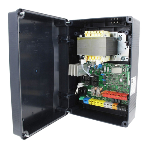
https://appceso.com
Table of contents
Languages:
Other BFT Control Panel manuals

BFT
BFT LEO-D-MA User manual

BFT
BFT LEO-D-MA User manual

BFT
BFT VISTA SEL User manual

BFT
BFT THALIA L Installation and operating instructions

BFT
BFT Q.BO PAD User manual

BFT
BFT NETTUNO B User manual

BFT
BFT PERSEO CBD 230.P SD User manual

BFT
BFT LEO B CBB DL2 3 230 L02 User manual

BFT
BFT ELBA User manual

BFT
BFT SHYRA AC SL User manual