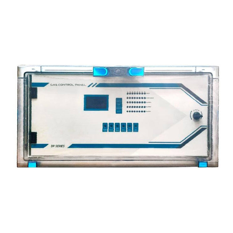
Prosense S-DP4 User manual

2
PRS-UM-DP4-EN-Rev.03-05.06.2020
WARNING!
READ THIS INSTRUCTION FIRST!
This manual must be carefully read by all persons who have or will have the
responsibility for installing, using or servicing this product.
Like any equipment, this product will perform as designed only if installed,
used and serviced in accordance with the manufacturer’s instructions.
Otherwise, it could fail to perform as designed and persons who rely on this
product for their safety could suffer severe personal injury or death.
The warranties made by Prosense with respect to this product are voided if
the product is not installed, used and serviced in accordance with the
instructions in this user guide. Please protect yourself and other by following
them.
WARNING!
Inductive or capacitive loads like motors, ventilation, e.g. should not be
directly connected to the panel directly. In such cases, auxiliary external
relays should be use to drive these loads.

3
PRS-UM-DP4-EN-Rev.03-05.06.2020
Contents
Introduction ........................................................................................................................................... 4
Technical Specifications .......................................................................................................................... 5
Panel Dimensions .................................................................................................................................... 6
Installation............................................................................................................................................... 6
Functions ................................................................................................................................................. 9
LCD Screen:........................................................................................................................................ 10
Special States..................................................................................................................................... 10
Fault Status:....................................................................................................................................... 10
Overrange Status Screen:.................................................................................................................. 11
Alarm Status: ..................................................................................................................................... 11
Main Board and Connections................................................................................................................ 12
Main Board Details: ........................................................................................................................... 12
Backup Battery Connection............................................................................................................... 13
Main Power Connection.................................................................................................................... 13
Detectors Connections ...................................................................................................................... 14
Relay Outputs .................................................................................................................................... 14
AUX Relay Output.............................................................................................................................. 15
First Run................................................................................................................................................. 15
Automatic Test .................................................................................................................................. 15
Programming......................................................................................................................................... 16
Single Channel Mode:........................................................................................................................ 16
Setup Channel Parameters:............................................................................................................... 17
Closing Unused Channels: ................................................................................................................. 19
Relay Assignment: ............................................................................................................................. 19
Time and Language Settings:............................................................................................................. 20
What to Do In Case of Alarm................................................................................................................. 21
Checking Alarm and Fault Functions ................................................................................................. 21
Controlling The Alarm Fault Functions.............................................................................................. 22
Prosense Panel Monitor Software Option ............................................................................................ 22
Declaration ............................................................................................................................................ 23
Warranty Statement.............................................................................................................................. 24

4
PRS-UM-DP4-EN-Rev.03-05.06.2020
Introduction
Prosense S-DP4 Control Panel is able to provide automatic gas concentration reading and
protection against gas explosions. S-DP4 permanently transmits the gas concentration
measurement from detectors to the control unit. Before the gas concentration in the
atmosphere reaches the L.E.L., the control panel is able to shut off a gas valve, cut off power
and turn on an alarm via activating relays when correctly integrated to related control
devices. Prosense S-DP4 Control panel can manage 4 analogue 4-20mA output gas detectors.
S-DP4 Control panel can manage explosive-flammable and toxic gas detectors as well as
oxygen detectors with direct connection to each detector via standard 4-20mA output.
Prosense S-DP4 Control panel has two levels of alarm which are adjustable according to the
measuring range and one fault alarm for the detection loop. Individual relays per function
ensure remote controlled output. There are 4 relays on the panel. Two of them used as
alarm relays and configured as ALARM-1 and ALARM-2. There is one FAULT relay and one
AUX relay. The AUX relay can be defined as ALARM-1, ALARM-2 or ALARM-3. ALARM-3 is not
a level based alarm but it is an alarm driven by digital input connected to another external
device.
S-DP4 has 128x64 LCD screen on the front panel to show status of each detector. This LCD
screen and menu keys allow user to set correct properties for each detector like gas
concentrations by gas type, measurement unit, and range and alarm levels.
S-DP4 Gas Control Panel complies to IEC 60079-0:2017 and IEC 60079-29-1:2016 standard
requirements. Please refer to the certification label on the control panel to identify the type
of certification that relates to the product supplied.
Diagram 1: Panel Label
The serial number of the product given with “DP4/???????” numbers.

5
PRS-UM-DP4-EN-Rev.03-05.06.2020
Technical Specifications
Power Source
220VAC ±10% 50/60 Hz
Power Consumption
27VDC/250mA - 6.75W max. (without connected detectors)
Inputs (Internal)
4 Analogue 4-20mA
Relay outputs
FAULT, ALARM1, ALARM2, AUX
Contact ratings
3A, 24VDC or 3A 120VAC
Display
Graphic LCD (128x64)
LED indicators
FAULT, ALARM1, ALARM2, AUX, BATT, POWER for overall status
Power/On, Fault, Alarm LEDs for each detector channel
Backup battery
12V 7A/h (Optional)
Operating Temp.
-10: +60C
0
Humidity
15-95% non condensing
Housing
ABS IP66 (546 X 276 X 186 mm)
Weight
5,75 kg
Main power fuse
2A
Backup battery fuse
2A
Warm-up time
Up to 2 minutes
Delay time
Panel can recognize any special state in 2 minutes
Special States
Fault (Fault Relay de-energised)
Overrange (Alarm Relay(s) energised)
EMC conformity
EN 61326-1 Group-1 Class-A
IEC conformity
IEC 60079-29-1:2106
Program release
V3.02
Special condition
Do NOT install in hazardous area
Table 1: Technical specifications

6
PRS-UM-DP4-EN-Rev.03-05.06.2020
Panel Dimensions
Panel dimensions are explained in Diagram 1:
Diagram 2: Dimensions (mm)
Installation
The S-DP4 control panel box should never be placed in an explosive atmosphere and should
be readily accessible. It is necessary to drill holes for cable glands either on the top or
bottom of the control unit, depending on which side the electric cables are running in.
Please unscrew and remove the electronic parts before drilling to avoid any accidentally
damaging. S-DP4 control panel should not be placed nearby high voltage cables or power
cable, coaxial cables or transmitters, welding stations or frequency regulators. The S-DP4
panel box produced based on IP66 standard specifications. Always use prepared screw holes
to mount it and do not pierce panel from any other side. Always use suitable cable glands to
make cable entries.
There is a front plastic cover to protect panel from outer shells, water and dust. To reach to
panel first you need to open plastic cover via pressing both sides of the latches on the front.
If panel ordered with keys a key needed to open plastic cover.
Press to open
Diagram 3: Front cover
Lock

7
PRS-UM-DP4-EN-Rev.03-05.06.2020
If panel ordered with keys a key needed to open plastic cover.
Diagram 4: Front cover with key
In order to make panel connection, you need to open the front cover using the key at right
bottom side of front panel. The key works clockwise and vice versa.
Diagram 5: Locker.
S-DP4 panel has 4 plastic screws keeping panel door in place in front of panel. Use a flat
screwdriver to lose them and remove the panel door assembly. Please take care and remove
the connectors on the electronic card while removing the cover. Fix the panel on to the wall
via using 4 screw holes in each corner after removing the front cover. M4 screws are suitable
to fix the panel body to the wall. Once wall mounting completed reattached the front cover
and tighten 6 plastic screws.
Diagram 6: Panel cover plastic screw
Plastic screws
Plastic screws

8
PRS-UM-DP4-EN-Rev.03-05.06.2020
To prepare cable entries, remove plastic cover from top or bottom on the panel. Then drill
the holes for cable entry and install cable glands to the holes you made it. Make sure you are
using an adequate IP66 rate cable gland to assure the box ingress protection is not
compromised. The panel box is modular and can be used with different assemblies. Prosense
recommends having cable entries from the lower side. Electronic board is located in the
front cover of the panel. The power supply is located at the back of panel box. The power
must be connected to this power supply. If the installation requires the connection to a
backup battery, place the battery to lover right side of the panel inside.
Diagram 7: Panel body
Backup battery connectors and fuse
Wall mounting hole
Power supply
N L G V-V+
Wall mounting hole
Wall mounting hole
Wall mounting hole
Main power entry and fuse
Space for backup
batteries
Power supply LED
Power supply output
adjustment switch

9
PRS-UM-DP4-EN-Rev.03-05.06.2020
Functions
The front panel has the following indicators as shown in Diagram 4:
Sign
Meaning
BATT
Main Power lost, Battery in operation
AUX
AUX ( assigned as ALARM1, ALARM2 or ALARM3*)
AL1
ALARM1
AL2
ALARM2
FAULT
Fault condition in at least one of the detector
POWER
220 VAC Operate
ON
Operation LED for each detector (8 green LEDs)
FAULT
Fault LED for each detector (8 yellow LEDs)
ALARM
ALARM LED for each detector (8 red LEDs)
Table 2: Front panel signs and meanings
There are four buttons nearby LCD screen to perform configuration and display the detector
details. Their functions are given in table (The key assignments may vary depending on the
menu page):
Key
Function For Configuration
Function For Display Operation
MENU
Enter to panel configuration
OK - Select key
UP
Go to upper menu option during configuration
Go to the single channel details in normal operation
DOWN
Go to lower menu option during configuration
Page change on main screen
EXIT
Undo or exit from menu option
Reset on main screen
Table 3: Panel buttons and functions
Diagram 8: Front panel signs LCD and LEDs
S-DP4 Panel has LEDs formed in 8 columns and three rows. LEDs are grouped per channels
and each channel has ON, FAULT and ALARM LEDs to show actual status of the detector. C1,
C2, C3,C4 numbers used to identify channels and each column indicate the detector
information as follows:
ON : Indicates detector on related channel is working and communicating to system
FAULT : Indicates detector on related channel is in fault condition or not communicating
ALARM: Indicate detector on related channel has reached specified threshold level

10
PRS-UM-DP4-EN-Rev.03-05.06.2020
LCD Screen:
LCD screen shows time details and status of each detector connected to channels as shown
in Diagram 8:
Diagram 9: LCD screen
Note: Date and time information will be unavailable when RS485 module installed.
The meaning of the signs used in LCD screen is given in table 4:
Column
Sign sample
Meaning
1
1>
Channel number
2
DETECTR
Detector name (user can give any name)
3
17
Gas level measured by detector
4
LEL
(LEL, VOL, PPM) measurement unit of detector
5
A1
ALARM1 is active
5
A2
ALARM2 is active
5
FLT
FAULT status
Table 4: LCD screen details
If there is no detector connected to channel, LCD screen will show it as FLT and fault LED will
be activated. That channel should be closed (deactivated) via using menu steps.
The LCD screen brilliance is adjustable by blue potentiometer shown in Diagram 9.
Special States
Panel can recognize any special state in 2 minutes. Special States are:
•Fault
•Overrange
Below messages wil be shown on LCD and related visible alerts will be activated:
Status
Screen Output
LED Output
Relay Output
Fault
Fault status on related channel
Fault LED
Fault Relay de-energised
Overrange
“Range<” message shown on related channel
ALARM LEDs
Alarm Relay(s) energised
Table 5: Special state and indicators
Fault Status:
The panel reports FAULT status in below cases:
•In case any of the detector connections lost
•In case any of the detector measurement level goes below minimum level
•In case any of the detector goes in to fault state
•In case any panel self-test result reports a fault

11
PRS-UM-DP4-EN-Rev.03-05.06.2020
•In case panel main power lost and while panel is working with battery power
•In case panel main power supply fails
This status has been detected by panel when an input signal is below 3mA and reported on
LCD screen on related channel with “FLT” symbol. Panel will activate FAULT relay and LED in
case of any fault. Panel also activate fault LED for related channel if the fault status detected
on a detector channel.
Fault relay is normally energised, and it will be de-energised when any of the internal fault
detection measures detects a fault. The Fault LED will be activated also when line power is
lost and system runs with battery power. It is also possible to get an alarm when control
panel totally loses the power.
Overrange Status Screen:
The panel also report overrange status in case any of the channels reported measurement
higher than measurement range. This status has been detected by panel when an input
signal is over range (> 20mA) and reported on LCD screen on related channel with “Range<”
symbol and measurement level fixed to 99LEL. The overrange condition is highes
measurement level that panel can understand and overrange level is higher than alarm
levels. The alarm LEDs and relays will be activated before panel reports overrange condition.
Diagram 10: Overrange status display
Alarm Status:
The Panel will report Alarm status when gas level exceedes defined alarm levels on any of
the detector channel. Panel has two adjustable measurement alarm levels. If any connected
detector measurement reaches the given alarm threshold level, panel will activate related
alarm relay and LED. Alarm-1 relay and LED will be activated in case any of the connected
detector measurement reaches defined Alarm-1 threshold level. Panel will show "AL1"
symbols for the related channel on LCD screen and also activate alarm LED on related
channel. Alarm-2 relay and LED will be activated in case any of the connected detector
measurement reaches defined Alarm-2 threshold level. Panel will show "AL2" symbol for the
related channel on LCD screen and also activate alarm LED on related channel. Alarm-1 and
Alarm-2 relays and LEDs will be both active in case any of the connected detector reports
Alarm-2 status.

12
PRS-UM-DP4-EN-Rev.03-05.06.2020
Main Board and Connections
S-DP4 Control panel has one integrated main board. All componenets and connections are
located on main board.
Main Board Details:
S-DP4 Control panel has all connections on main board.
Diagram 11: Control panel main board
As shown in the picture, there is a 3V battery on the panel electronic board to keep data and
time information. It may operate during the normal lifetime of the control panel. It should
be replaced when it is run off.
There are five sockets on the main board to install optional relay modules. Each relay
module has 8 relay on it and each relay controlled by one detector. It is also possible to take
an independent output from each relay (each detector). The relay module install location
should be used as follows:
1. Zone (1. Bölge): Not in use
2. Zone (2. Bölge): Fault
3. Zone (3. Bölge): Alarm 1
4. Zone (1. Bölge): Alarm 2
5. Zone (1. Bölge): Not in use
LCD brightness adjustment potentiometer
Relay module mounting holes
Main power
input
Backup
battery input
Detector input ports
Clock battery
Digital input
Relays and relay outputs
Buzzer
Relay test buttons

13
PRS-UM-DP4-EN-Rev.03-05.06.2020
There are 4 cube relays on main board and relay outputs can be taken from the terminals on
the bottom of relays. The relays are used for Fault, Alarm 1, Alarm 2 and Aux outputs. There
are test buttons at the top of each relay that can help to generate artificial alarms for testing
purposes.
S-DP4 Panel has a buzzer on the main board to generate sound alarms. A digital input port
provided on main board that should be 24VDC. To activate this input the AUX relay must be
defined as Alarm-3 to work with digital input. Otherwise it does not provide any output.
The detector connections are located on left bottom side of the controller panel board.
Not: The electronic board may become hot when the panel is in alarm status for a long time.
Backup Battery Connection
To continue operation in case of main power failure two backup batteries (12V 7Ah) must be
serially connected to the system. Take extra care to connect the batteries with correct poles.
The cables or main board can be damaged in case of mixing pins or making short circuits.
Backup batteries must be connected as shown below.
Diagram 12: Backup battery connection
Main Power Connection
Connection must be made three-wire 1.5mm2cross section cable to the main supply
terminal entries and fixed by using cable fastener on the terminal. Make sure all the
detectors connected properly before applying the power.
Name
Type
Usage
L
input
Phase
Gnd
input
Ground
N
input
Neutral
V+
output
+24VDC (Only for panel and detectors, do not use for any other device)
V-
output
-VDC
Table 6: Main power connection details
Panel battery input
V+
V-
V+
V-
Battery 1/ 12V 7Ah
Battery 2/ 12V 7Ah
V-
V+

14
PRS-UM-DP4-EN-Rev.03-05.06.2020
Detectors Connections
Panel can be connected and monitor 8 detectors with standard 4-20mA inputs signal. V+, V-
(GND) and S ports must be connected via using three-wire cable. Detector connections
supply 24VDC power to detector and read the output signal of detector from S port. Thus
connections should be made correctly to do not cause any damage on the detectors.
Detectors should be connected with three-wire 0.5mm2cross section cable. Cable diameter
will be increased while distance increase between the panel and detectors. Recommended
cable types per distance are given in table 6:
Cable size
Cable type
Cable resistance
Maximum Cable length (L)
(cross sectional area)
nearest equivalent
Ω/km
Meters
0.5mm2
20AWG
36.8 Ω/km
400
1.0mm2
17AWG
19.5 Ω/km
750
1.5mm2
16AWG
12.7 Ω/km
1000
2.0mm2
14AWG
10.1 Ω/km
1250
2.5mm2
13AWG
8.0 Ω/km
1500
Table 7: Typical cable details and maximum distance for cabling
Detector connections should be made with 3 core cable and pin definitions are as follows:
S
4-20mA signal
-
GND (V-)
+
Supply (V+)
Table 8: Connection pin definitions
The panel is programmed as all channels in operation and connected to detectors. In case
less than 8 detectors used the system will raise fault status for unused channels and overall
panel status remain in fault status. In this case user should close (deactivate) unused
channels via using configuration menu steps.
Relay Outputs
S-DP4 panel has four relay outputs which are ALARM1, ALARM2, FAULT and AUX. Relay
connection ports are located right under the relays. Alarm relays are operating in latched
mode. Hence the panel will wait user intervention to clear alarm status even conditions
returned to normal. User should reset status via pressing Exit button to acknowledge any
alarm. The active relays can also be monitored via related LEDs on the panel. Relay details
and activation rules are given below:
ALARM1: This relay will be activated when any of the detectors in the system will exceed the
programmed Alarm-1 level threshold. If there is oxygen detector used in the system,
ALARM1 is also used as the low oxygen level alarm.
ALARM2: This relay will be activated when any of the detectors in the system will exceed the
programmed Alarm-2 threshold level. If there is oxygen detector used in the system,
ALARM2 is also used as the high oxygen level alarm.
FAULT: This relay will be activated when any of the detectors in fault status or any panel self
test function fails. The Fault LED will be activated when line power lost and system runs with

15
PRS-UM-DP4-EN-Rev.03-05.06.2020
battery power. The Fault relay is energised and it is possible to get an alarm when control
panel totally lost the power
If needed user can obtain independent alarm and fault outputs from each detector via using
optional relay module. Relay modules should be installed reserved zone sockets explained
earlier. The relays are configured as NO (normally open) by default at factory. The relay
configurations can be adjusted via putting jumpers under each relay. Relay will not provide
output while jumpers are omitted or not installed. Relay connections pins are:
NC : Normally closed contact pin (Select by jumper under relay)
NO : Normally open pin (Select by jumper under relay)
COM : Common pin
Note: Relays should not be connected to high current or 220V AC loads. The relay outputs
should be used as control signal and external relays should be used to drive such devices as
relay on main board cannot handle high load.
AUX Relay Output
Aux relay can be programmed from the main menu on the panel to match to ALARM1,
ALARM2 or ALARM3. When ALARM1 is selected, AUX relay will operate simultaneously with
ALARM1 relay of the system. When ALARM2 is selected, AUX relay will be active when
ALARM2 relay activated. When ALARM3 is selected, AUX relay will be active by the digital
input on the panel. In case of any alarm signal received from external device it will be shown
in 5th line on LCD as digital alarm.
First Run
Panel manufacturer (Prosense) and model (S-DP4) will be seen on LCD screen following the
power-up. All LEDs on the panel and sounder device will be activated for 3 seconds. The user
can recognize any malfunctioning LED on panel at this period. The Fault relay and LED will be
activated during the warm-up period. The panel will start searching channels one by one and
activate the channel power and fault LEDs. This operation may take two minutes. During this
period, system will operate in standby mode until the detectors are warmed up.
Instantaneous alarms will be turned off during the warm-up period.
Panel will activate status LEDs per channel depending of the detectors connected to each
channel following search and warm-up time. Also status will be shown on LCD screen. If all of
the detectors run smoothly, the Fault LED will turn off.
Automatic Test
S-DP4 gas control panel simultaneously monitor all detectors connected to it. Panel should
have power LED and connected detector Channel ON LEDs during normal operation. S-DP4
panel also runs internal component tests at the warm-up time and every 8 hours. The FAULT
relay and LED will be activated in case any problem. Alarm and fault status can be monitored
on the screen and via checking related detector LEDs.

16
PRS-UM-DP4-EN-Rev.03-05.06.2020
Programming
The panel is already programmed and ready for using when shipped. User should adjust the
alarm settings via changing alarm levels for each channel depending on the detectors
installed. Each channel parameters should be adjusted regarding related detector
measurement unit and range. These adjustments can be done via using the keys nearby LCD.
Each detector can also be named in the menu. The menu steps are given in Diagram 11.
Diagram 13: Menu structure
S-DP4 control panel keeps data and time information to record alarm events in the internal
log space. The alarm logs menu is not available when panel uses RS485 module to
communicate to Prosense Panel Monitor software.
To activate configuration menu, press and hold the MENU button for a second. You can
navigate between the menu items via using the UP and DOWN keys. Press MENU key again
to enter submenu. You can EXIT from submenu or menu by pressing the EXIT button.
1. Channel setting
2. Time / Language settings
3. Relay assignment
4. Alarm logs
Single Channel Mode:
To see each detector status in detail, press UP button on the main menu. Screen will switch
in to single channel mode. Then it will display detector status, instant reading value, alarm
status and detector name:
If there is any fault or alarm it will be displayed right bottom corner of screen:
1- Channel setting
2- Time/Language settings
3- Relay assignment
4- Alarm logs
1. Detectr.
2. Detectr.
3. Detectr.
4. Detectr.
MENU
1-Detector Setting
Aux > Alarm2
Alarm > automatic
hour. min. sec day/
month/ year
4-Alarm logs
2-Time Setting
3-Relay Assign
1>D4 F3 23/06 15:55
2>D3 A1 23/06 12:12
Main menu screen

17
PRS-UM-DP4-EN-Rev.03-05.06.2020
You can switch between channels via using UP or DOWN buttons. Also you can directly reach
alarm logs screen via pressing MENU button in single channel mode. Logs keep alarm and
fault details with their date and time for last 24 hours. You might use UP and DOWN buttons
to see all records. Press EXIT button to return main menu. Screen will automatically exit from
the single channel menu to main menu after 2 minutes if there is no user action.
Setup Channel Parameters:
To adjust channel parameter follow below steps.
1- Press Menu button for 2 seconds. The screen will display menu options:
2- Select Channel setting via pressing the MENU button. Screen will list channels:
3- Move desired Channel from the list via using UP and DOWN buttons and press MENU
button to select channel. A new menu will display with below options:
4- To adjust measurement range select "Range Assign" option. Screen will display default
measurement settings:

18
PRS-UM-DP4-EN-Rev.03-05.06.2020
You can change measurement type via pressing up and down buttons to select LEL, VOL, and
PPM. Once selected press MENU button. Then screen will display Range options:
You can select below values for range
for LEL: 0-50 or 0-100
for VOL: 0-5 or 0-25 or 0-30
for PPM: 0-10 or 0-20 or 0-30 or 0-100 or 0-200 or 0-250 or 0-300 or 0-400 or 0-500 or 0-
1000 or 0-5000
Once selected press EXIT button to return Channel Settings menu.
5- To adjust alarm levels first you have to complete measurement range settings. Then move
"Alarm levels" option on channel setting screen and select via pressing MENU button. Screen
will display default alarm level settings:
6- When press MENU button a cursor will be located under Alarm1 level. You can adjust
alarm level via using UP and DOWN buttons.
7- Then press EXIT button to release the cursor.
8- Then you can move Alarm2 via using UP or DOWN buttons.
9- Press MENU button again to activate cursor and adjust level using UP and DOWN buttons.
10- Once all completed press exit button to return the previous screen.
Alarm1 level cannot be higher than Alarm2 level. Hence it would be easier to adjust Alarm2
level first before adjusting Alarm1 level.
11- You can give a name to channel instead of default “Detectr”. Move “Define Name”
option on Channel Settings screen via UP and DOWN buttons and select via pressing MENU
button. The screen will show default name and cursor:
You can change each letter via using UP and DOWN buttons. Press MENU button to record
and move to the next letter.
12- Once all completed press EXIT button to return main menu.

19
PRS-UM-DP4-EN-Rev.03-05.06.2020
Closing Unused Channels:
Unused channels should be deactivated if not all channels used on control panel. Otherwise
unused channels and control panel will stay in fault status. To deactivate unused channel go
to the Channel Settings menu via pressing the MENU button. Then move related channel via
using UP and DOWN buttons and select channel with MENU button. You will see the below
detailed settings menu:
The fourth step on this menu pointing the actual status of the channel. “Open” means
channel is active. To close this channel move to the option 4 on screen via UP and DOWN
buttons then press MENU button to change status. It will be deactivated and shown like
below:
Relay Assignment:
The alarm relays work only in latched mode. Therefore, the relay will not be released and
stay in active mode till manual intervention. Even after environment is cleaned following an
alarm condition, the relay will stay active in latching mode. User should release them via
pressing the EXIT button for 2 seconds. Pressing the EXIT button will reset and stop alarms
temporarily. The control panel will perform measurement again when user released the EXIT
button. If gas measurement is still higher than given threshold levels alarms will be activated
again.
To change relay assignment press MENU button on main screen and select “Relay Assign”
option. The screen will display default working mode for all relays and assignment for AUX
relay:

20
PRS-UM-DP4-EN-Rev.03-05.06.2020
Press MENU button to change AUX relay assignment. A cursor will be activated on the screen
and you can change assignment via using UP and DOWN buttons. Press EXIT button to save
assignment and return the screen. When AUX relay assigned to ALARM3, Digital Input port
will be activated on the panel. In this case it will be shown as 9th line on LCD as “Digital
Alarm” in case an alarm status received from external device:
Time and Language Settings:
Press MENU button and select “Time/Lang. Set” step to change time and date. If
communication module installed on the menu will show only Language options. A new menu
will be displayed including time and language options:
Press MENU button to adjust time. Screen will show current time and date information on
the control panel.
Use UP, DOWN and MENU buttons to change value and move to the next item on the
screen. Once completed press EXIT button to return to settings screen.
You can change the screen language on Language menu. Only Turkish and English languages
available at the time of writing this manual:
Table of contents
Other Prosense Control Panel manuals
Popular Control Panel manuals by other brands

SJE Rhombus
SJE Rhombus 112 Installation Instructions and Operation
vds
vds EURO 230 M1 ECO manual
Panasonic
Panasonic AG-RCP30P operating instructions

Ariston
Ariston Chaffoteaux 3301556 installation instructions
Eaton
Eaton DF6100 Installation and operation manual
Menvier
Menvier Zone Omit 5158 2 Series installation guide
GRASS VALLEY
GRASS VALLEY OCP 400 user guide
Tyco
Tyco RAPID RESPONSE RCP-1 manual
Rosslare
Rosslare AC-425IP-BU Hardware installation and user's guide
Topcon Positioning Group
Topcon Positioning Group RDS TECHNOLOGY ISOCAN APOLLO FYM quick start guide
Ricoh
Ricoh Smart Operation Panel manual
Bandini Industrie
Bandini Industrie GiBiDi PLUS1B Instructions for installation

