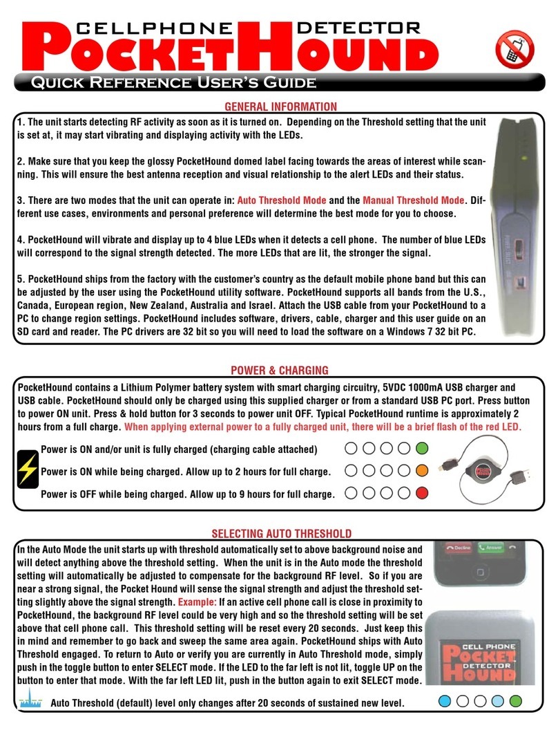
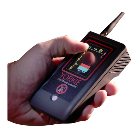
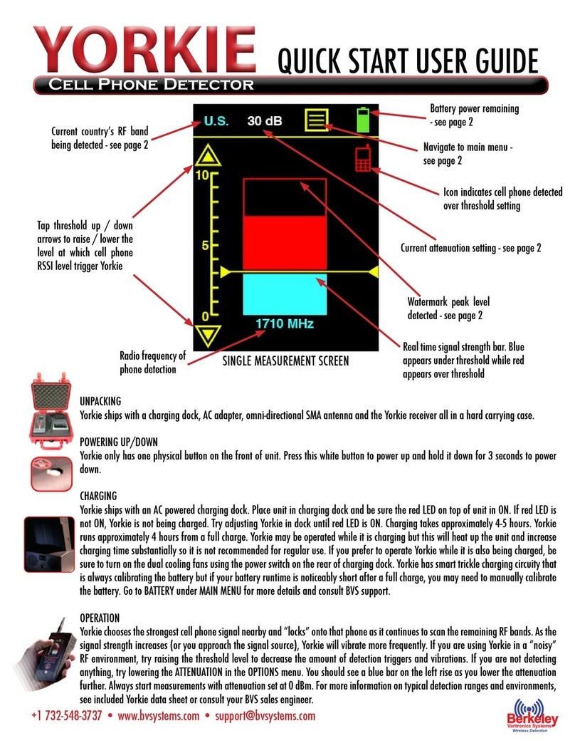
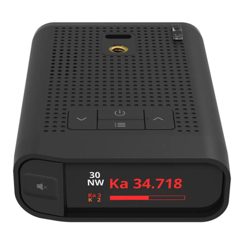
Berkeley Varitronics Systems wolfhound pro User manual

User’smanualversion1.6

2
TableofContents
Contents.........................................................................................................................................2
INTRODUCTION..............................................................................................................................4
ItemsSupplied.........................................................................................................................................5
Wolfhound-PROUNITDESCRIPTION..............................................................................................7
OrganicLightEmittingDiode(OLED).......................................................................................................9
Higher-LevelMenuScreens...................................................................................................................10
MAINMENUScreen(highest-levelmenu).........................................................................................10
MEASUREMENTSScreen...................................................................................................................11
PhoneDetectionMode......................................................................................................................11
DirectionFindingMode.....................................................................................................................14
FrequencyDiscriminatorMode.........................................................................................................15
DirectionFindingScale......................................................................................................................16
ThresholdMarkerSetting..................................................................................................................16
ResetMaxBars..................................................................................................................................17
DECT6.0DetectionMode..................................................................................................................17
SETUP...........................................................................................................................................18
AntennaConnection..............................................................................................................................19
AttachmentofOmnidirectionalAntenna..........................................................................................19
AttachmentofDirectionFinding(DF)Antenna.................................................................................19
ActivatingAccessories(Sound/Vibrater/Laser)....................................................................................20
AdjustingVolume..............................................................................................................................21
SelectingFrequencyBand..................................................................................................................22
AddingAttenuation(ifnecessary).....................................................................................................23

3
InformationScreen................................................................................................................................23
LoadingDefaultParameters..................................................................................................................24
OPERATION&USE........................................................................................................................25
ResettingtheMaximum-HoldMarker...................................................................................................25
Antennas................................................................................................................................................25
GeneralGuidelinesforGoodSignalReception......................................................................................26
MonitoringCellPhoneUseinReal-Time...........................................................................................26
MonitoringCoarseScaleMaximumHold..........................................................................................26
UsingWolfhound-PROUnitwiththeOmnidirectionalAntenna...........................................................26
UsingtheWolfhound-PROUnitwiththeDirectionFinding(DF)Antenna…………………………………….……26
Method1:MaximizingSignalAlongtheSameLOP..........................................................................28
Method2:“Triangulate”withTwo(ormore)LOPs...........................................................................29
MAINTENANCEandTROUBLESHOOTING.....................................................................................30
ChargingBatteries.....................................................................................................................................30
Appendix1:SynopsisfortheoptionalWolfhound-PROPCSoftware………………………………………..……………31
Wolfhound-PROWindowsSoftware…………………………………………………………………………………………………….32
Introduction…………………………………….…………………………………….………………………….…………………………………32
InstallationofSoftware………….…………………………………….…………………………………….………………………………32
GettingStarted…………………………………………………….…………………………………….…………………………………….…32
Realtime………….…………………………………….…………………………………….…………………………………….…………………34
Statistics……………………………………………….…………………………………….…………………………………….…………………35
Settings……………..…………………………………….…………………………………….…………………………………….………………36
Help………………….…………………………………….…………………………………….…………………………………….………………39

4
INTRODUCTION
The Wolfhound-PRO cell detector uses a narrow-band/high-selectivity receiver controlled by an on-board
processor. The Wolfhound-PRO receiver has a resolution bandwidth of 4 MHz and uses a square-law
detector. The receiver can be set to scan multiple up-link frequency bands assigned to North America, the
European Union, Asia and Australia, as listed in Table 1:
AAiirrIInntteerrffaaccee
T
T
e
e
c
c
h
h
n
n
o
o
l
l
o
o
g
g
y
y
UUpp--LLiinnkkFFrreeqquueennccyy
B
B
a
a
n
n
d
d
(
(
M
M
H
H
z
z
)
)
North America
LTE Uplink
698 – 716 MHz
777 – 787 MHz
788 – 798 MHz
GSM-850, GSM-900, CDMA, Cellular
824 – 849 MHz
896 – 901 MHz
AWS Uplink
1710 – 1755 MHz
PCS
1850 - 1910 MHz
DECT 6.0
1920 – 1930 MHz
GPS Tracking Devices (GSM)
850/900/1800/1900 MHz
Europe/Asia/Korea/Australia/Brazil/New
Zealand/Israel/Canada/Japan
EGSM-900
Europe, Asia, Australia, New Zealand
880 – 915 MHz
GSM 1800 (DCS-1800)
Europe, Asia, Japan
1710.2 - 1784.8 MHz
WCDMA/UMTS
Europe, Asia, Korea, Japan, Australia,
Brazil, New Zealand
1920 – 1980 MHz

5
The receiver detector output is used to drive one or more of the following indicators:
1. height of coarse and fine bar charts in the OLED display
2. pulsing rate of Laser (optional accessory mounted on DF antenna assembly)
3. pulsing rate of Sound Alert (speaker or ear bud)
4. turning on Vibrator Alert (fixed rate)
The Wolfhound-PRO unit is normally used in the hand-held mode either with an Omnidirectional
antenna for cell phone detection only (see left side of Figure 1 below), or with a Direction Finding (DF)
antenna for identifying the relative orientation (i.e. Line Of Position) of a radiating cell phone. Either
antenna is connected to the Wolfhound-PRO unit RF coaxial port located at the OLED end of the unit as it
can be observed from the two photos in Figure 1.
Figure1.Wolfhound-PROUnitmaybeusedwiththeOmnidirectionalorDirectionFinding(DF)Antenna

6
ItemsSupplied
The standard package (as shipped) includes the Wolfhound-PRO unit and accessories, including a
carryingcaseasseeninFigure2:
Wolfhound-PROCellDetectorunit
Operatorsmanual
VELCROhandstrap
Earbud
ExternalACPowerCharger
Omnidirectionalmonopoleantenna
DirectionFinding(DF)Antennaassembly
MiniUSBcable
Pelican®briefcase(blackwithsecurelockandkeys)
Figure2.Wolfhound-PROunitandaccessories
Optionally,thefollowingitemsarealsoavailable:
GreenLasermodule(mountedonDFantennaassembly)
PCSoftwarepackage(forreal-timemonitoring,dataloggingandreportgeneration)1
1SeeAppendix1belowforasynopsisofthefunctionsperformedbythissoftware.

7
Wolfhound-PROUNITDESCRIPTION
Wolfhound-PRO(trackball model) unitappearin Figure 3. The unit has an OLED, navigation trackball,
fiveelectricalinterfacesandanLEDaslistedbelow(seealsoarrows1,2,3,6,7and8inFigure3):
1. Antennaport
2. Audio(earbud)jack
3. DCPowerjack
4. LiquidCrystalDisplay(OLED)
5. Trackball(rollfor2Dcursornavigation/pressdownforselecting)
6. Laserjack
7. MiniUSBjack
8. BatterystatusLED(Red)
Figure3a.TheWolfhound-PROUnit,Controls,IndicatorsandInterfaces

8
Note:SomeWolfhound-Promodelsutilizeasingletrackballformenunavigationandcontrolwhileother
Wolfhound-Promodelsusea5-buttonlayoutfornavigation.Bothunitsareidenticalinperformanceandfeatures
leavingtheappearanceandphysicalnavigationastheonlydifferencebetweenthetwomodels.
1. Navigate/adjustupmenu
2. Navigate/adjusttotheright
3. Navigate/adjustdownmenu
4. Navigate/adjusttotheleft
5.Selectordeselecthighlightedicon/PowerONunit
Figure4b.TheWolfhound-PROKeypadPushbuttonNavigationControls

9
OrganicLightEmittingDiode(OLED)
TheWolfhound-PROunitcanbe turnedonby holdingdownthe trackballorblackcenterpushbutton
(seearrow5inFigure3)atleastforaboutasecond.Whentheunitispowered,theambermonochrome
OLEDwilldisplayoneof thethreemeasurementscreens(Phone Detection,DirectionFindingorDECT
6.0 Detection) from which the unit was turned off. Thus, if the unit was being used in the Direction
Findingmodejustbeforepoweringoff,nexttimeitispoweredontheOLEDwilldisplaytheDirection
FindingscreeninFigure4:
Figure4.OLEDdisplayingtheDirectionFindingScreen
Theunitcanbepoweredoffonlyfromoneofthethreemeasurementscreens,bychoosingthepower
icon in Figure 4 (the power icon is nearest to the lower right-hand-corner of all three measurement
screens).
Higher-LevelMenuScreens
MAINMENUScreen(highest-levelmenu)
TheWolfhound-PROunitMAINMENUscreen(seeFigure5)isaccessedbyselectingtheinformationicon
“i”fromanyoneofthethreemeasurementscreens(seeFigure4).
Figure5.MAINMENUScreen

10
Clicking“Back”inFigure5orinanyotherscreenwhere“Back”appearswilltaketheusertothenext
higher level menu or screen. The first four items in the MAIN MENU (i.e., Measurements, Effect
Options,SettingsandInformation)arediscussednext:
MEASUREMENTSScreen
Clickingon“Measurements”fromtheMAINMENU(Figure5)willyieldtheMEASUREMENTSMenu:
Figure6.MEASUREMENTSMenuScreen
Thismenuallowstheusertoenteroneofthethreemodesofreal-timemonitoringoftheWolfhound-
PROunit:
PhoneDetectionMode
Inthismode (seeFigure7),theWolfhound-PROwilldetecttheuseof oneormorecellphoneswhile
monitoring the relative strength of the source signal(s) and frequencies using the Omnidirectional
antenna. The frequency band needs to be selectedvia the BAND SELECTION screen. The frequency
indicationcorrespondstothestrongestsignaldetectedintheselectedfrequencyband,usingacoarse
bar-chartvaryinginheightonarelativescaleof0to10.Eachdivisiononthecoarsescalecorrespondsto
approximately6.4dBchangeinsignallevel.Inthismodecellphoneusecanbedetectedbutdirectionof
maximumsignalstrengthcannotbedetermined.
Figure7.PhoneDetectionMode

11
1
TypicalScreen
Figure8.TypicalScreenIcons
ThescreenandiconsshownisthetypicalDirectionFindingscreenbutsharesmanyfunctionsandicons
ofmostothermeasurementscreensintheWolfhound-PRO.
1CoarseBarChart:Indicatesinstantaneoussignalstrengthonascaleof0to10.Maximumhold
indicationprovidedbythetwodashesateachsideofbar-chart.
2ThresholdSettingmarker:Thresholdsettingisadjustedbypressingtheballdownonthe“T”
iconontheright(seeFigure13),thenrollingtheball(upordown)tothedesiredlevelwith
respecttothebarchartscaletotheleft,thenclickingtheballdown tolockmarkersetting.
ThissettingcontrolsboththeFrequencyFieldandCellPhoneiconindicators(arrows4and5).
3Direction Finding Features Toggle: This icon will only displaywhen in the Direction Finding
selection in the Measurements menu. Selecting this icon and toggle through the following
modes:Threshold(T),ResetMaximumHold(arrowpointingdown),FrequencyDiscriminator
Mode(singlecellphone),ScanAllMode(3cellphones),DirectionFindingMode(scale).Once
4
6
7
3
8
9
13
11
10
5
2
12

12
you see the function you like, selectthat icon and push in the black center pushbutton or
trackball(modeldependent)toselectthatfunction.
4Direction Finding Scale: This vertical scale only appears when Wolfhound-PRO is in the
DirectionFindingmode.Thisscalemeasuressignalstrengthlikethescaletotheleftofitbutat
afinerresolutionmakingitusefulforsensitivedirectionfinding.
5CellPhoneicon:Thisfixediconturnsonwhenanysignallevelinthefrequencybandexceeds
thethresholdmarkersetting.
6GeographicRegion:Thisfieldindicatesoneofmultiplepossiblefrequencybandsettings.
7InformationIcon:SelectingthisiconbringsbacktheMAINMENUscreen
8Direction Finding Mode: Selecting this icon puts the Wolfhound-PRO into Direction Finding
Mode.ThemoregranularRSSIscaleontherightwillappearinthismode.
9Power Off Icon: The unit is turned off by selecting and pressing the ball down on this icon
fromanyoneofthethreemeasurementscreens(i.e.,PhoneDetection,DirectionFindingor
DECT6.0Detection).
10 BatteryStatusIcon:ThisiconindicatesthechargestatusoftheinternalLithiumIonPolymer
battery.Startingwithanalmostemptybattery,astheunitischargedbytheACcharger,this
iconwillchangefromanemptyrectangletoa solidamberrectangle.Ifusedover5.5hours
without charging, the unit will eventually turn itself off to avoid permanent damage to the
battery.Aslongasthebatteryischarging,thebatterystatusLED(red,seearrow10inFigure
above)willbeON.
11 LaserPulse Indicator: This icon shows that the pulsing laser is active and should be visible
whileacellphoneisdetected.Note:itmaybedifficulttoseethegreenlaserpulseinbright
conditions.Trypointingdeviceataclosewallorcornertoseelaser.NEVERlookdirectlyinto
laserforanyreason.
12 VibratorIcon:Thisiconshowsthatthevibratingalertmodeisactivesoyoushouldfeelthe
Wolfhound-PROunitvibratingduringcellphonedetection.
13 Audible Alert Icon:This icon shows that the audible alertis active so you should hear the
Wolfhound-PROunitbeepingduringcellphonedetection.

13
DirectionFindingIcons
Theseareiconsappearinthedirectionfindingmodeandtheirfunctionsareallusefulwhenperforming
directionfinding:
SelectthisicontotogglethroughthefollowingfunctionsintheDirectionFindingMenu:
SelectthisicontosetThreshold.The iconwillchangeto foradjustment.Lower
orraisetheThreshold.Pushthetrackballorblackcenterpushbuttontoselectnewlevel.
Selectthisicontoresetmaximumsignaldetectedbar.
Selectthisicontoremovethestrongestsignalfromthelistofdetectedphones.
Selectthisiconto“see”allcellphonesdetected.
SelectthisicontoentertheDirectionFindingmeasurementmode.

14
DirectionFindingModes
ThismodeofmeasurementallowstheusertodeterminetheLineofPositionofaradiatingcellphone
(or,thedirectionfromwhichthecellphoneisradiating),aswellasdetectingthecellphonesignal(see
Figure9).Thefrequencybandneedstobeselected(US,EU,AU,....)viatheBANDSELECTIONscreen.
Figure9.TheDirectionFindingModes
WithintheDirectionFindingmodetherearetwodifferentfeaturesthatallowtheusertodetectcell
phoneswithgreateraccuracy.Thesefeaturescanbefoundbyhighlightingthespinningwheeliconand
selectingit.
HerearethetwodifferentfeaturesintheDirectionFindingmodefollowedbyabriefdescriptionfor
eachone:

15
FrequencyDiscriminatorMode:
Figure9.FrequencyDiscriminatorMode
TheFrequencyDiscriminatormodeallowstheusertoremovethestrongestsignalofacellphonefroma
particularfrequencyband.Thisapplicationishelpfulwhenaknowncellphoneisdetectedandneedsto
befilteredoutbytheWolfhoundPROsotheusercanfindotherhiddencellphonesinthesame
frequencyband.Whenthismodeisactivatedthebandselectionwilldisplay“-“wherethefrequency
justappeared.
TodeactivatetheFrequencyDiscriminatormodehighlighttheiconshowninfigure11andselectit.The
iconshowninfigure12willappearandthebandselectionwillbedisplayed.
FrequencyDiscriminatorMode:
Figure11.FrequencyDiscriminatorMode

16
DirectionFindingScale:
Figure12.DirectionFindingScale
WhentheDirectionFindingmodeisactivated,agraphappearsallowingtheusertoseegreater
granularityofthedetectedcellphonesignal.ItisrecommendedtousethismodewiththeDirection
FindingantennaattachedtotheWolfhoundPROtouncoverhiddencellphones.Asthesignalincreases
ordecreasesinthegraphtotherighttheusercandeterminethedirectionofthecellphone.Formore
detailsonsettinguptheDirectionFindingAntennarefertoAttachmentofDirectionFindingAntenna.
ThereisalsotheThresholdMarkerandtheResetMaxBarsiconsthatarefoundusingthespinning
wheelicon.
ThresholdMarkerSetting:
Figure13.ThresholdMarker

17
TheThresholdMarkerSettingallowstheusertosetalineanywherealongthescaleontheleft.Should
theWolfhound-PROdetectasignalthatexceedsthatthreshold,theuserwillbealertedwithoneor
morealerts(seeActivatingAccessoriesforinformationonthis).Tochangethethresholdmarker,
highlighttheTiconandselectit.TheTiconlocatednearthescalecannowbemodifiedupordown
usingthetrackballorup/downbuttonsonthekeypad(modeldependent).Pressthetrackballorkeypad
centerpushbuttonagaintosetthedesiredlevel.
ResetMaxBars:
Figure14.ResetMaxBars
TheResetMaxBarsmodeisactivatedwhentheuserhighlightsthespinningwheeliconandselectsuntil
thedownarrowiconappearsasshowninFigure14.Onceacellphoneisdetectedandthebarappears,
themarkerswillmovetothemaximumleveldetectedandremainthere.Thismodeishelpfulwhenthe
userisbusywhilecellphoneactivityisoccurring.Tosetthemarkerstozero,selectthedownarrow
iconwhileitishighlighted.

18
DECT6.0DetectionMode
DECT 6.0 cordless phone monitoring is initiated from the MEASUREMENTS screen, regardless of
frequencybandselection.ThevariousfieldsintheDECT6.0Detectionscreenareidenticaltothoseof
theDirectionFindingscreenwiththeexceptionoftheGeographicRegionfieldasfollows(Figure7):
Figure15.DECT6.0DetectionMode
SETUP
Setupoftheunitbeforeuserequiresthecompletionofthefollowingsequenceofsteps:
1. attachingoneoftheprovidedantennastotheunitasappropriate(Omnidirectionalantennafor
detecting/monitoring,DFantennaforlocating)
2. poweringuptheunitbypushingintrackballorcenterkeypadpushbutton2
3. activatingaccessories(Sound,Vibrator,Laser)asneeded
4. adjustingVolume(ifSoundwasactivated)
5. selectingthefrequencyband(USorEU)
6. addingattenuationifnecessary(forstrongin-bandsignals)
Eachofthesestepsarediscussedingreaterdetailbelow:
2 Poweringtheunitbeforeconnectingtheantennashouldbeavoided.

19
AntennaConnection
The antenna port (SMA-jack) is located just below the OLEDwhen the unit is held in the normal
orientation(arrow(1)inFigure3).Eitheroneofthetwoantennas(OmnidirectionalorDirectionFinding)
willinterfacewiththisconnector,asfollows:
AttachmentofOmnidirectionalAntenna
Simplyscrewtheantennaconnectoratthebaseoftheantennatotheantennajackontheunit(seeleft
sideofFigure1).
AttachmentofDirectionFinding(DF)Antenna
AttachingtheDFantennatotheunitisdoneinthreesteps,asfollows:
1) attachbrackettotheDFantennaflangeusingthetwothumbscrews
2) attach the DF antenna assembly RF and Laser connectors to the Antenna and Laser jacks
respectively (see (A) left and right sides in Figure 16). Use of wrench to tighten antenna
connectormaydamageunit.Finger-tightonly--DONOTuseawrench.
3) securetheWolfhound-PROunittotheDFantennaassemblybracketbytightening(finger-tight
only)thebracketthumbscrew(see(B)inFigure15).
Figure16.AttachingDFAntennaAssemblyConnectorstoAntennaandLaserjacksonunit(A);SecuringDF
AntennaAssemblyBrackettoUnitwithThumb-Screw(B)

20
CAUTION:
Theantennaconnectorshouldbehand-tightenedonlytotheunitSMAport.Useofawrenchforthis
purpose will result in damage to the unit housing and/or the connector, hence null the product
warranty. Application of stress to the DF Antenna should also be avoided to preclude permanent
damagetoUnitand/ortheDFAntennaassembly.
PoweringUpUnit
Theunitispoweredupbypushinginthetrackballorblackcenterpushbutton(modeldependent)forat
least 1 second. When powered, the amber monochrome OLEDwill display one of the three
measurementscreens(PhoneDetection,DirectionFindingorDECT6.0Detection)fromwhichtheunit
wasturnedoffthelasttimeitwasused.
ActivatingAccessories(Sound/Vibrator/Laser)
FromtheMAINMENU(seeFigure5above)select“EffectOptions”toobtaintheEFFECTOPTIONSmenu
(Figure17):
Figure17.EFFECTOPTIONSmenu
Selecting“EffectsOn/Off”willcausetheOLEDtodisplaythe“EFFECTSON/OFF”screenseeninFigure
Table of contents
Other Berkeley Varitronics Systems Security Sensor manuals
Popular Security Sensor manuals by other brands
Lince
Lince BOBBY-AM/E Installation, operation and maintenance manual
Elkron
Elkron EIR500 manual
SEBSON
SEBSON IR WAL B manual

Baumer
Baumer UNAM 18I6903/S14 quick start guide

Safety Technology International
Safety Technology International STI-6400 Exit Stopper instruction manual

Pittway
Pittway ECO1005 Installation and maintenance instructions
