manuals.online logo
Brands
  1. Home
  2. •
  3. Brands
  4. •
  5. Bentel Security
  6. •
  7. Security Sensor
  8. •
  9. Bentel Security FC450IB User manual

Bentel Security FC450IB User manual

nFC450EMB EURO MOUNTING BOX
The European Mounting Box (Fig. 4) is designed to be used with
the FC400 Series detectors in EC countries using 18mm and
21mm cable breakouts.The housing is secured with two No. 8 x 1
inch countersunk zinc plated and passivated steel screws (or
equivalent).The surface chosen for the mounting should be flat
over the area of the underside of the housing to ensure a stable fix-
ing and strong enough to take the weight of the mounting,detector
base and sensor.
DETECTOR BASE WIRING
The detector base is to be wired as shown in Fig. 5. It is recom-
mended that a maximum of two 1.5mm2cables are connected at
any one terminal. A remote LED should be wired if specified.
Breakouts are provided at the outer flanges for surface cable
mounting.Take care not overtighten the terminal screws when
connecting the base to the loop wiring.
nMAXIMUM NUMBER OF DEVICES THAT MAY BE CONNECTED.
It is possible to connect a maximum of 32 devices between two loop
isolators (FC450IB o FC410LI), note that in the device counting pro-
cess, each FC410MIO or each FC410SIO adds a double value.
nVERIFYING LOOP WIRING
!WARNING: DO NOT MEGGER LOOP WIRING WITH LINE
ISOLATOR BASES CONNECTED.
The Line Isolator Base is not designed to work with line voltages
above the specified maximum 40V dc. This means that continu-
ity testing of the loop wiring with Line Isolator Bases connected
must be done using a voltage between 20-40V dc. The resis-
tance measurement range on conventional voltmeters use low
voltage only, therefore, the followingmethodcanbeemployedto
confirm loop integrity.A power supply capable of providing 30 -
40V dc with a 300 to 600mA current limit is connected to one end
of the loop (in correct polarity). A voltmeter is connected to the
INTRODUCTION
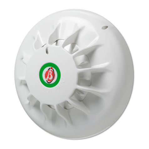
The FC400 Series Detectors, as supplied, use a common
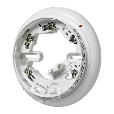
FC450IB Isolator Base assembly. Guidance on mounting and wir-
ing a FC450IB Isolator Base is given below.
FIXING THE DECTOR BASE
The base may be fixed directly to:
ØBritish (fixing centres 50mm) or European (fixing centres
70mm) conduit box;
ØFC450EMB Euro Mounting Box;
ØDirectly to the ceiling.
DETECTOR LOCATION
The location of each detector should have been determined at the
system design stage in accordance with the site plan. The detec-
tor bases must be mounted in accordance with this plan. If prob-
lems arise then reference to the system designer must be made.
The detector base does not need aligning as the detector LED is
visible through 360°. However, the short circuit indicator needs to
be visible for fault location.
FIXING THE DETECTOR BASE
nTO A CONDUIT BOX
The detector base is to be secured directly to the conduit box with
two M4 pan head steel screws, zinc plated and passivated. The
fixing slot allows the mounting to be fitted to both B.E.S.A. conduit
boxes having fitting points at 50mm centres and European conduit
boxes with fitting points at 70mm centres. For ease of fixing, there
are enlarged holes on the fixing slots, which allows the first fixing
screw to be inserted loosely, the base is then fitted to the screw.
nTO OTHER SURFACES
The detector base is to be secured with two No. 8 x 1 inch pan
head steel screws zinc plated and passivated or equivalent at the
fixing centres shown in Fig. 1.The surface chosen for the mounting
should be flat over the area of the base to ensure a stable fixing.
ENGLISH
INDICATORE DI CORTO
CIRCUITO
SHORT CIRCUIT INDICATOR
LED ZUR
KURZSCHLUSSANZEIGE
CHIAVE DI
BLOCCAGGIO
LOCKING KEY
SPERRE
PERNO PER IL PARCHEGGIO
TEMPORANEO
TEMPORARY PARK
STIFT DRÜCKEN, DANN MELDER IN
PARKPOSITION DREHEN
RIFERIMENTO RIALZATO
RAISED RIB
MARKIERUNG FÜR MELDER IN
BETRIEBSPOSITION
SEDE CHIAVE DI BLOCCAGGIO
LOCKING KEY SLOT
OPTIONALE SPERRE EINFÜGEN
FIG. 2 FC450IB Isolator Base *Patented
POSIZIONAMENTO FORI PER VITI
SCREW LOCATING HOLES
MONTAGELÖCHER
FIG. 1 Fixing Dimensions for Detector Base
nCONNECTOR IDENTIFICATION
The FC450IB Isolator Base has five terminals:
RRemote LED connector
LNot connected
L1 +ve IN/OUT
L2 -ve OUT
M-ve IN
nFITTING OF LOCKING DEVICE
Figs. 2 and 6 refer. To fit the locking key, break it off from the sprue
connecting it to the body moulding. Fit the locking device in the
orientation shown in Fig. 6 and push firmly in.
other end of the loop or any base along the loop to verify the wir-
ing up to that point. If there is no voltage out at any measured
point, this may be due to:
1) Loop Open Circuit - wiring incomplete to part of the loop.
2) Incorrect Polarity -FC450IB Isolator bases will appear as a
short circuit if they are wired with incorrect polarity.
3) Loop Short Circuit - If this occurs between two FC450IB Isola-
tor bases, it will isolate that section of the line, which will then
appear as an open circuit. If this occurs between the supply
and the first FC450IB Isolator Base, the supply output will go
low due to the internal current limit.
APERTURA LED
LED APERTURE
TAPPO APERTURA LED
LED APERTURE PLUG
DISPOSITIVO DI BLOCCAGGIO
LOCKING DEVICE
FORI POSIZIONAMENTO VITI
SCREW LOCATING HOLES
SEDE DISPOSITIVO DI BLOCCAGGIO
LOCKING DEVICE SLOT
FIG. 3 Part identification
APERTURE DI FISSAGGIO
MOUNTING SLOTS
MORSETTO ACCESSORIO
PER LA BASE (BATs)
(di fabbrica, inserito solo
in una posizione)
BASE ACCESSORY
TERMINAL (BATs)
(factory fitted in
one position only)
NOTA: ULTERIORI MORSETTI POSSONO ESSERE ORDINATI IN BASE ALLE NECESSITÀ
NOTE: EXTRA BATs MAY BE ORDERED TO PROVIDE ADDITIONAL CABLE TERMINALS
FIG. 4 FC450EMB Euro mounting box
5B 5B
5B
FC
L1
L1
L1
L1
RIGHT
LEFT
FIG. 5 Simplified Circuit Diagram
nFITTING/REMOVAL OF A DETECTOR
1) Stick the address number labels to the Address Flag and de-
tector.
2) Fit the Address Flag to the detector as shown in Fig. 7.
3) Place the detector onto the base and turn until it locates on the
base, then turn clockwise until fully located (the raised ribs of
the base and detector are aligned).
4) If the detector is removed, the Address Flag will remain with the
base, ensuring that detectors are not accidentally returned to
the wrong base.
5) When a locking key has been inserted into the base, the detec-
tor may only be removed by using a lock release tool to de-
press the locking pin.
6) The temporary park plunger is used to allow the detector to be
placed in a park position once mounted to the base. This al-
lows the detector to be turned anti clockwise past the location
position to break electrical contact with the base. This means
the cabling to the detector may be tested with the detector
mounted to the base.
nCOMMISSIONING
Commission the fitted detector as detailed in Installation/Commis-
sioning document.
ORDERING INFORMATION
FC450IB: 5" Isolator Base

FC450EMB: Euro Mounting Box
Base AccessoryTerminal (pack of 10)
RECYCLING INFORMATION
Customers are recommended to dispose of their used equipments
(panels, detectors, sirens, and other devices) in an environmentally
sound manner. Potential methods include reuse of parts or whole
products and recycling of products, components, and/or materials.
WASTE ELECTRICAL AND ELECTRONIC EQUIPMENT
(WEEE) DIRECTIVE
In the European Union, this label indicates that this
product should NOT be disposed of with household
waste. It should be deposited at an appropriate facility
to enable recovery and recycling.
The manufacturer reserves the right to change the technical speci-
fications of this product without prior notice.
FIG. 6 Fitting of Locking Device
INCAVI DI BLOCCAGGIO
RETAINING DEPRESSIONS
RIENTRANZA DI MONTAGGIO
MOUNTING RECESS
PARTE SAGOMATA A ´D`
´D` SHAPED PART
CANALE SAGOMATO A ´U`
´U` SHAPED CHANNEL
SPORGENZE DI BLOCCAGGIO
RETAINING PIMPLES
FIG. 7 Fitting Address Flag

This manual suits for next models

1

Other Bentel Security Security Sensor manuals

Bentel Security BW-MCN User manual

Bentel Security

Bentel Security BW-MCN User manual

Bentel Security DT800 User manual

Bentel Security

Bentel Security DT800 User manual

Bentel Security FC400H User manual

Bentel Security

Bentel Security FC400H User manual

Bentel Security RAY60 User manual

Bentel Security

Bentel Security RAY60 User manual

Bentel Security ZT100H User manual

Bentel Security

Bentel Security ZT100H User manual

Bentel Security BL151 User manual

Bentel Security

Bentel Security BL151 User manual

Bentel Security DT800 User manual

Bentel Security

Bentel Security DT800 User manual

Bentel Security AMC10 User manual

Bentel Security

Bentel Security AMC10 User manual

Bentel Security Visus99 User manual

Bentel Security

Bentel Security Visus99 User manual

Bentel Security BMD503 User manual

Bentel Security

Bentel Security BMD503 User manual

Bentel Security RAY60-S User manual

Bentel Security

Bentel Security RAY60-S User manual

Bentel Security IR 360 User manual

Bentel Security

Bentel Security IR 360 User manual

Bentel Security FC450IB User manual

Bentel Security

Bentel Security FC450IB User manual

Popular Security Sensor manuals by other brands

Texecom Prestige AMDT Plus installation instructions

Texecom

Texecom Prestige AMDT Plus installation instructions

Computherm HT-3000 operating instructions

Computherm

Computherm HT-3000 operating instructions

STEINEL PROFESSIONAL IR Micro Information

STEINEL PROFESSIONAL

STEINEL PROFESSIONAL IR Micro Information

Niko 351-25456 user manual

Niko

Niko 351-25456 user manual

teko Astra-517 operating manual

teko

teko Astra-517 operating manual

Graco Husky A Series instructions

Graco

Graco Husky A Series instructions

Electra e3 manual

Electra

Electra e3 manual

Optex AX-70TN installation manual

Optex

Optex AX-70TN installation manual

hyfire TAURUS TAU-OP-01 quick start guide

hyfire

hyfire TAURUS TAU-OP-01 quick start guide

LEGRAND Celiane 676 61 instructions

LEGRAND

LEGRAND Celiane 676 61 instructions

SICK Prime KTX-WN92141252ZZZZ manual

SICK

SICK Prime KTX-WN92141252ZZZZ manual

Inficon D-TEK 3 quick start guide

Inficon

Inficon D-TEK 3 quick start guide

industrie technik SEW-PT1000 instructions

industrie technik

industrie technik SEW-PT1000 instructions

Endres Soliphant T FTM20 manual

Endres

Endres Soliphant T FTM20 manual

Extel HEO Installation and user guide

Extel

Extel HEO Installation and user guide

PCB Piezotronics IMI Sensors RV640B11 Installation and operating manual

PCB Piezotronics

PCB Piezotronics IMI Sensors RV640B11 Installation and operating manual

CPVan CP-D10 quick start guide

CPVan

CPVan CP-D10 quick start guide

MSA AUER VAUTEX SL-S manual

MSA AUER

MSA AUER VAUTEX SL-S manual

manuals.online logo
manuals.online logoBrands
  • About & Mission
  • Contact us
  • Privacy Policy
  • Terms and Conditions

Copyright 2025 Manuals.Online. All Rights Reserved.