Berner Deco-Tube Series Service manual

I
D
f
v
A
s
t
I
f you smel
l
1. Shut
o
2. Extin
g
3. If odo
u
call y
o
F
O
D
o not stor
e
f
lammable
v
v
icinity of t
h
A
n LP cylin
s
hall not b
e
t
his or any
o
I
n
DAN
G
l
gas:
o
ff gas to a
p
g
uish any o
p
u
r continue
o
ur gas sup
O
R YOUR
e
or use g
a
v
apours a
n
h
is or any
o
der not co
n
e
stored in
t
o
ther appli
a
n
stalla
t
WA
R
G
ER
p
pliance.
p
en flame.
s
, immedia
plier.
SAFETY
a
soline or o
n
d liquids in
o
ther applia
n
nected for
t
he vicinity
o
a
nce.
t
ion, O
p
R
NING:F
O
tely
ther
the
nce.
use
o
f
p
eratio
n
Retain t
Improper i
n
service or
property d
a
and maint
e
installing
o
O
R OUTDO
O
Installer m
owner. On
should pe
r
n
and
S
O
t
hese instr
u
n
stallation,
maintenan
c
a
mage. Re
e
nance ins
t
o
r servicing
OR USE
O
IN
S
ust leave t
h
ly those w
h
r
form servi
c
S
ervice
O
WNER:
u
ctions for
f
WARNIN
G
adjustmen
c
e can cau
e
ad the inst
a
t
ructions th
this equip
m
O
NLY
S
TALLER:
h
ese instru
c
h
o are certi
f
c
e on thes
e
Instru
c
f
uture refer
e
G
:
t, alteratio
n
se injury o
r
a
llation, op
oroughly b
e
m
ent.
ctions with
f
ied to do
s
e
heaters.
c
tions
e
nce.
n
,
r
erating
e
fore
the
s
o
Series Deco-Tube
Model BTD-ETO100
Infrared Patio Heater

2 APRIL/25/2013
SERIES DECO-TUBE

SERIES DECO-TUBE3 APRIL/25/2013
Table of Contents
CAUTION AND GENERAL SAFETY.............................................................................................................4
SAFETY REQUIREMENTS.............................................................................................................................................4
GENERAL ................................................................................................................................................5
INSTALLATION CODES................................................................................................................................................5
GENERAL INSTALLATION AND GAS CODES.....................................................................................................................5
GAS SUPPLY LINES ....................................................................................................................................................5
ELECTRICAL..............................................................................................................................................................5
SPECIFICATIONS......................................................................................................................................6
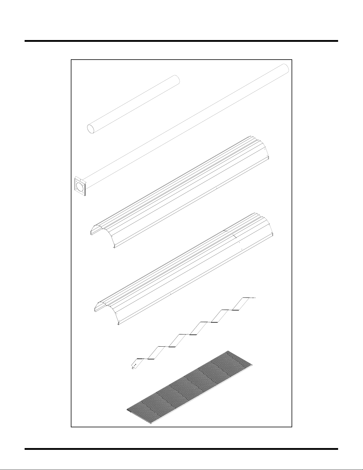
HEATER COMPONENTS:.............................................................................................................................................6
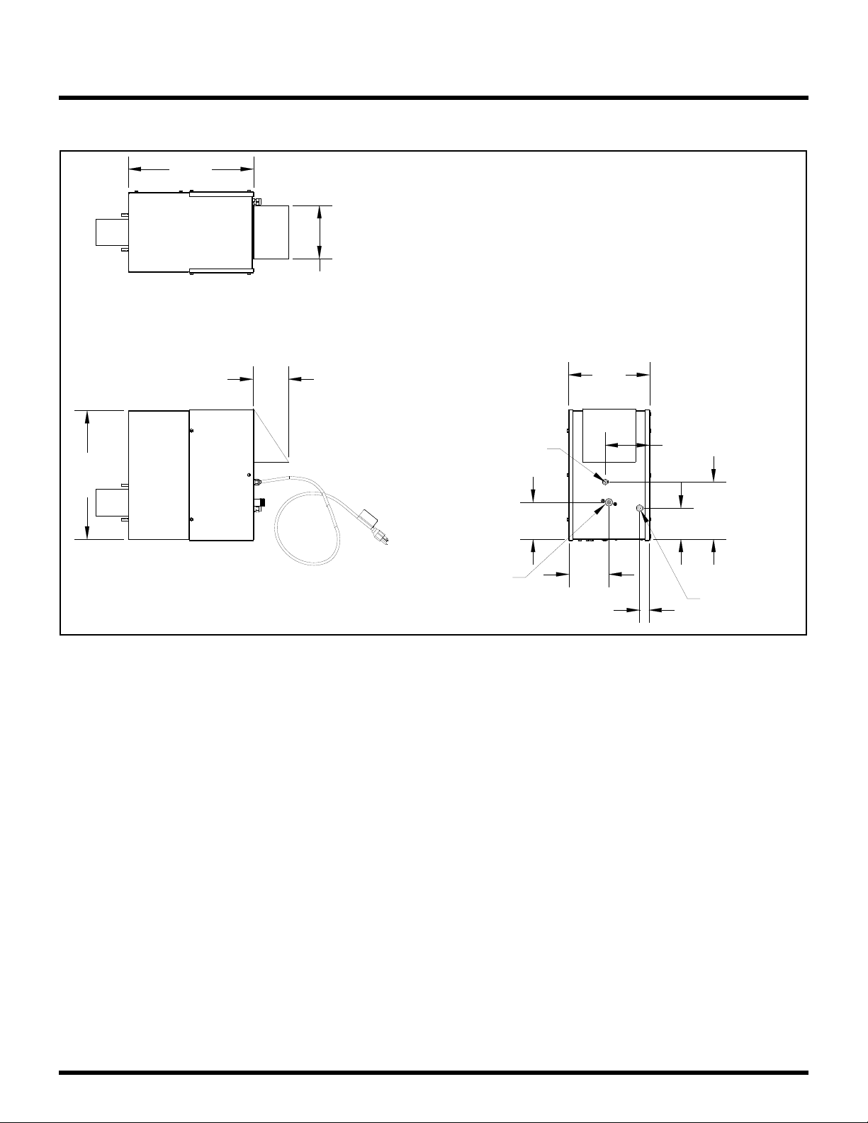
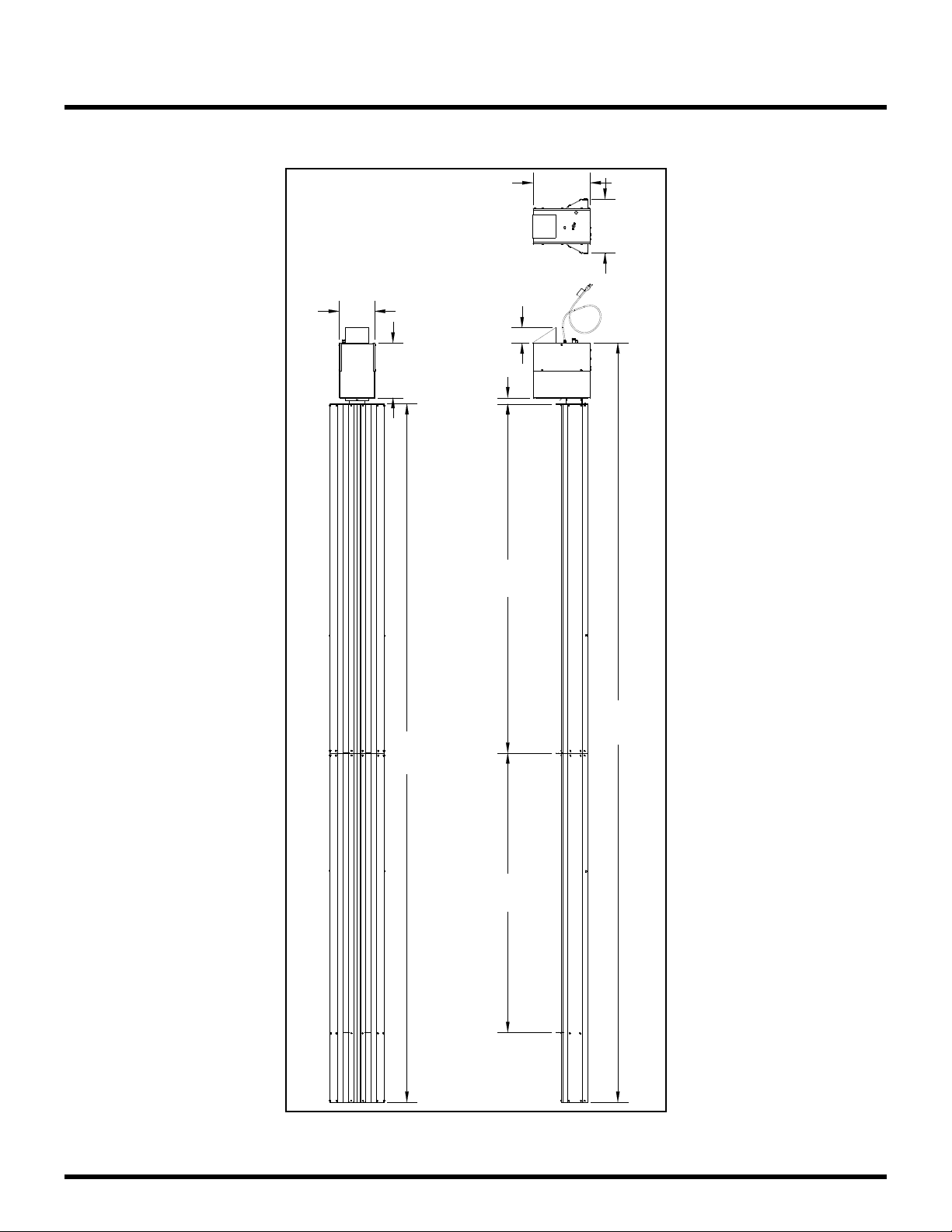
DIMENSIONAL DETAILS:.............................................................................................................................................8
INSTALLATION REQUIREMENTS ............................................................................................................10
POWER &GAS SPECIFICATIONS ................................................................................................................................10
CLEARANCE TO COMBUSTIBLES .................................................................................................................................11
HEATER MOUNTING ...............................................................................................................................................13
INSTALLATION INSTRUCTIONS..............................................................................................................14
INSTALLATION SEQUENCE: .......................................................................................................................................14
STANDARD FREEHANGING INSTALLATION .................................................................................................................14
DROP CEILING INSTALLATION: ..................................................................................................................................28
VENTING...............................................................................................................................................................31
GAS CONNECTIONS...............................................................................................................................32
INSTALLATION /CODE REQUIREMENTS....................................................................................................................... 32
WIRING DIAGRAMS ..............................................................................................................................33
GENERAL REQUIREMENTS ........................................................................................................................................33
EXTERNAL WIRING OPTIONS ....................................................................................................................................35
LIGHTING & SHUTDOWN INSTRUCTIONS..............................................................................................36
LIGHTING ..............................................................................................................................................................36
SHUT DOWN.........................................................................................................................................................36
MAINTENANCE & TROUBLE SHOOTING ................................................................................................37
MAINTENANCE.......................................................................................................................................................37
TROUBLE SHOOTING ...............................................................................................................................................37
TROUBLESHOOTING CHART......................................................................................................................................39
PARTS LIST............................................................................................................................................40
WARRANTY ..........................................................................................................................................41

4 APRIL/25/2013
Caution and General Safety
At all times maintain clearance to combustible materials as further specified in this manual.
Failure to do so can result in serious fire hazard.
Never operate heaters in atmosphere containing flammable vapours or combustible dusts.
This heater is equipped with an electronic and automatic ignition device. Do not attempt to
light the burner by hand. Failure to comply can result in a serious fire and personal injury
hazard.
Certain materials, when stored under this heater are subjected to radiant heat can soften,
distort or otherwise be damaged, special care should be taken of plastic materials
Appliance surfaces, other than the obvious flame and emitter surfaces, attain elevated
temperatures during operation. Do not touch the heater head during operation. Everyone
should be alerted to this hazard to avoid burning.
Children should be strictly supervised when in the area of this heating appliance. Playing or
running around the structure should be strictly forbidden.
Clothing or other flammable materials should not be hung on or near this heater.
Any guard or other protective device removed for servicing the heater must be replaced
prior to operating the heater.
Installation and repair should be done by a qualified service person. The heater should be
inspected before use and at least annually by a qualified service person.
Safety Requirements
1. Never locate the heater directly below electrical lines, gas lines or sprinkler systems.
2. Do not locate heater too close to vinyl or plastic wall coverings. These materials may
discolour or soften well before they reach combustible limits.
3. The heater requires a minimum clearance from combustible materials. See the
Clearance to Combustible Materials section for specific requirements.
4. Always allow room for maintenance purposes.
5. The heater aspirates air for combustion. Do not locate heater where there are severe
draft conditions or airflow restrictions to the burner.
CAUTION: FIRE OR BURN INJURY HAZARD
SERIES DECO-TUBE

5 APRIL/25/2013
General
Installation Codes
Installations must comply with local building codes, or in their absence, the latest edition of the
national regulations and procedures as listed below.
General Installation and Gas Codes
Heaters must be installed only for use with the type of gas appearing on the rating plate, and the
installation must conform to the National Fuel Gas Code, ANSI Z223.1/NFPA 54 in the US and
CAN/CGA B149.1 and B149.2 Installation Codes in Canada.
This heater maybe approved for either indoor or outdoor installation. Not for use in residential
dwellings, refer to Rating plate.
Gas SupplyLines
Gas supply pipe sizing must be in accordance with the National Fuel Gas Code, ANSI
Z223.1/NFPA 54 in the US and CAN/CGA B149.1 and B149.2 Installation Codes in Canada.
A 1/8" NPT plugged tap must be installed in the gas line connection immediately upstream of the
burner farthest from the gas supply meter to allow checking of system gas pressure.
Electrical
All heaters must be electrically grounded in accordance with the National Electric Code,
ANSI/NFPA 70 in the US, and the Canadian Electric Code, CSA C22.1 in Canada, and must
comply with all local requirements.
SERIES DECO-TUBE

6 APRIL/25/2013
Specifications
Heater Components:
Heater
5/16 Nut
QTY (4)
5/16 Lock
Washer
QTY (4)
Burner
Hanger
QTY (1)
Middle
Hanger Ass'y
QTY (1)
Vent
Hanger
QTY (1)
#8-32 x 3/8"
Screws
QTY (42)
Gasket
QTY (1)
Coupling
QTY (1)
Vent
Terminal
Assembly
QTY (1)
#8 X 1/2"
screws
Self drilling
QTY (2)
Deco Grille
Supports
QTY (2)
#8 X 1/2"
Spring
Clip
QTY (4)
End
Cap
QTY (1)
SERIES DECO-TUBE

7 APRIL/25/2013
Specifications
Heater Components continued:
10' Flanged
Tube
QTY (1)
4' Extension
Tube
QTY (1)
Primary
Reflector
QTY (1)
Secondary
Reflector
QTY (1)
Deco-Grille
QTY (3)
6' Baffle
QTY (1)
SERIES DECO-TUBE

8 APRIL/25/2013
Specifications
Dimensional Details:
Note: All dimensions are in inches.
6.5
Electrical
Cord Location 5.0
Gas
inlet
Location
9.1
Thermostat
Connection
4.2
4.5
1.1
3.5
14.5
4.0
14.1
6.0
SERIES DECO-TUBE

9 APRIL/25/2013
Specifications
Dimensional Details continued:
Note: All dimensions are in inches.
9.2
180.1
14.8
13.9
195.9
4.0
14.1
1.690.072.0
SERIES DECO-TUBE

10 APRIL/25/2013
Installation Requirements
Power & Gas Specifications
Gas Supply
Rated Input Hi Fire Low Fire
100,000 BTU 75,000 BTU
Inlet Pressure Natural Gas: Propane Gas:
Min. 5.0” W.C. 11.5” W.C.
Max. 14.0” W.C. 14.0” W.C.
Manifold Pressure Natural Gas: Propane Gas:
High Rate 3.3” W.C. 10.2” W.C.
Low Rate 2.0” W.C. 6.4” W.C.
Inlet Connection Natural Gas: Propane Gas:
½” Female NPT ½” Female NPT
Electrical Supply
120 VAC, 60Hz. 1Amp: 72” Cord with grounded 3 prong plug.
Important
Installation or repair should only be done by a qualified service person. The heater should
be inspected before use and at least annually by a qualified service person.
The appliance and its individual shutoff valve must be disconnected from the gas supply
piping system during any pressure testing of that system at test pressures in excess of ½
psig (3.5 kPa)
The appliance must be isolated from the gas supply piping system by closing its individual
manual shutoff valve during any pressure testing of the gas supply piping system at test
pressures equal to or less than ½ psig (3.5 kPa)
SERIES DECO-TUBE

11 APRIL/25/2013
Installation Requirements
Clearance to Combustibles
A general clearance of 18” (0.5 m) in every direction is recommended for servicing only around
each Burner, also to ensure adequate air flow in and around the Heating System.
In addition to this it is very important to observe the minimum clearance to combustibles at
all times to avoid any possibility of property damage or personal injury.
Table below lists the minimum clearance to combustible materials for various installation
configurations. Additional clearance may be required for glass, painted surfaces and other
materials which maybe damaged by radiant or convective heat.
Combustible materials are considered to be wood, compressed paper, plant fibres, plastics,
Plexiglas or other materials capable of being ignited and burned. Such materials shall be
considered combustible even though flame-proofed, fire-retardant treated or plastered.
Adequate clearance to sprinkler heads must be maintained.
The stated clearance to combustibles represents a surface temperature of 90°F (50°C) above
room temperature. Building materials with low heat tolerance (such as plastics, vinyl siding,
canvas, tri-ply, etc…) maybe subject to degradation at lower temperatures. It is the installer’s
responsibility to assure that adjacent materials are protected from degradation.
Note with an ambient temperature of 70°F the surface temperatures at the clearance
distances listed below could reach 160°F, Care should be taken with placement of plastic or
vinyl in the proximity of the heater as they tend to distort and soften at these temperatures.
NOTE: Sprinkler head heat fuse link performance may alter with age.
SERIES DECO-TUBE

12 APRIL/25/2013
Installation Requirements
Model No.:
Reflector Configurations Dim ETO-100
Horizontal
B D
C
AA
B
C
D
4"
29"
73.5"
29"
45° Reflector Tilt
B
D
C
AA
B
C
D
8"
2.5"
55.5"
43"
Ends (both sides) ”4
This heater can be installed between wood beams with minimum distances as shown. Air flow
MUST NOT .detcirtsereb
NOTE: Some materials deteriorate or soften at sustained temperatures below 160°F.
Consult material manufacturer for recommendations
1/2"
Trusses CAN'T be inclosed
Wood Beam
1/2"
SERIES DECO-TUBE

13 APRIL/25/2013
Installation Requirements
Heater Mounting
RECOMMENDED hanging equipment needed to install the heater.
In all cases, check with local codes for seismic bracing requirements for outdoor heating
equipment.
In these instructions we illustrate installation with angles and a combination of angles and
turnbuckles. Other methods such as chain and appropriate bracing can be incorporated as an
alternative. The heater must be prevented from swaying and putting stress on the gas connection.
The installer is responsible for adequate bracing.
Close all open ended S hooks and turnbuckles to avoid unhooking chain with inadvertent
contact.
Note: Minimum mounting height is 7’ in Canada and 8’ in the US.
Turnbuckle Angle Iron
Min. working
load 200 lb.
for turnbuckle.
Min. 1 12x 1 12
14 Ga. angle iron
SERIES DECO-TUBE

14 APRIL/25/2013
Installation Instructions
Installation Sequence:
Generally, there is no unique sequence for installation of the burner or heat exchanger. A review
of the job site will usually indicate a logical installation order. However, time and expense can be
saved if installation is begun at the most critical dimension, watching for interference from
overhead beams etc.
It is RECOMMENDED to follow the installation sequence shown in the following pages.
Standard FREE Hanging Installation
Step 1:
90.0
72.0
Angle iron
- Anchor angle irons at specified
distances to ceiling.
- Use turnbuckles or angle irons
to mount heater to anchored
angles as shown in manual.
Anchor this angle
iron as shown.
Note:
Burner side
Note:
Burner end / Vent side
SERIES DECO-TUBE

15 APRIL/25/2013
Installation Instructions
Step 2:
Step 3:
90.0"
60.0"
Pipe
stand
Pipe
stand
Flanged
tube
SERIES DECO-TUBE

16 APRIL/25/2013
Installation Instructions
Step 4:
Step 5:
Burner
hanger
Middle
hanger
assembly
Burner
hanger
SERIES DECO-TUBE

17 APRIL/25/2013
Installation Instructions
Step 6:
Step 7:
Middle
hanger
assembly
Burner
hanger
Coupling
SERIES DECO-TUBE

18 APRIL/25/2013
Installation Instructions
Step 8:
Step 9:
When installing, orient band
clamp lock bolts to side at
3 o'clock or 9 o'clock position to
avoid contact with reflector.
Torque to
15-25 ft-lbs
4' Extension
tube
Vent
hanger
SERIES DECO-TUBE

19 APRIL/25/2013
Installation Instructions
Step 10:
Step 11:
Primary
Reflector
SERIES DECO-TUBE

20 APRIL/25/2013
Installation Instructions
Step 12:
Step 13:
Slide reflector
and hanger
against flange
#8-32 X 3/8"
screws
SERIES DECO-TUBE
This manual suits for next models
1
Table of contents
Other Berner Patio Heater manuals
Popular Patio Heater manuals by other brands

DCS
DCS PHFS-P4 Use and care and installation guide

Outdoor Leisure
Outdoor Leisure TD113 owner's manual

Campfire in a can
Campfire in a can Patio Heater owner's manual

Prem-I-Air
Prem-I-Air EH0369 quick start guide

HEAT1
HEAT1 ECO plus-line LDHR005G2-200KY-M instructions

EvenGlo
EvenGlo GA201M2 Installation, operation and service instructions

Gasmate
Gasmate PH2063 Installation, operation and maintenance instructions

Blumfeldt
Blumfeldt Gold Bar 2000 Swing manual

Charmglow
Charmglow 82300 owner's manual

empasa
empasa Hexa Flame CZGB-S Assembly and operation manual

Tahoe
Tahoe 40101300 instruction manual

Clatronic
Clatronic THS 3541 instruction manual