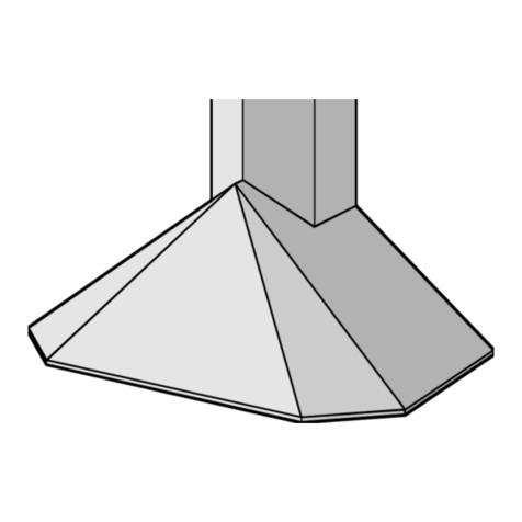
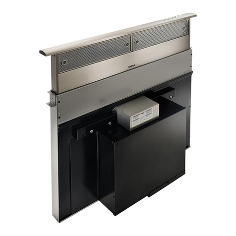
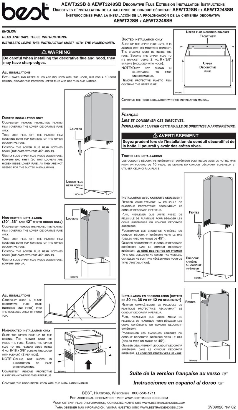
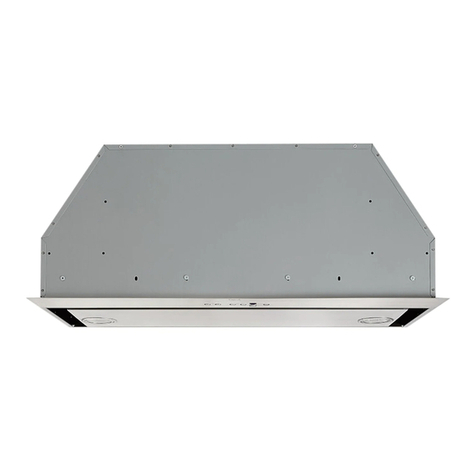
Best K7788 User manual

BEST BY BROAN P.O. Box 140, Hartford, WI 53027
Model K7788
ENGLISH.....................................3
FRANÇAIS................................15
ESPAÑOL.................................27

- 2 -

- 3 -
READ AND SAVE THESE INSTRUCTIONS
WARNING
TO REDUCE THE RISK OF FIRE, ELECTRICAL SHOCK, OR INJURY TO PERSONS,
OBSERVETHEFOLLOWING:
1. Usethis unit onlyin the mannerintended by themanufacturer. If youhave questions,
contactthemanufacturer at theaddressortelephone number listed inthewarranty.
2. Before servicing or cleaning unit, switch power off at service panel and lock service
panel to prevent power from being switched on accidentally. When the service
disconnectingmeans cannot belocked, securely fastena prominent warningdevice,
suchas a tag,to the servicepanel.
3. Installation work and electrical wiring must be done by a qualified person(s) in accor-
dancewith all applicable codesandstandards,including fire-rated constructioncodes
andstandards.
4. Sufficientair is needed for proper combustion and exhaustingofgasesthroughtheflue
(chimney)offuelburning equipment to preventbackdrafting.Followtheheatingequip-
mentmanufacturer’s guidelines andsafety standards suchas those publishedbythe
National Fire Protection Association (NFPA), and the American Society for Heating,
RefrigerationandAirConditioningEngineers(ASHRAE),andthelocalcodeauthorities.
5. When cutting or drilling into wall or ceiling, do not damage electrical wiring and other
hiddenutilities.
6. Ductedfans must alwaysbevented to theoutdoors.
7. Donot use thisunitwith any solid-state speedcontroldevice.
8. Toreduce the riskof fire, useonlysteel ductwork.
9. Thisunit must be grounded.
TOREDUCETHERISKOFA RANGE TOP GREASE FIRE:
A. Never leave surface units unattended at high settings. Boilovers cause smoking and greasy
spillovers that may ignite. Heat oils slowly on low or medium settings.
B. Always turn hood ON when cooking at high heat or when cooking flaming foods.
C. Clean ventilating fans frequently. Grease should not be allowed to accumulate on fan or
filter.
D. Use proper pan size. Always use cookware appropriate for the size of the surface element.
WARNING
TOREDUCE THE RISKOFINJURY TO PERSONSIN THE EVENT OFA RANGE TOP
GREASEFIRE,OBSERVETHEFOLLOWING:*
1. SMOTHERFLAMESwith a close-fitting lid, cookie sheet, or metal tray,thenturnoffthe
burner.BECAREFULTO PREVENT BURNS. Iftheflamesdonotgo out immediately,
EVACUATEANDCALLTHEFIREDEPARTMENT.
2. NEVERPICK UP A FLAMING PAN-Youmaybeburned.
3. DONOT USE WATER, including wet dishcloths ortowels-violentsteamexplosionwill
result.
4. Usean extinguisher ONLY if:
A. YouknowyouhaveaClassABCextinguisherand you already knowhowtooperate
it.
B. Thefire is smallandcontainedin the areawhere itstarted.
C. Thefire department is being called.
D. Youcan fightthefire with yourbackto an exit.
*Basedon “Kitchen Fire SafetyTips”publishedby NFPA.
!
INTENDED FOR DOMESTIC COOKING ONLY.
!

- 4 -
!
CAUTION
1. Toreducerisk of fire and to properly exhaust air, besure to duct air outside. Donot vent
exhaustair into spaces withinwallsor ceilings orintoattics, crawl spaces,orgarages.
2. Takecare when usingcleaning agentsordetergents.
3. Avoidusing food products thatproduce flamesunder theRangeHood.
4. Forgeneralventilating use only.Donotusetoexhaust hazardous orexplosivematerials
andvapors.
5. Toavoid motor bearingdamageand noisy and/orunbalancedimpellers, keep drywall
spray,construction dust, etc.off power unit.
6. Yourhood motor hasa thermaloverloadwhich will automatically shutoffthe motor if it
becomesoverheated.The motor will restartwhen itcools down.Ifthemotor continues
toshut off andrestart, have thehoodserviced.
7. Forbest capture ofcooking impurities,thebottom of the hoodshouldbe a minimum of
24"and a maximumof 30" abovethecooking surface. See“Install Mounting Bracket”
sectionformounting restrictions.
8. Twoinstallers are recommended becauseofthelarge size and weightofthishood.
9. This product is equipped with a thermostat which may start blower automatically. To
reduce the risk of injury and to prevent power from being switched on accidentally,
switchpower off atservice panel andlockor tag servicepanel.
10.Use with approved cord-connectionkitonly.
11. Pleasereadspecificationlabelonproductforfurther information and requirements.

- 5 -
OPERATION
Controls
The hood is operated using the (4) push-
buttonslocatedateye-level, onthe frontedge
of the hood.
The light switch turns the halogen lights
on and off. Push the light switch once to
turn the lights ON - push a second time to
turn the lights ON to a brighter level - push a
third time to turn the lights OFF.
The timer switch turns the blower timer on and off. Push this switch once to turn the
timer ON. With the blower timer turned ON, the speed that was selected will blink in
the display; if the speed selection is changed the blower timer will remain ON; the
blower will shut OFF after 10 minutes.
The display indicates:
- indicates the selected motor speed (from 1 to 4);
- indicates Timer On when the number blinks;
- indicates Filter Alarm when the central segments is on or blinking.
The blower switch turns the blower on and off. Push the switch once to turn the
blower ON (turns on to last speed selected). Pushing the switch sequentially selects
blower speeds from 1 to 4. To turn OFF the blower, push and hold the blower switch
for approximately 2 seconds.
The reset switch resets the grease filter or charcoal filter alarm. The grease filter
must be cleaned when the center segment of the display lights up continuously or
blinks. The filter alarm will be seen in the DISPLAY for approximately 30 seconds
after the blower is turned off. To reset the hour counter, keep the switch pressed for
2 seconds when the alarm can be seen in the DISPLAY.
HEAT SENTRY™
Your hood is equipped with a HEAT SENTRY™ thermostat. This thermostat is a
device that will turn on or speed up the blower if it senses excessive heat above
the cooking surface.
1) If blower is OFF - it turns blower ON to HIGH speed.
2) If blower is ON at a lower speed setting - it turns blower up to HIGH speed.
When the temperature level drops to normal, the blower will return to its original
setting.
WARNING
The HEAT SENTRY thermostat can start the blower even if the hood is turned
OFF. When this occurs, it is impossible to turn the blower OFF with its switch.
If you must stop the blower, do it from the main electrical panel.
LIGHT
SWITCH
TIMER
SWITCH
RESET
SWITCH
DISPLAY
BLOWER
SWITCH

- 6 -
FUSE REPLACEMENT
IFLIGHTSFAILTOOPERATE,DISCONNECT
THEPOWERATTHESERVICEENTRANCE.
CHECK THE FUSE AND REPLACE IF
NECESSARY.
1. Remove the decorative flue. Fig. 2
2. Remove the cover from the large
electrical wiring box.
3. Locate the fuse holder. Unscrew its cap
and remove the fuse.
4. Replace the fuse with the same size and
amperage (5x20mm, 4amp, 125volt).
5. Reinstall the electrical box cover and
decorative flue.
6. Reconnect power at the service
entrance.
FUSE
ELECTRICALBOX
HALOGEN BULBS
This range hood requires two halogen bulbs
(Type T4, 12V, 20W).
ALWAYS SWITCH OFF THE ELECTRICAL
SUPPLY BEFORE CARRYING OUT ANY
OPERATIONSONTHEAPPLIANCE.
To change bulbs:
1. Open the cover by prying from the proper
slots. - DO NOT ROTATE. CAUTION:
BULBMAYBEHOT! Fig.1
2. Replace with a Type T4, 12V, 20W bulb.
Do not touch replacement bulb with bare
hands!
FIG. 1
FIG. 2
DECORATIVE FLUE

- 7 -
CLAMP
TABS
MAINTENANCE
Proper maintenance of the Range Hood will
assure proper performance of the unit.
Grease Filters
Grease filters should be cleaned when the
light switch flashes or remains lit when the
blower is off (i.e. 30 hours of operation). Use
a warm detergent solution to clean filters.
Filters are dishwasher safe. See page 14 for
filter removal and installation instructions.
Non-ductedRecirculation Filter
The non-ducted recirculation filter should
be changed when the light switch flashes or
remains lit when the blower is off (i.e. 120
hours of operation). See page 14 for filter
removal and installation instructions.
HoodCleaning
Stainless steel is one of the easiest materials
to keep clean. Occasional care will help pre-
serve its fine appearance.
Cleaning tips:
●Hot water with soap or detergent is all that
is usually needed.
●Follow all cleaning by rinsing with clear water. Wipe dry with a clean, soft cloth to
avoid water marks.
●Fordiscolorationsordepositsthatpersist,use anon-scratching householdcleanser
or stainless steel polishing powder with a little water and a soft cloth.
●For stubborn cases, use a plastic scouring pad or soft bristle brush together with
cleaser and water. Rub lightly in direction of polishing lines or "grain" of the
stainless finish. Avoid using too much pressure which may mar the surface.
●DO NOT allow deposits to remain for long periods of time.
●DO NOT use ordinary steel wool or steel brushes. Small bits of steel may adhere
to the surface causing rust.
●DO NOT allow salt solutions, disinfectants, bleaches, or cleaning compounds to
remain in contact with stainless steel for extended periods. Many of these com-
pounds contain chemicals which may be harmful. Rinse with water after expo-
sure and wipe dry with a clean cloth.
Painted surfaces should be cleaned with warm water and mild detergent only.
GREASE
FILTERS
NON-DUCTED
RECIRCULATION
FILTER

- 8 -
PREPARE THE HOOD
Unpack hood and check contents.
You should receive:
1 - Hood
1 - Decorative Flue Assembly
1 - Parts Bag containing:
1 - Mounting Bracket
1 - Discharge Collar
1 - Flue Mounting Bracket
6 - Mounting Screws (4.8 x 38mm Pan Head)
5 - Mounting Screws (3.9 x 9.5mm Pan Head)
2 - Bracket Screws (3.9 x 5.7mm Flat Head)
6 - Drywall Anchors
1 - Installation Instructions
1 - Warranty Card
MOUNTING
BRACKET
DISCHARGE
COLLAR
FLUE MOUNTING
BRACKET 6 MOUNTING SCREWS
(4.8 x 38mm Pan Head) 6 DRYWALL
ANCHORS
5 MOUNTING SCREWS
(3.9 x 9.5mm Pan Head)
DECORATIVE
FLUE
2 BRACKET SCREWS
(3.9 x 5.7mm Flat Head)

- 9 -
ROOF CAP
ROUND DUCT
DECORATIVE
FLUE
HOOD
WALL
CAP
ROUND
ELBOW
24” TO 30” ABOVE
COOKING SURFACE
(See “INSTALL MOUNTING
BRACKET” SECTION,
page 10, for mounting
restrictions)
INSTALL THE DUCTWORK
(DUCTEDHOODSONLY)
NOTE: To reduce the risk of fire, use only
metal ductwork.
1. Decide where the ductwork will run
between the hood and the outside.
2. Astraight,shortductrunwill allowthehood
to perform most efficiently.
3. Long duct runs, elbows, and transitions
will reduce the performance of the hood.
Use as few of them as possible. Larger
ducting may be required for best
performance with longer duct runs.
4. Install a roof or wall cap. Connect round
metal ductwork to cap and work back to-
wardshoodlocation. Useducttapeto seal
the joints between ductwork sections.
6”
ADAPTER
INSTALL ELECTRICAL
WARNING: Electrical wiring must be
done by a qualified person(s) in
accordance with all applicable codes and
standards. This range hood must be
properly grounded. Turn off electrical
power at service entrance before wiring.
1. Plan where the hood will be located
above the cook top. Refer to the
INSTALL MOUNTING BRACKET
section for hood mounting height
options.
2. Install a standard 2” x 4” wall outlet box
and 3-blade 125 Volt, 15Amp grounded
receptacle.
3. Mount the receptacle 20” to 26” above
the bottom of the hood Fig. 3
4. Locate the receptacle within boundary
shown and off center of the ductwork (to
allow for power cord plug and flue
clearance). Fig. 3
FIG. 3
CENTER LINE
OF HOOD
AND DUCT
8”
4”
20” - 26”

- 10 -
FRAMING BEHIND CROSS SUPPORT
INSTALL MOUNTING
BRACKET
(DUCTEDORNON-DUCTEDHOODS)
1. Construct wood wall framing that is flush
with interior surface of wall studs.
Make sure:
a) the framing is centered over
installation location.
b) the height of the framing will allow the
mountingbrackettobesecuredto the
framing within the dimensions shown.
2. Afterwallsurfaceisfinished,securemount-
ing bracket to framing using dimensions
shown.
Note: minimum hood distance above cook top must not be less than 24”. A maximum
of 30” above cook top is highly recommended for best capture of cooking impurities.
Distances over 30” are at the installer and users discretion; and if ceiling height and
flue length permit.
DRYWALL
CEILING
HEIGHT
8 FEET
9 FEET
HOOD DISTANCE ABOVE 36” HIGH COOK TOP (SEE NOTE BELOW)
24” 25” 26” 27” 28” 29” 30”
MOUNTING BRACKET LOCATION ABOVE 36” HIGH COOK TOP
37-7/8” 38-7/8” 39-7/8” 40-7/8” 41-7/8” 42-7/8”
10 FEET
37-7/8” 38-7/8” 39-7/8” 40-7/8” 41-7/8”
38-7/8” 39-7/8” 40-7/8” 41-7/8” 42-7/8” 43-7/8”
37-7/8” 38-7/8” 39-7/8” 40-7/8” 41-7/8” 42-7/8” 43-7/8”
DUCTED
NON DUCTED
DUCTED OR
NON DUCTED
DUCTED WITH
FEXTK7788
DUCT METHOD
INSTALL FLUE MOUNTING
BRACKET
DUCTED AND NON-DUCTED
1. Assemble the flue mounting bracket,
adjusting outside width as shown. Fig.4
2. Carefully center the mounting bracket
directly over the range hood location.
3. Securethebracketassemblytotheceiling
using (2) 4.8x38mm mounting screws
and drywall anchors. Make sure the
bracket is pushed into the corner, tight
against the wall and centered over the
hood.
FLUE MOUNTING
BRACKET
9 3/4”
FIG. 4
3.9 x 5.7mm
FLAT HEAD
BRACKET SCREWS
WOOD CROSS SUPPORT
BEHIND DRYWALL

- 11 -
DISCHARGE
COLLAR
ELECTRICAL
SYSTEM
PLATE
UPPER
FLUE
LOWER
FLUE
UPPER
FLUE
VENTS
EXPOSED
UPPER
FLUE
VENTS
CONCEALED
FIG. 6
FIG. 7
FIG. 5
3.9x9.5mm
SCREWS
6”
DIAMETER
DUCT
PREPARE THE HOOD
Note: On stainless steel hoods, carefully
remove the plastic protective film from all
exterior surfaces of the hood and
decorativeflues, prior tofinal installation.
DUCTED CONFIGURATION
1. Install the discharge collar into the duct
connector of the range hood. Fig. 5
2. Attach an adequate length of 6” round
steel ducting to the range hood duct
connector. Fig. 5
3. Duct tape all joints to make them secure
and air tight.
4. Secure the electrical system plate to the
range hood with (3) mounting screws.
Fig. 6
5. Carefully place the lower decorative flue
into the recessed area of the range hood
top. Fig. 7
6. Carefully slide the upper decorative flue
down inside the lower flue. Fig. 7
Note: On 8” ceilings the air vents on the
upper flue are concealed by installing the
flue with air vents down.
On 9” ceilings, air vents on the upper flue
will be exposed after installation.
DUCT
CONNECTOR

- 12 -
ELECTRICAL
SYSTEM
PLATE
FIG. 9
3.9x9.5mm
SCREWS
FIG. 8
PLENUM
(3) SCREWS
5” ALUMINUM
FLEX DUCT
5” 6” ADAPTER
BLOWER
COLLAR
PREPARE THE HOOD
NON - DUCTED CONFIGURATION
Note: The following materials must be purchased separately for non-ducted
recirculationinstallations.
•Non - Ducted Recirculation Kit,
Model NDK7780
•5” diameter expandable / flexible aluminum duct.
•1/16” diameter twist drill.
CAUTION:Donotuse plastic or rigid metal ducting.
1. Determine the length of the compressed flexible aluminium ducting using the
following formula:
34” MINUS PLUS =
Worksheet: 34” - __________ + __________ (for 9” ceiling only) = __________
2. Discard discharge collar and damper
supplied with the hood. Install the 5” to
6” adapter supplied with the Non-
Ducted Recirculation Kit. Fig. 8
3. Attach aluminum flexible duct to the 5”
adapter. Tape all joints with duct tape.
Fig. 8
4. Assemble the recirculation plenum to
the flexible duct. Fig. 8
5. Drill three (3) 1/16” diameter equally
spaced holes through the duct and
duct connector of the recirculation
plenum. Fig. 8
6. Secure duct to the plenum’s connector
with (3) sheet metal screws. Tape all
joints with duct tape. Fig. 8
7. Secure the electrical system plate to
the range hood with (3) mounting
screws. Fig. 9
Distance above cook
top. See page 10 for
mounting height
restrictions.
12” if ceiling height
is 9-feet Compressed
length of
flexible
aluminium
ductwork

- 13 -
PREPARE THE HOOD
NON- DUCTED CONFIGURATION, cont’d.
8. Carefully place the lower decorative flue
into the recessed area of the range hood
top. Fig. 7
9. Carefully slide the upper decorative flue
down inside the lower flue.
Note: air vents must be up. Fig. 7
10.Secure the recirculation plenum to the
upper flue with (4) flat head screws.
Fig. 10
PLENUM
FIG.10
4 FLAT
HEAD
SCREWS
UPPER
FLUE
MOUNTING
SCREWS
RECTANGULAR
CUTOUT
MOUNTING
BRACKET
INSTALL THE HOOD
Note: at least two people will be required to
mount the hood.
1. Raise thehoodintoitsmountingposition.
2. Plug the power cord into the electric wall
receptacle. Tuck excess cord behind
the flue.
3. Aligntherectangularopeningontheback
of the hood with the wall-mounting
bracket. Gently lower the hood until it
securely engages the bracket. Fig. 11
4. Level the hood and secure with (2)
mounting screws. Use drywall anchors
provided if wall studs or framing are not
available. Fig. 11
5. Raise the upper flue until its holes align
with holes in the flue mounting bracket
(located on ceiling). Fig. 12
6. Securetheflue with(2)mountingscrews.
Fig. 12
FIG.11
3.9x9.5mm
MOUNTING SCREWS
FIG.12

- 14 -
LATCH
TABS
GREASE
FILTERS
NON-DUCTED
RECIRCULATION
FILTER
FIG.13
FIG.14
INSTALL FILTERS
DUCTED CONFIGURATIONS
1. To remove the GREASE filter, grip the
latch tab and pull it down. This will
disengage the filter from the hood. Tilt
thefilter downward and remove. Fig.13
2. To install the GREASE filter, align rear
filtertabswithslotsinthehood.Pulllatch
tab down, push filter into position and
release. Make sure the filter is securely
engaged after assembly.
NON - DUCTED CONFIGURATIONS
1. To remove the CHARCOAL filter, push-
in on the front filter latch. Pull the filter
down to disengage the rear filter tabs.
Fig. 14
2. ToinstalltheCHARCOALfilter,align the
rearfiltertabswithslotsinthehood.Push
the filter up into place until the front latch
snaps securely into its slot. Make sure
the filter is securely enengaged after
assembly.
3. Install GREASE filter after charcoal filter
is installed.
WARRANTY
BROAN ONE YEAR LIMITED WARRANTY
Broanwarrants to the original consumer purchaser of its products that such products will be free from defectsin materials
or workmanship for a period of one year from the date of original purchase. THERE ARE NO OTHER WARRANTIES,
EXPRESS OR IMPLIED, INCLUDING, BUT NOT LIMITED TO, IMPLIED WARRANTIES OR MERCHANT ABILITY OR
FITNESS FOR A PARTICULAR PURPOSE.
Duringthis one-year period, Broan will,at its option, repair or replace, without charge, any product or part which is found to
bedefective under normal use andservice.
THIS WARRANTY DOES NOT EXTEND TO FLUORESCENT LAMP STARTERS, TUBES, HALOGEN AND
INCANDESCENDTBULBS. This warranty does not cover (a) normalmaintenance and serviceor (b) anyproducts or parts
which have been subject to misuse, negligence, accident, improper maintenance or repair (other than by Broan), faulty
installationor installation contrary to recommended installation instructions.
Theduration of any impliedwarranty is limitedto the one-year periodas specified forthe express warranty. Some states do
not allow limitation on how long an implied warranty lasts, so the above limitation may not apply to you.
BROAN’SOBLIGATIONTO REPAIR OR REPLACE,AT BROAN’S OPTION, SHALLBE THE PURCHASER’S SOLEAND
EXCLUSIVEREMEDY UNDER THIS WARRANTY. BROANSHALL NOT BELIABLE FOR INCIDENTAL, CONSEQUEN-
TIAL OR SPECIAL DAMAGES ARISING OUT OF OR IN CONNECTION WITH PRODUCT USE OR PERFORMANCE.
Some states do not allow the exclusion or limitation of incidental or consequential damages, so the above limitation or
exclusionmay not apply to you.
Thiswarrantygivesyou specific legal rights, and youmayalsohave other rights, which vary fromstatetostate. This warranty
supersedes all prior warranties.
Toqualifyfor warranty service, youmust (a) notify Broanatthe address stated belowor telephone: 1-800-637-1453, (b) give
themodelnumberandpartidentificationand(c)describethenature of any defectintheproductorpart. Atthe time of requesting
warrantyservice, you must present evidence of theoriginal purchase date.
BEST BY BROAN, P.O. Box 140 Hartford, Wisconsin 53027

- 15 -
LISEZ ET CONSERVEZ CES INSTRUCTIONS
AVERTISSEMENTS
PEUTÊTRE UTILISÉ DANS LESZONESCUISSON DES CUISINES FAMILIALES.
POURREDUIRE LESRISQUES D’INCENDIE, DEDECHARGES ELECTRIQUES OUDE DOMMA-GES
AUXPERSONNES, OBSERVEZLES IN-STRUCTIONSSUIVANTES:
1. N’utilisez cet appareil que comme cela est indiqué par le constructeur. Si vous avez des problèmes,
contactezlefabriquantàl’adresseouaunumérodetéléphoneindiquésdanslagarantie.
2. Avantdepourvoiràl’entretienouaunettoyagedevotreappareil,éteignez-leautableaudescommandes
oubloquezletableaudescommandesafind’éviterdelemettreenmarcheaccidentellement.Sivousne
pouvezpasbloquerlesystèmepermettantd’éteindrevotreappareil,appliquezunavertissementextérieur
d’unefaçonsure, commeparexempleunpanneau, surletableaudescommandes.
3. L’assemblageetlaconnexionélectriquedoiventêtrefaitspardespersonnesqualifiéesenrespectantles
normes et règlements en vigueur, y compris les normes et règlements concernant les possibilités
d’incendie.
4. Ilestindispensablequ’ilyaitsuffisammentd’airpourquelacombustionetl’évacuationdesgazàtravers
letuyaudubrûleurducombustibleaitlieusansretourdeflamme.Suivezlesindicationsdonnéesparle
fabricantdubrûleurainsiquelesnormesdesécuritécommecellesquisontpubliéespar l’Association
NationalepourlaProtectioncontrelesIncendiesNationalFireProtectionAssociation(NFPA)etlaAmerican
SocietyforHeating,RefrigerationandAirConditioningEngineers(ASHRAE),etlesautoritéslocalesen
matièredenormes.
5. Quandvouscoupez oupercezdes trousdansle muroule plafond,n’abîmezpas lesfilsélectriquesou
autres.
6. Leventilateurcanalisédoittoujoursévacuerl’airversl’extérieur.
7. N’utilisez pas cet appareil avec un appareil contrôlant la vitesse à état solide.
8. Afinde diminuertout risqued’incendie n’utilisezque desconduits enmétal.
9. Votreappareil doit êtrerelié à laterre.
ATTENTION- POURREDUIRE LESRISQUESD’INCENDIE DESMATIERES GRASSESQUISONT EN
TRAIN DE CUIRE:
A. Nelaissez jamais ni vosélémentschauffants, ni voscasserolesou poêles sur lefeusans les contrôler
sivousréglezl’apportdechaleur sur une position élevée. Si vos casseroles ou poêles débordent cela
provoque de la vapeur et des éclaboussures de graisse qui peuvent prendre feu. Chauffez les huiles
lentement à feu bas ou moyen.
B. Faitestoujours fonctionner votre hotte quand vous cuisez à des températures élevées ouquand vous
cuisinez des plats flambés.
C. Nettoyezrégulièrementles ailesde vosventilateurs. Nepermettezpas quela graisses’accumulesur le
ventilateur ou sur le filtre.
D. Utilisezdescasseroles detailleappropriée. Utilisez toujoursdes ustensiles decuissondont latailleest
appropriéeà la surface de votre élément decuisson.
AVERTISSEMENTS
POURREDUIRELESRISQUESDEDOMMAGESAUXPERSONNESAUCASOÙVOTRECUISI-NIERE
PRENDRAITFEU,OBSERVEZLESINSTRUCTIONSSUIVANTES:*
1. ETEINDRELESFLAMMES àl’aided’un couvercleleplus hermétiquepossible,une plaqueàgâteaux,
ouunplateau enmétal,puiséteindrele brûleur.ATTENTIONàNEPAS VOUSBRÛLER.Silesflammes
nes’éteignent pasimmédiatement, SORTEZ ETAPPELEZ LESPOMPIERS.
2. NEPRENEZJAMAIS ENMAIN UNEPOÊLE OUUNECASSEROLE QUIA PRISFEU- Vouspourriez
vousbrûler.
3. N’UTILISEZPAS D’EAU,ni torchonsou serviettesmouillés -vous provoqueriezuneviolente explosion
devapeur.
4. Utilisez un extincteur SEULEMENT si:
A. Voussavezquevous avezun extincteurClasse ABC,etvousenconnaissez déjàle moded’emploi.
B. Ce n’est pas un très gros incendie et qu’il se limite à l’endroi où il a explosé.
C. Vousêtesen train d’avertir lespompiers.
D. Vousavezla possibilité d’essayer d’éteindrel’incendieen ayant le dostourné vers une issue.
*D’aprèsles “Suggestionsconcernant laSécurité contrelesincendiesdescuisines”publiéespar NFPA.
SEULEMENT POUR UTILISATION DOMESTIQUE
!
!

- 16 -
ATTENTION
1. Pour réduire tout risque d’incendie et pour évacuer correctement l’air, assurez-vous de prévoir
un conduit de ventilation extérieur. Ne videz pas l’air dans les espaces limités par des murs ou
des plafonds, les combles, les passages étroits ou les garages.
2. Faites très attention quand vous utilisez des produits de nettoyage ou des détergents.
3. Évitez d’utiliser des aliments pouvant s’enflammer sous la Range Hood.
4. N’utilisez cet appareil que pour une ventilation générale. Ne l’utilisez pas pour évacuer des
matières ou des vapeurs dangereuses ou qui peuvent exploser.
5. Pour éviter de causer des dommages au moteur et de rendre les rotors bruyants et/ou non
équilibrés, évitez que les sprays pour murs secs, la poussière de construction entrent en
contact avec la partie électrique.
6. Le moteur de votre hotte a un thermostat qui éteindra automatiquement le moteur s’il est
surchauffé. Le moteur se remettra en marche lorsqu’il se sera refroidi. Si le moteur continue à
s’éteindre et à se remettre en marche, faites vérifier votre hotte.
7. Pour mieux capturer les impuretés de cuisine, le bas de votre hotte devrait être à une
distance minimum de 24” et à une distance maximum de 30” au-dessus du plan de
cuisson. Reportez-vous à la rubrique “Installation du support de fixation” pour connaître
les restrictions concernant le montage.
8. Vu que cette hotte est grande et lourde, il est recommandé de confier l’installation de cette
hotte à deux personnes.
9. Ce produit est doté d’un thermostat qui peut faire démarrer automatiquement le ventilateur.
Pour réduire les risques de blessures, coupez l’alimentation en courant au niveau du
panneau d’électricité et verrouillez-le de manière à éviter que le ventilateur ne se mette
automatiquement en marche.
10.Utilisez uniquement un ensemblehomologué de câbles deconnexion.
11.Nous vous recommandons de lire l’étiquette indiquant les caractéristiques de votre hotte pour
de plus amples informations et exigences.
!

- 17 -
BOUTON
LUMIÈRE
BOUTON
TIMER
AFFICHEUR
FONCTIONNEMENT
Commandes
Votre hotte fonctionne grâce à (4) boutons
sur lesquels vous devez appuyer et qui se
trouvent à la hauteur de vos yeux, sur le bord
antérieur de votre hotte.
Le bouton de la lumière allume et éteint
les lampes halogènes. En pressant 1 fois
la touche, la lumière s’allume au 1er niveau;
en pressant 2 fois la touche, la lumière du
2ème niveau s’allume (éclairage plus
intense); en pressant encore une fois la touche, la lumière s’éteint.
Lebouton TIMER active/désactivele TIMER: en appuyant1 foison activele timer,
si bien qu’au bout de 10 minutes le moteur s’arrête (en même temps, le numéro de
la vitesse sélectionnée clignote sur l’afficheur) ; le timer reste activé si l’on change
la vitesse du moteur.
Le afficheur indique:
- indique la vitesse sélectionnée du moteur (de 1 à 4) ;
- indique l’activation du Timer lorsque le numéro clignote ;
- indique l’alarme des filtres lorsque le segment central s’allume ou clignote.
Le bouton moteur met le moteur en marche (à la dernière vitesse utilisée). En
appuyant de nouveau sur le bouton, on sélectionne la vitesse du moteur de 1 à 4
enséquence.Si l’oncontinued’appuyer surlatouchependant 2secondesenviron,
le moteur s’arrête.
Bouton retablissement : rétablissement des filtres anti-graisse et des filtres à
charbon. Lorsqu’on visualise l’alarme des filtres (c’est-à-dire que le segment
central s’allume sur l’afficheur), il faut nettoyer les filtres anti-graisse (après 30
heuresdefonctionnement).Parcontre,silesegmentcentralclignote,ilfautnettoyer
les filtres anti-graisse et remplacer les filtres à charbon (après 120 heures de
fonctionnement). Il est clair que si votre hotte n’est pas une hotte version recyclant
l’air, qu’elle n’a donc pas de filtres à charbon, il suffit de nettoyer les filtres anti-
graisse, que le segment central reste allumé ou qu’il clignote. L’alarme des filtres
apparaît lorsque le moteur est éteint et il est visible pendant environ 30”. Pour faire
repartir le compte des heures, appuyer sur la touche pendant 2 secondes lorsque
l’alarme est visible.
HEAT SENTRYMC
Votre hotte est munie d’un thermostat HEAT SENTRYMC. Ce thermostat est un
dispositif qui actionnera ou augmentera la vitesse du ventilateur s’il détecte une
chaleur excessive au-dessus de la surface de cuisson.
1) Si le ventilateur n’est pas en marche - il actionnera le ventilateur en haute
vitesse.
2) Si le ventilateur fonctionne en basse vitesse - le ventilateur tournera en haute
vitesse.
Lorsque la température revient à la normale, le ventilateur retourne à sa vitesse
d’origine.
AVERTISSEMENT
Le thermostat HEAT SENTRYMC peu actionner la hotte même si la hotte est
arrêtée. Si tel est le cas, il est impossible de l’arrêter avec l’interrupteur. Si
vous devez arrêter le ventilateur, faites-le à partir du panneau électrique
principal.
BOUTON
RETABLISSEMENT
BOUTON
MOTEUR

- 18 -
BOÎTERINSTALLATION
ELECTRIQUE
FUSIBLE
REMPLACEMENT DU
FUSIBLE
SILESLAMPESNEFONCTIONNENT PAS
DÉCONNECTEZL’ALIMENTATION
ÉLECTRIQUEAUPOINTD’ORIGINEDE
L’INSTALLATIONÉLECTRIQUE.
VÉRIFIEZQUE LE FUSIBLEESTENBON
ÉTAT ET REMPLACEZ-LE SI CELAEST
NÉCESSAIRE.
1. Retirez le carneau décoratif. Fig. 2.
2. Retirez le couvercle de la boîte de
connexions électriques.
3. Localisez l’attache du fusible. Dévissez sa calotte et retirez le fusible.
4. Installez un fusible de la même taille et de la même intensité (5x20 mm, 4
A, 125 V).
5. Remettez le couvercle de la boîte de connexions et le carneau décoratif
en place.
6. Reconnectez l’alimentation électrique au point d’origine de l’installation
électrique.
LAMPES HALOGÈNES
La hotte doit être équipée de deux lampes
halogènes (de type T4, 12 V, 20 W).
DÉCONNECTEZ TOUJOURS
L’ALIMENTATIONÉLECTRIQUEAVANTDE
MANIPULERLAHOTTE.
Pour changer les lampes :
1. Ouvrez le couvercle en faisant levier
dans les fentes. - NE FAITES PAS
PIVOTER LE COUVERCLE.
ATTENTION: LA LAMPE PEUT ÊTRE
CHAUDE ! Fig.1.
2. Remplacez la lampe par une lampe de
type T4, 12 V, 20 W. Ne touchez pas
l’ampoule neuve les mains nues !
FIG. 1
FIG. 2
CONDUIT
DECORATIVE

- 19 -
ENTRETIEN
Pour un fonctionnement correct de la hotte,
procédez régulièrement à son entretien.
Filtres à graisses
Vous devez nettoyer les filtres à graisse
lorsque le voyant clignote ou reste allumé
alors que le ventilateur est éteint (après 30
heures de fonctionnement). Pour nettoyer
les filtres, utilisez une solution détergente
tiède.
Les filtres peuvent être nettoyés au lave-
vaisselle. Pour des instructions relatives à
l’installation et la désinstallation des filtres,
consultez la page 26.
Filtre de recirculation non-caréné
Vous devez nettoyer le filtre de
recirculation non-caréné lorsquele voyant
clignote ou reste allumé alors que le
ventilateur est éteint (après 120 heures de
fonctionnement). Pour des instructions
relatives à l’installation et la désinstallation
des filtres, consultez la page 26.
Nettoyage de la hotte
L’acierinoxydable est l’undes matériaux lesplus faciles ànettoyer. Pourpréserver
son aspect brillant, procédez de temps en temps à un nettoyage supplémentaire.
Conseils de nettoyage :
• Il est généralement nécessaire d’utiliser de l’eau chaude et du savon ou
un détergent.
• Après le nettoyage, rincez à l’eau claire. Pour éviter les traces laissées
par l’eau, séchez la hotte avec un chiffon propre et doux.
• En cas de décoloration ou de dépôts persistants, utilisez un produit
d’entretien ménager ne rayant pas ou une poudre abrasive en acier
inoxydable avec une petite quantité d’eau et un chiffon doux.
• Si le problème persiste, utilisez une éponge à récurer en plastique ou
une brosse en soie de porc avec un produit nettoyant et de l’eau. Passez
doucement en direction des marques de polissage ou des “ grains ” de la
couche en acier inoxydable. Évitez d’appuyer trop fort pour ne pas rayer
la surface.
•NElaissez PAS les dépôts s’accumuler pendant trop longtemps.
•N’utilisez PAS de paille de fer ni de brosse en acier ordinaire. De petites
particules d’acier peuvent se déposer sur la surface et former de la rouille.
•Nelaissez PAS les solutions salées, les désinfectants, l’eau de Javel ou
les décapants se déposer pendant trop longtemps sur l’acier inoxydable.
En effet, la plupart de ces produits contiennent des agents chimiques
pouvant endommager l’acier. Après le nettoyage, rincez avec de l’eau,
puis séchez à l’aide d’un chiffon propre.
Pourles surfaces peintes,utilisez uniquementde l’eau tièdeet un détergent
doux.
LOQUET DE
BLOCAGE
LANGUETTES
FILTRE A
CHARBON
FILTRES
ANTI-GRAISSE

- 20 -
PREPAREZ LA HOTTE
Enlever la hotte dans l’emballage et controller le
contenu.
Vous devez recevoir :
1 - Hotte
1 - Conduit décoratif
1 - Sachet avec:
1 - Étrier d’assemblage
1 - Collier d’évacuation
1 - Étrier de support
6 - Vis d’assemblage (4.8 x 38mm Tête ronde)
5 - Vis d’assemblage (3.9 x 9.5mm Tête ronde)
2 – Vis d’assemblage (3,9 x 5,7 mm Tête plate)
6 - Chevilles
1 - Instructions pour l’installation
1 - Garantie
ETRIER
D’ASSEMBLAGE
COLLIER
D’EVACUATION
ETRIER DE SUPPORT 6 VIS D’ASSEMBLAGE
(4.8 x 38mm Tête ronde) 6 CHEVILLES
5 VIS D’ASSEMBLAGE
(3.9 x 9.5mm Tête
ronde)
CONDUIT
DECORATIVE
2 VIS D’ASSEMBLAGE
(3,9 x 5,7 mm Tête plate)
Table of contents
Languages:
Other Best Ventilation Hood manuals
Popular Ventilation Hood manuals by other brands

Miele
Miele DA 5690 W Operating and installation instructions

ROBINHOOD
ROBINHOOD RO6WH80 manual

Broan
Broan BCSEK Series Installation use and care manual

Whirlpool
Whirlpool WVW51UC0FS Installation Instructions and Use & Care Guide

Viking
Viking DCWH Classic Chimney installation guide

ELICA
ELICA REEF A ISLAND Series Instruction on mounting and use

Electrolux
Electrolux ECS6181G user manual

Amica
Amica OMP6568BG STUDIO operating instructions

Sirius Satellite Radio
Sirius Satellite Radio SL85 Installation, Use and Maintenance Instruction

Hanseatic
Hanseatic SY-6002C-P1-C84-L22-600 user manual

Xo
Xo XOP30SC manual

Franke
Franke FMA 2.0 607 UK installation manual