English 8 English
Installation and Operator Instructions
Read this entire section before installation or operation of
the machine.
Location and Environment
This machine will operate in harsh environments.
However, it is important that simple preventative
measures are followed to assure long life and reliable
operation.
Do not place or operate this machine on a surface with
an incline greater than 10° from horizontal.
Do not use this machine for pipe thawing.
This machine must be located where there is free
circulation of clean air without restrictions for air
movement to and from the air vents. Do not cover the
machine with paper, cloth or rags when switched on.
Dirt and dust that can be drawn into the machine
should be kept to a minimum.
This machine has a protection rating of IP21. Keep it
dry when possible and do not place it on wet ground
or in puddles.
Locate the machine away from radio controlled
machinery. Normal operation may adversely affect
the operation of nearby radio controlled machinery,
which may result in injury or equipment damage.
Read the section on electromagnetic compatibility in
this manual.
Do not operate in areas with an ambient temperature
greater than 40°C.
Duty cycle and Overheating
The duty cycle of a welding machine is the percentage of
time in a 10 minute cycle at which the welder can operate
the machine at rated welding current.
Example: 60% duty cycle
Welding for 6 minutes. Break for 4 minutes.
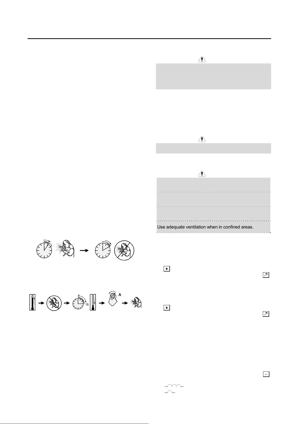
Excessive extension of the duty cycle will cause the
thermal protection circuit to activate.
Minutes or decrease
duty cycle
Input Supply Connection
WARNING
Only a qualified electrician can connect the welding
machine to the supply network. Installation the outlet plug
to power lead and connecting the welding machine had to
be made in accordance with the appropriate National
Electrical Code and local regulations.
Installation and mains outlet socket shall be made and
protected according to appropriate rules. Check the input
voltage, phase, and frequency supplied to this machine
before turning it on. For more information about input
supply refer to the technical specification section of this
manual and to the rating plate of the machine. Verify the
connection of grounding wires from the machine to the
input source.
WARNING
Equipment shall only be used on a supply system that is a
three-phase, four-wire system with an earthed neutral.
Power Source Placement
WARNING
Avoid excessive dust, acid and corrosive materials in the
air.
Keep protected from rain and direct sun when in use
outdoors.
There should be 500 mm space about for the welding
machine to have good ventilation.
Use adequate ventilation when in confined areas.
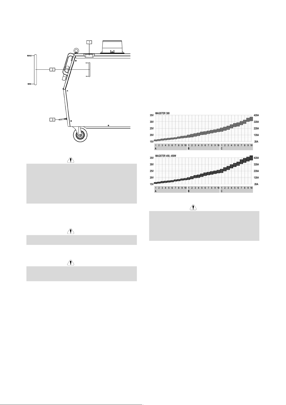
Wire Feeder Connection
To connect the wire feeder to the power source Magster
380 or 450 you should use the combined cable (see
chapter “Accessories”) and do the following:
Connect the combined cable to the socket marked by
.
Connect the control cable to the socket marked by
To connect the wire feeder to the semi power source
Magster 450W you should use the combined cable (see
chapter “Accessories”) and do the following:
Connect the combined cable to the socket marked by
.
Connect the control cable to the socket marked by .
Disconnect the hose, which closes the circuit of the
water cooling system and connect hoses to the
welding source and wire feeder according to colour
marks (the blue hose to the socket with blue
bordering).
Wire diagram of the welding source and wire feeder is
shown in the chapter “Wiring Diagrams”.
Ground Cable Connecting
Connect the ground cable to one of the two sockets ,
additionally marked by:
: high inductance output socket.
: low inductance output socket.