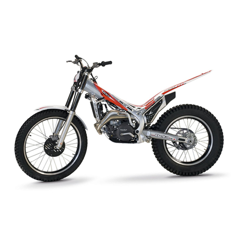
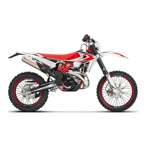
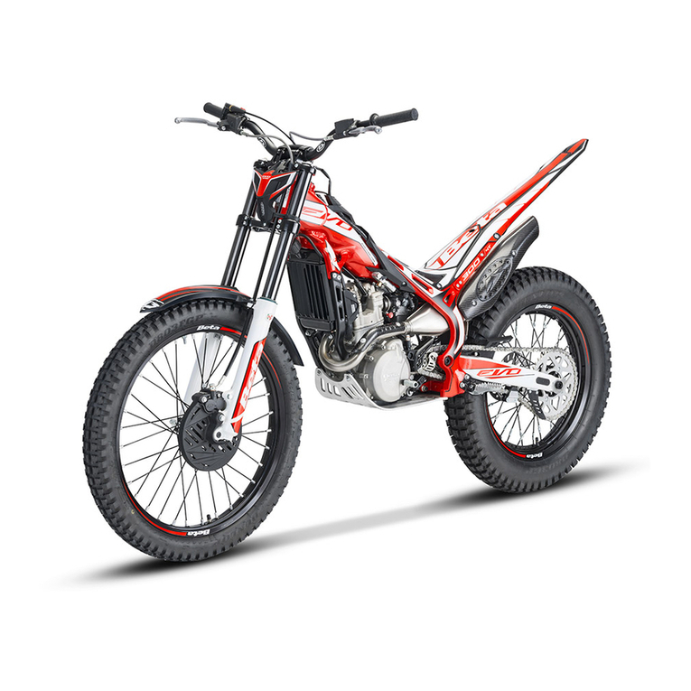
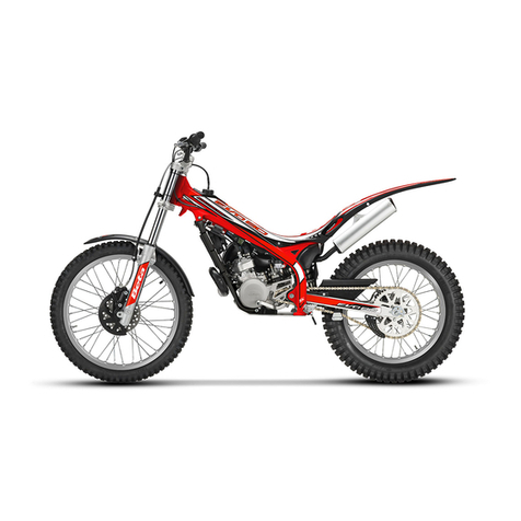
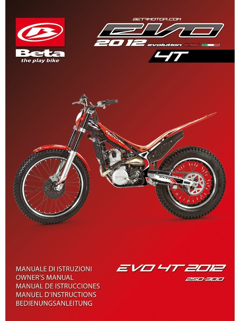
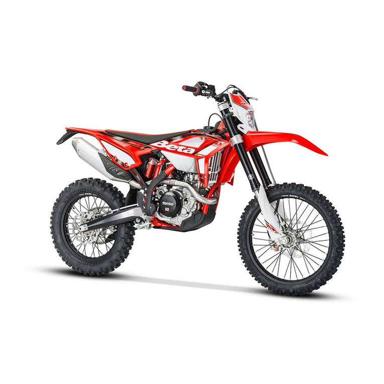
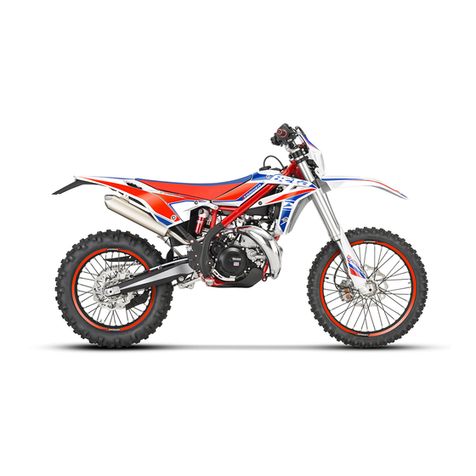
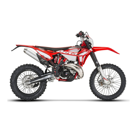
Beta EVO 2T 2010 User manual

MANUALE DI ISTRUZIONI
OWNER’S MANUAL
MANUAL DE ISTRUCCIONES
MANUEL D’INSTRUCTIONS
BEDIENUNGSANLEITUNG
EVO 2T 2010
125 200 250 290cc

39 GB
EVO
Thank you for choosing BETA. Wishing you a lots of good biking!
This manual wiIl give you the information you need to use your
motorcycle correctly and to keep it in excellent condition.
BETAMOTOR S.p.A. reserves the right to change the data and features described in
this manual and to modify its products at any time.

40
GB
AA
AA
ATTENTIONTTENTION
TTENTIONTTENTION
TTENTION
After the first training hour, check all the tightenings and in a particular manner:
•Footboard supports
•Front and rear brake disks
•Wheel rims
•Shock absorber bolt
•Engine bolts and nuts
•Crown

41
INDEX
GB
SECTION 1: GENERAL INFORMATION
Main parts ............................................................................................. 44
Vehicle identification data................................................................................ 44
Instrument panel and controls.......................................................................... 44
Technical data .......................................................................................................... 45
Electrical diagram .................................................................................................... 46
SECTION 2: OPERATION AND USE
Check and maintenance before and after off-road use ............................................... 48
Fueling ........................................................................................................... 48
Recommended lubricants and liquids .............................................................. 49
Breaking in .................................................................................................... 49
Startup - Map switch .......................................................................................... 50
SECTION 3: MAINTENANCE AND CHECKS
Gearbox oil ................................................................................................ 52
Brake pump oil ........................................................................................................ 53
Clutch pump oil ....................................................................................................... 55
Fork oil ................................................................................................................... 56
Air filter ................................................................................................................... 58
Spark plug ............................................................................................................. 59
Generator ............................................................................................................59
Front brake .............................................................................................................. 60
Rear brake ............................................................................................................... 61
Liquid coolant .......................................................................................................... 62
Silencer .................................................................................................................... 62
Carburettor ............................................................................................................... 63
Valve petals ............................................................................................................. 63
Rear shock absorber leverage .......................................................................................64
Checks after cleaning ............................................................................................... 65
Maintenance schedule .............................................................................................. 66
SECTION 4: ADJUSTEMENTS
Adjustement of brake ............................................................................................... 68
Adjustement of clutch ............................................................................................... 68
Adjustement of idling speed ...................................................................................... 69
Adjustement of gas clearance ................................................................................... 69
Adjustement air ..............................................................................................69
Check and adjustement of
steering gear..................................................................... 69
Tightening the chain ................................................................................................. 70
Adjustement of front suspension ................................................................................ 71
Adjustement of rear shock absorber .......................................................................... 72
SECTION 5: WHAT TO DO IN AN EMERGENCY
Troubleshooting ........................................................................................................ 74
ALPHABETICAL INDEX
Index ....................................................................................................................... 75
42

43
GENERAL INFORMATION
GB
1
SECTION
1
INDEXINDEX
INDEXINDEX
INDEX
Main parts
Vehicle identification data
Instrument panel and controls
Technical data
Electrical diagram

44
GENERAL INFORMATION
GB
1
VEHICLE IDENTIFICAVEHICLE IDENTIFICA
VEHICLE IDENTIFICATION DTION D
TION DTION D
TION DAA
AA
ATT
TT
TAA
AA
A
FF
FF
Frame identificationrame identification
rame identificationrame identification
rame identification
Identification data AA
AA
A are stamped on the
right side of the steering gear column.
Motor identificationMotor identification
Motor identification
Motor identification data BB
BB
B are stamped
as indicated in the picture.
INSTRUMENT PINSTRUMENT P
INSTRUMENT PANEL ANDANEL AND
ANEL ANDANEL AND
ANEL AND
CONTROLSCONTROLS
CONTROLSCONTROLS
CONTROLS
11
11
1 Clutch lever
22
22
2 Front brake lever
33
33
3 Throttle grip
MAIN PMAIN P
MAIN PMAIN P
MAIN PARAR
ARAR
ARTSTS
TSTS
TS
1-1-
1-1-
1-Filter box 22
22
2-Fuel tank 3-3-
3-3-
3-Fuel cap
4-4-
4-4-
4-Silencer 5-5-
5-5-
5-Kick starter

45
GENERAL INFORMATION
GB
1

46
GENERAL INFORMATION
GB
1ELECTRICAL DIAGRAM

47 GB
2
OPERATION AND USE
SECTION
2
INDEX
Check and maintenance before and
after off-road use
Fueling
Recommended lubricants and liquids
Breaking in
Start up
Map switch

48
OPERATION AND USE
GB
2CHECKS AND MAINTENANCE BEFORE AND AFTER OFFCHECKS AND MAINTENANCE BEFORE AND AFTER OFF
CHECKS AND MAINTENANCE BEFORE AND AFTER OFFCHECKS AND MAINTENANCE BEFORE AND AFTER OFF
CHECKS AND MAINTENANCE BEFORE AND AFTER OFF-RO-RO
-RO-RO
-ROAD USEAD USE
AD USEAD USE
AD USE
In order to avoid problems connected to the operation of the vehicle, it is advisable
to perform some checking and maintenance operations before and after use. Just a
few minutes given to these procedures will save you time and money, and wilI make
riding much safer. Proceed as follows:
TYRES check pressure, general condition and thickness of tread
SPOKES check for correct tension
NUTS AND BOLTS check completely all bolts and nuts
CHAIN check tension (20 mm play) and grease if necessary
AIR FILTER clean filter and wet with suitable oil for filters
Note:Note:
Note:Note:
Note:
Check that you have the vehicle identification documents.
On cold days, warm up the motor by running it at minimum for a few instants before
starting off..
..
. Wash the vehicle carefully after every off-road use.
FUELINGFUELING
FUELINGFUELING
FUELING
Remove cap AA
AA
A.
The fuel tank holds approximatelyThe fuel tank holds approximately
The fuel tank holds approximately
2,6 liters, 0,5 liter of which is re-2,6 liters, 0,5 liter of which is re-
2,6 liters, 0,5 liter of which is re-
serve.serve.
serve.serve.
serve.
Use only a mixture of unleaded super fuel
and oil (mineral oil 4%, synthetic oil 1,5
%)

49 GB
2
OPERATION AND USE
RECOMMENDED LUBRICANTS AND LIQUIDS
For better operation and longer vehicle life, we advise you to use the products listed
in the following chart:
TYPE OF PRODUCT TECHNICAL SPECIFICATION
MOTOR OIL
OIL FOR MIXTURE
BRAKE AND CLUTCH OIL
BARDAHL VBA KXT
BARDAHL BRAKE FLUID DOT 4
BARDAHL OUTBOARD GREASE
BARDAHL PERMANENT
IDEMITSU OJ-RACING-01
or
BEL RAY "MC 10 SAE 5"
FORK OIL
GREASE FOR JOINTS AND RODS
LIQUID COOLANT
BARDAHL GEARBOX 10W30
BREAKING IN
Breaking in takes approximately 10 hours of operation.
During this time we suggest to:
•Ride after having well warmed the engine
•Avoid travel at constant speed
•Change speed often so that the parts wiII break in uniformly and in a shorter time
•Avoid turning the throttle more than 3/4 of the way.
Warning:
•After the first 5 hours of operation, change the gear box oil.
•Always use a mixture of unleaded super fuel and oil (mineral oiI 4%,
synthetic oil 1,5 %).
•After the first off-road use, check all the nuts and bolts.
NOTE:
For substitution, follow attentively the chart.

50
OPERATION AND USE
GB
2STARTUP
MAP SWITCH
•Open fuel tank valve B
OFF = closed
ON = open
RES = reserve
•Check that the gears are in neutral.
•Depress the kick-starter with a sharp
movement the foot and slightly turn the
gas control.
•Always close the fuel tank valve when
the engine is off.
Note:
When the engine is cold, use choke A.
Pull the lever, wait a few seconds, and
then return the lever to its starting position.
OFF
ON
RES
Attention!
During competition use or extreme “trial
zone” is advising to position the fuel tap
on “RES” to guarantee an optimal fuel
supply in all condition use.
1
2
Using the switch shown in the picture, it
is possible to choose between two
different map for spark advance.
With the switch in position 1, “soft”
map is selected, more suitable for
slippery terrain and for a softer engine
response.
With the switch in position 2 , “hard”
map in selected, for a more aggressive
engine response: more suitable for dry
condition.

51 GB
3
MAINTENANCE AND CHECKS
SECTION
3
INDEXINDEX
INDEXINDEX
INDEX
Gearbox oil
Brake pump oil
Clutch pump oil
Fork oil
Air filter
Spark plug
Generator
Front brake
Rear brake
Cooling liquid
Silencer
Carburettor
Valve petals
Rear shock absorber Leverage
Checks after cleaning
Maintenance schedule

52
MAINTENANCE AND CHECKS
GB
3GEARBOX OILGEARBOX OIL
GEARBOX OILGEARBOX OIL
GEARBOX OIL
CheckCheck
CheckCheck
Check
Hold the vehicle vertical to the ground.
When engine is cold check the oil level by
means of porthole AA
AA
A. The oil level must
be always visible from the porthole.
In contrary case restore the oil level through
cap BB
BB
B.
Oil changeOil change
Oil change
The engine must be hot when changing
oil:
•Place a container under the engine
•Unscrew the filler cap and oiI drain plug
CC
CC
C
•Empty the crankcase completely
•Close drain plug CC
CC
C
•Put in the right oil quantity (table on page
45)
•Close the filler cap.
Note:Note:
Note:Note:
Note:
Change the gearbox oil after the first 5
hours of operation. For all subsequent
changes, follow the instructions given on
the chart on pag. 66, using the Iubricants
recommended on pag. 49.

53 GB
3
MAINTENANCE AND CHECKS
BRAKE PUMP OILBRAKE PUMP OIL
BRAKE PUMP OIL
FF
FF
Front brakeront brake
ront brakeront brake
ront brake
Check the oil level by means of oiI port-
hole AA
AA
A. The oil level must be always vis-
ible from the porthole. In contrary case re-
store the oil level.
To restore the oil level, top up by unscrew-
ing the two screws B,B,
B,B,
B, lifting cap CC
CC
C and
adding oil.
WW
WW
Warning:arning:
arning:arning:
arning:
lf you feel the lever too soft, there may be
an air bubble in the circuit. Apply to your
dealer immediately.
Note:Note:
Note:Note:
Note:
For oil changes, follow the instructions
given on the chart on pag. 66, using the
Iubricants recommended on pag. 49.
Rear brakeRear brake
Rear brake
To check the oil level remove the rear
cover by unscrewing its 5 relevant screws ,
then check oil level by means of oil con-
tainer EE
EE
E.
Oil level must never be below the minimum
level mark on container EE
EE
E. To restore the
oil level, top up by means of oil filler cap.

54
MAINTENANCE AND CHECKS
GB
3Bleeding of front brakeBleeding of front brake
Bleeding of front brakeBleeding of front brake
Bleeding of front brake
To bleed air from the front brake circuit,
proceed as follows:
•Remove the rubber cap AA
AA
A from valve BB
BB
B
•Open the oiI sump cap
•Insert one end of a trasparent tube into
valve BB
BB
B and the other end into a con-
tainer
•Pump with the brake lever 2/3 times and
keep the lever pressed
•Unscrew the valve and let the oil drain
•Close the valve and release the lever
•If air bubbles are still visible in the tube
repeat above operation until obtaining a
continuous outflow of oil with no air bub-
bles
Note:Note:
Note:Note:
Note: During this procedure, continu-
ously top up the brake pump tank to re-
place the oil that is out flowing
•Remove the tube.
•Replace the rubber cap.
Note:Note:
Note:Note:
Note:
Handle the hydraulic oiI very carefully. It
is corrosive, and will irreparably dam-
age painted or plastic parts of the mo-
torcycle upon contact.
Bleeding of rear brakeBleeding of rear brake
Bleeding of rear brake
To bleed air from the rear brake circuit,
proceed as follows:
•Remove the rubber cap CC
CC
C from valve DD
DD
D
•Open the oiI sump cap
•Insert one end of a trasparent tube into
valve DD
DD
D and the other end into a con-
tainer
•Pump with the brake lever 2/3 times and
keep the lever pressed
•Unscrew the valve and let the oil drain
•Close the valve and release the lever
•If air bubbles are still visible in the tube
repeat above operation until obtaining a
continuous outflow of oil with no air bub-
bles
Note:Note:
Note:Note:
Note: During this procedure, continu-
ously top up the brake pump tank to re-
place the oil that is out flowing
•Remove the tube.
•Replace the rubber cap.

55 GB
3
MAINTENANCE AND CHECKS
CLUTCH PUMP OILCLUTCH PUMP OIL
CLUTCH PUMP OIL
Check the oil level. The oil level must never
be below half the tank capacity.
To restore the oil level, top up by unscrewing
the two screws AA
AA
A, lifting cop BB
BB
B and adding
oil.
Note:Note:
Note:Note:
Note:
For oiI changes, follow the instructions
given on the chart on pag. 66, using the
Iubricants recommended on pag. 49
Note:Note:
Note:Note:
Note:
Handle the hydraulic oiI very carefully. It
is corrosive, and will irreparably damage
painted or plastic parts of the motorcycle
upon contact.
Bleeding of clutchBleeding of clutch
Bleeding of clutch
To bleed air from the clutch circuit, pro-
ceed as follows:
•Remove the rubber cap CC
CC
C from valve DD
DD
D
•Open the oiI sump cap
•Insert one end of a trasparent tube into
valve DD
DD
D and the other end into a con-
tainer
•Pump with the cluth lever 2/3 times and
keep the lever pressed
•Unscrew the valve and let the oil drain
•Close the valve and release the lever
•If air bubbles are still visible in the tube
repeat above operation until obtaining a
continuous outflow of oil with no air bub-
bles
Note:Note:
Note:Note:
Note: During this procedure, continu-
ously top up the clutch pump tank to re-
place the oil that is out flowing
•Remove the tube
•Replace the rubber cap.

56
MAINTENANCE AND CHECKS
GB
3FORK OILFORK OIL
FORK OILFORK OIL
FORK OIL
Right shaftRight shaft
Right shaft
To replace the oil, proceed as follows:
1) Remove the front wheel
2) Remove the handlebar (see pag.69)
3) Loosen left shaft lock screws AA
AA
A and
take off the slider
4) Unscrew upper plug BB
BB
B
5) Unscrew fixing lock nut and take off
the plug
6) Unscrew the fixing screw of the
cartridge positioned under the slider,
and extract the cartridge
7) Empty the fork leg and the cartridge,
draining all the oil inside
8) Reassemble the cartridge on the slider
tightening the fixing screw, then refill
oil (OJ01) in the cartridge up to the
level indicated in the figure (with fork
in the fully compressed position)
9) Reassemble the plug on the rod, tighten
the lock nut and, extending the fork
leg, screw the plug on the shaft
10) Reassemble the fork
60 mm
Oil
level
Note:Note:
Note:Note:
Note:
For screw A: torque wrench setting
7,8 : 9,1 Nm.

57 GB
3
MAINTENANCE AND CHECKS
Left shaftLeft shaft
Left shaft
To replace the oil, proceed as follows:
1) Remove the front wheel
2) Remove the handlebar (see pag. 69)
3) Loosen the shaft lock screws AA
AA
A
4) Unscrew slider plug BB
BB
B
5) Remove the spring and totally empty
the oil
6) Fill oil up to the level indicated in
figure (with fork compressed in the fully
compressed posistion)
7) Reassemble the spring and extend fork
leg
8) Screw the plug B
Note:Note:
Note:Note:
Note:
For all changes, follow the instructions
given on the chart on pag. 66, using the
Iubricants recommended on pag. 49.
Check regularly and clean thoroughly
removing any dirt on dust cover and also
check the rubber seal to ensure a good
seal.
Note:Note:
Note:Note:
Note:
For screw A: torque wrench setting
7,8 : 9,1 Nm.
Oil
level
120 mm
This manual suits for next models
8
Table of contents
Other Beta Motorcycle manuals

Beta
Beta RR 525 User manual

Beta
Beta EVO 4T User manual

Beta
Beta RR 250 2T EUROPA 2019 User manual

Beta
Beta ALP 200 User manual

Beta
Beta RR 4T ENDURO 2014 350 User manual

Beta
Beta 125 RR-S 2020 User manual

Beta
Beta X-Trainer 300 2T User manual

Beta
Beta EVO 4T 2012 User manual

Beta
Beta Evo 2T 2011 User manual

Beta
Beta RR 4T-400 Instruction manual