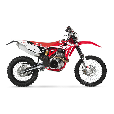
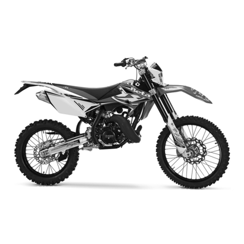
Beta Motard M4 User manual

Motard M4
Service Manual
Holtvej 8-10, Høruphav, 6470 Sydals
Telefon: +45 73 15 11 00
Fax: +45 73 15 11 01
CVR: 27 73 31 07
www.betamotor.dk
Juli 2011

81 GB
ALP 4.0 - MOTARD M4
Thanks for you preference, and have a good time! This hand-
book contains the information you need to properly operate and
maintain your motorcycle.
The data and specifications provided in this manual does not constitute an
engagement on the part of BETAMOTOR S.p.A. BETAMOTOR reserves the
right to make any changes and improvements to its models at any moment
and without notice.

82
GB
IMPORTANT
We recommend you to check all the tightenings after the first one
or two hours’ ride over rough ground. Special attention should
be paid to the following parts:
•rear sprocket
•footrest supports
•front / rear brake caliper
•mudguard bracket
•engine bolts
•shock absorber bolts
•wheel spokes
•rear frame
•oil tank joints on frame
IMPORTANT
For any servicing requirements, please get in contact with
Betamotor’s authorized service network.

CONTENTS
83 GB
Operating instructions .......................................................................... 85
Ecologic guide .................................................................................... 85
Riding safety ...................................................................................... 86
CHAPTER 1 GENERAL INFORMATION .......................................... 87
Vehicle identification data ..................................................................... 88
Delivery ............................................................................................ 88
Load ................................................................................................. 89
Tyres ................................................................................................. 89
Familiarizing with your vehicle ............................................................... 91
Keys and locks ................................................................................... 92
Ignition switch / Steering lock ............................................................... 92
Helmet lock........................................................................................ 92
Instrument panel and controls................................................................. 93
LCD................................................................................................... 94
Specifications ................................................................................... 102
Wiring diagrams .............................................................................. 106
Electrical devices .............................................................................. 108
CHAPTER 2 OPERATION .............................................................. 111
Checks and maintenance operations before and after off-road use ............. 112
Recommended lubricants .................................................................... 112
Running-in ........................................................................................ 113
Starting the engine ............................................................................ 114
Shutting off the engine ....................................................................... 115
Refuelling......................................................................................... 116
CHAPTER 3 CHECKS AND MAINTENANCE ................................. 117
Motor oil level check .......................................................................... 118
Motor oil and oil filter substitution .......................................................... 120
Fume collecting tube .......................................................................... 124
Brake pump oil - Bleeding the brakes .................................................... 124
Fork oil............................................................................................ 128
Air filter ........................................................................................... 129
Spark plug ....................................................................................... 130
Brakes ............................................................................................ 131
Carburetor ....................................................................................... 132
Battery ............................................................................................ 132
Removing the plastics ......................................................................... 133
Notes for cross-country ........................................................................ 137
Final transmission group substitution ....................................................... 138
Cleaning and checking the vehicle ....................................................... 140
Checks after cleaning ......................................................................... 140
CONTENTS
84
GB
Scheduled maintenance ..................................................................... 141
Prolonged inactivity ........................................................................... 142
After prolonged inactivity ..................................................................... 142
CHAPTER 4 ADJUSTMENTS ......................................................... 143
Adjusting the brakes .......................................................................... 144
Adjusting the clutch............................................................................ 144
Rear shock absorber regulation ............................................................. 145
Adjusting the slow running .................................................................. 145
Adjusting the throttle play .................................................................... 145
Checking and adjusting the steering play .............................................. 146
Tensioning the chain .......................................................................... 147
Adjusting the headlight ....................................................................... 148
CHAPTER 5 REPLACEMENTS ........................................................ 149
Replacing the front brake pads ............................................................. 150
Replacing the rear brake pads .............................................................. 152
Replacing the bulbs ALP ...................................................................... 153
Replacing the bulbs MOTARD............................................................... 154
Replacing the turn indicator bulbs ......................................................... 155
CHAPTER 6 TROUBLESHOOTING ................................................ 157
INDEX ........................................................................................... 159

85 GB
OPERATING INSTRUCTIONS
•The vehicle must be accompanied by: number-plate, registration document, tax
disc and insurance.
•Do not carry any animals or objects which are not securely fastened to the vehicle,
or exceed the vehicle’s overall dimensions or the maximum load specified by the
manufacturer.
•Riding without a crash helmet is forbidden.
•Any modifications of the engine or other parts resulting in a power and/or speed
increase are punishable by severe sanctions including the confiscation of the vehi-
cle.
•To protect your safety and that of others, always wear a crash helmet and adopt a
safe riding conduct.
WARNING
Any modifications and tampering with the vehicle during the warranty period
exempt the manufacturer from all responsibility and invalidate warranty.
ECOLOGIC GUIDE
•Each vehicle powered by an internal combustion engine produces varying quanti-
ties of acoustic and atmospheric pollution based on the riding style adopted.
•The abatement of noise and air pollution levels is the duty of everybody. Avoid full-
throttle starts, sudden acceleration and abrupt braking. This will reduce noise emis-
sion as well as the wear and tear of the tyres and mechanical parts, and will also
allow a considerable reduction in fuel consumption.

86
GB
RIDING SAFETY
•Observe the Highway Code.
•Always put on and fasten a homologated helmet.
•Always keep the crash helmet visor clean.
•Avoid wearing garments with hanging ends.
•Do not keep sharp or brittle objects in your pockets while riding.
•Be sure to adjust in the right way the rearview mirrors.
•Always ride in a seated position, with both hands on the handlebars and both feet
on the footrests.
•Always pay attention and do not allow anything to distract you while riding.
•Do not eat, drink, smoke, use a mobile phone, etc. while riding.
•Do not wear headphones to listen to music while riding.
•Never ride abreast with other vehicles.
•Do not tow and avoid being towed by other vehicles.
•Always keep a safe distance from other vehicles.
•Do not sit on the vehicle when it is on its stand.
•Do not start off while the vehicle is on its stand.
•Do not pull out the stand when the vehicle is facing downhill.
•Avoid swaying and wheelies as they are extremely dangerous for your own and
other people’s safety as well as for your vehicle.
•Always apply both brakes on dry roads with no gravel and sand. Using one brake
may be dangerous and cause uncontrolled skidding.
•To reduce the braking distance, always apply both brakes.
•On wet roads, ride at moderate speed and be very careful, especially when
applying the brakes.
•Do not start the engine in closed places.

1
GENERAL INFORMATION
87 GB
CONTENTS
CHAPTER 1 GENERAL INFORMATION
Vehicle identification data
Delivery
Load
Tyres
Familiarizing with your vehicle
Keys and locks
Ignition switch / Steering lock
Crash helmet lock
Instrument panel and controls
LCD
Specifications
Wiring diagram
Electrical devices

1
GENERAL INFORMATION
88
GB
VEHICLE IDENTIFICATION DATA
Frame identification data A are stamped
on the right side of the steering head tube.
FRAME IDENTIFICATION
Engine identification data B are stamped
in the area shown in the figure.
WARNING:
Tampering with the identification numbers
is severely punished by law.
ENGINE IDENTIFICATION
DELIVERY
•The vehicle is supplied ready for use. However, it is advisable to conduct a few
simple checks before riding:
- Check the tyre pressures (when first
refuelling).
- Check the oil level in the engine.
•The following items are supplied as
standard and are contained in a plas-
tic envelope placed in a compartment
under the saddle: operation and main-
tenance manual, tool kit (ignition span-
ner, double-function screwdriver).
A
B

1
GENERAL INFORMATION
89 GB
LOAD
•Maximum load (rider + passenger + load): 340 kg.

•To avoid to let the vehicle be unstable, do not carry bulky or heavy objects.
•Do not carry objects that stick from the vehicle or cover the lighting and signalling
devices.
TYRES
WARNING:
For your riding safety, frequently check the
tyres.
•Keep the tyre pressures within the pre-
scribed range.
•Check the tyre pressures every other
week.
•Always measure the inflating pressures
when the tyres are cold.
pressure is too low
pressure is correct
pressure is too high
TYRES ALP 4.0
TYRE
Size
Pressure kg/cm2
REAR
(140/80-18) 70R
or (130/80-18) 66R
1,8
FRONT
(90/90-21)
54R
1,5
TYRES MOTARD M4
TYRE
Size
Pressure kg/cm2
REAR
(150/60-17)
66R
2,2
FRONT
(120/70-17)
54R
2,0

1
GENERAL INFORMATION
90
GB
Note:
The tyre (TUBE TYPE) tread depth must never be less than 2 mm.
Failure to comply with this rule is punished under the regulations in force.
•Before riding, check the tyres for cuts, cracks, abrasions, bulges, etc. If any defects
are found, have the tyres checked by an expert as riding with a damaged tyre can
be extremely dangerous.
•If a tyre gets punctured, stop the vehicle immediately. Riding with a flat tyre is
dangerous and may seriously damage the tyre itself and the wheel rim.

1
GENERAL INFORMATION
91 GB
FAMILIARIZING WITH THE VEHICLE
Main parts:
1- Air filter
2- Fuel tank
3- Tank cap
4- Silencer
5- Rear shock
absorber
6- Headlight
7- Front turn
indicators
8- Rear light
9- Rear turn indicators
10- Side stand
11- Crash helmet lock
12- Rearview mirrors
13- Passenger’s
footrests
14- Fork
15- Rider’s footrests
16- Undercowl
17- Saddle
18- Engine
19- Front mudguard
20- Number-plate
holder
21- Kick-start (optio-
nal)
20
17
12 18
19
14
16
21
13
15
7
10
6
5
3
2
1
8
9
4
11
ALP 4.0
MOTARD M4

1
GENERAL INFORMATION
92
GB
KEYS AND LOCKS
The vehicle is supplied with two keys and the related spares for the ignition switch/
steering lock and the crash helmet lock.
WARNING
Do not keep the spare keys in the vehicle. Keep the keys in a safe and easy-to-reach
place. The code number stamped on the keys should be copied on this manual (or
elsewhere) so it can be used to ask for duplicates should both keys be lost.
OFF: Electrical equipment disabled.
ON: The vehicle can be started.
LOCK: Steering lock on.
To lock the handlebar, turn it to
the left, press the key, rotate it
anticlockwise all the way and
then release it.
CRASH HELMET LOCK
Insert the key into the lock located on the left side under the saddle, and then rotate
it anticlockwise to open the crash helmet hook.
IGNITION SWITCH/STEERING LOCK
It controls the ignition circuit and the steering lock.
ON
OFF
LOCK

1
GENERAL INFORMATION
93 GB
1- LCD
2- Ignition switch
3- Neutral warning light
4- Turn indicator warning light
5- High beam warning light
6- Stand warning light
7- Clutch lever
8- Front brake lever
9- Throttle twist grip
10- Engine start button
11- Engine stop button
12- Turn indicator switch
13- Horn button
14- Lights selector switch
15- High beam flash switch
16- Scroll
17- MODE button
INSTRUMENT PANEL AND CONTROLS
1
2
3
4
5
6
78
9
10
11
12
13
14 15
17
16

1
GENERAL INFORMATION
94
GB
LCD DISPLAY
Operation and display of pages and icons
1ISTANT SPEED
2ODO – TOTAL COUNTER
3TRP – TRIP COUNTEER
4AVS – TRP AVERAGE SPEED
5LAP – STOPWATCH (FORMATS HH:MM )
6CLK – CLOCK FORMATS hh:mm:ss, con 12h e 24h, e mm:ss
7TACHOMETER BARS
8SPEED max – MAXIMUM SPEED
9 ICON BATTEERY
10 ICON HOURS TO OIL CHENGE
11 ICON FUEL
12 ICON SERVICESPANNER
13 ICON TEMPERATURE WATER (NOT ACTIVE)
14 BATTERY RECHARGING BAR
12
10 613
5
4
3
8
1
1114 9
2
7

1
GENERAL INFORMATION
95 GB
Order of pages on LCD display
The different pages can only be viewed in succession starting from the default page.
Turn the ignition switch to the ON posi-
tion. General check of all the icons and
bars on the LCD display and warning light
test.
The test lasts 3 seconds.
At the end of the test the default page is
displayed.
The default page is automatically displayed
at the end of the test.
Displayed information:
Battery - Shows the battery charge on a
vertical bar (min. 10.4 V, max. 14.5 V).
Instant speed at the top (max. 199
km/h or Mph).
ODO - Total counter measuring the kilo-
metres or miles covered from the initial set-
up. It is displayed at the bottom (max. read-
ing 999,999 kilometres or miles). The
parameter cannot be reset
Page 1 - TEST
Page 2 - DEFAULT PAGE

1
GENERAL INFORMATION
96
GB
Page 3 - TRP
Page 4 - AVS
Page 5 - LAP
- Stopwatch hours:minutes:seconds
While page 2 is displayed, briefly press
MODE if the vehicle is stationary or
SCROLL while travelling to bring up page
3.
The new page is displayed as soon as the
button is released.
Displays:
Instant speed at the top (max. 199
km/h or Mph)
TRP Trip counter, displayed at the bot-
tom (max. 999.9 km or miles)
The counter can be reset manually (see
page 99) or automatically when 999.9
km or miles are totalled.
While page 3 is displayed, briefly press
MODE if the vehicle is stationary or
SCROLL while travelling to bring up page
4.
The new page is displayed as soon as the
button is released.
Displayed information:
Instant speed at the top (max. 199
km/h or Mph)
AVS Actual average speed for TRP
(calculated only while travelling) at the
bottom.
The parameter cannot be reset manually.
It is only reset at the same time as the TRP
page.
While page 4 is displayed, briefly press
MODE if the vehicle is stationary or SCROLL
while travelling to bring up page 5.
The new page is displayed as soon as the
button is released.
Displayed information:
Instant speed at the top (max. 199 km/
h or Mph). It displays:
HOURS:MINUTES:SECONDS 00:00:00
at the bottom.
Operation:
The controls operate only when
page 5 or 6 are displayed.
- Manual start/stop obtained by briefly press-
ing the SCROLL button.
- Automatic start/stop from wheel pulse. Three
seconds after the wheel has come to a halt,
the stopwatch ceases to operate and the
delay is compensated for.

1
GENERAL INFORMATION
97 GB
Page 6 - LAP – Stopwatch
minutes:seconds:tenths of a second
Page 7 - CLK - Clock
hours:minutes:seconds
Pressing SCROLL for 1.5 seconds while page
5 is displayed brings up figure 21 for 1 sec-
ond with the bars
- - : - - :- - at the top.
Holding down SCROLL brings up page 5
again.
Releasing the SCROLL button brings up page
6.
Displayed information:
Stopwatch format
MINUTES:SECONDS 00:00
displayed at the top. Two small digits are used
for tenths of a second. It works exactly as page
5, of which it represents an extension.
When this page is reset, page 5 is also reset
and vice versa.
Instant speed on small digits (max. 199
km/h or Mph)
Pressing SCROLL for 1.5 seconds while
page 6 is displayed, brings up figure 21
for 1 second.
Holding down SCROLL brings up page 6
again.
Releasing the SCROLL button brings up page 7.
Displayed information:
Instant speed at the top (max. 199 km/h
or Mph)
Clock HOURS:MINUTES:SECONDS
at the bottom, 00:00:00.
The parameter can be adjusted by pressing
MODE or SCROLL while the vehicle is station-
ary.
If Km/h has been selected, the clock will oper-
ate in 24-hour format. 23:59:59
If Mph has been selected, the clock will operate
in 12-hour format. 11:59:59 with AM/
PM added automatically when Mph is select-
ed.
Clock setting procedure
1. Press the MODE or SCROLL button until the hour digits start blinking.
2. Releasing the button and then pressing it again. increases the hours by one unit.
Holding down the button causes the figures to change rapidly. Leaving the button
inactive skips to step 4.
3. Release the button when the correct hour setting has been obtained.
4. After 2 seconds the minute digits start blinking.
5. Use the procedure described at step 2. Leaving the button inactive skips to step 8.
6. Release the button when the correct minute setting has been obtained.
7. After 2 seconds the second digits start blinking.
8. Use the procedure described at step 2.
9. Release the button when the correct second setting has been obtained. The new time
setting is stored after 2 seconds.
10. Changing the speed unit from Km/h to Mph causes the time display to change
from the 24-hour to the 12-hour format.

1
GENERAL INFORMATION
98
GB
Page 8 - CLK - Clock minutes:seconds
Page 10 - SPEED max
While page 7 is displayed, briefly press
MODE if the vehicle is stationary or SCROLL
while travelling to bring up page 8.
The new page is displayed as soon as the
button is released.
Displayed information:
Clock format
MINUTES:SECONDS 00:00
at the top. The parameter can only be adjust-
ed by pressing MODE or SCROLL while min-
utes or seconds are selected and the vehicle
is stationary.
It also updates page 7, of which it represents
an extension.
Instant speed at the top (max. 199 km/
h or Mph).
While page 8 is displayed, briefly press
MODE if the vehicle is stationary or
SCROLL while travelling to bring up page
9.
The new page is displayed as soon as the
button is released.
Displayed information:
Instant speed at the top (max. 199
km/h or Mph)
SPEED max Maximum speed reached
from the last time the parameter was reset.
It can be reset manually.
Blanking out pages
If a page is of no interest to the user, it can be blanked out while remaining active to
speed up the display of the next page.
All the pages can be blanked out, individually or in sets, with the exception of default
page 2.
To blank out a page:
While the page is displayed, press MODE or
SCROLL and hold it down until WS appears
in the bottom right corner of the LCD display.
When the button is released, the page will no
longer be visible.
To display all blanked out pages again:
While the default page is displayed, press
MODE or SCROLL and hold it down until
WS appears in the bottom right corner of the
LCD display.
If no page had been previously blanked out, all
pages will be blanked out.
To display the pages again, repeat the above
procedure.

1
GENERAL INFORMATION
99 GB
Resetting the TRP, SPEED max and LAP parameters.
The following parameters can be reset:
- TRP, trip counter, and consequently AVS.
- SPEED max, maximum speed reached by the vehicle.
Times indicated by LAP in both configurations while either of the two pages is displayed.
The parameters can be reset by pressing the MODE button while the vehicle is stationary
or the SCROLL button at all time.
Resetting the TRP and SPEED max parameters
Press MODE or SCROLL for at least 5 sec-
onds, causing 0.0 to be displayed in place
of the figure.
The TRP parameter can only be reset while
the vehicle is stationary. Resetting TRP also
causes AVS to be reset.
Resetting the LAP parameter
When the LAP time is reset, pages 5 and
6, which are strictly dependent on it, are
also reset.
The figures will be replaced by the hori-
zontal bars, which will remain visible for 1
second.
Releasing the MODE or SCROLL button
while the bars are displayed resets the fi-
gure.
Holding down the MODE or SCROLL but-
ton brings up the next page while retai-
ning the figures on the current page.
This manual suits for next models
1
Table of contents
Other Beta Motorcycle manuals

Beta
Beta RR 4T-400 Instruction manual

Beta
Beta Evo 2T 2011 User manual

Beta
Beta Rev 4T User manual

Beta
Beta RE 125 User manual

Beta
Beta RR 400 User manual

Beta
Beta EVO 2T User manual

Beta
Beta 2009 Evo 2T 125 User manual

Beta
Beta RR4T USA 400 User manual

Beta
Beta RR 50 cc ENDURO User manual

Beta
Beta RR 4T ENDURO 2014 350 User manual

Beta
Beta RR 50 CC ENDURO User manual

Beta
Beta Rev 4T User manual

Beta
Beta RR 125 series User manual

Beta
Beta minitrial-e User manual

Beta
Beta 400 RS 2014 User manual

Beta
Beta 2008 URBAN 125cc User manual

Beta
Beta RR 50 CC series User manual

Beta
Beta Ark AC User manual

Beta
Beta 350-498 RR User guide

Beta
Beta RR 125 cc User manual