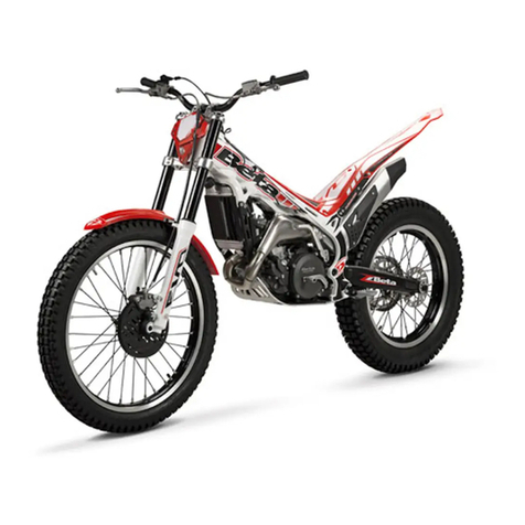
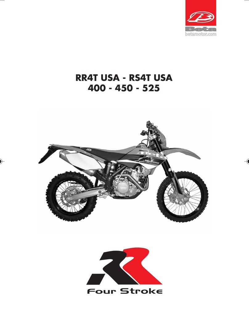
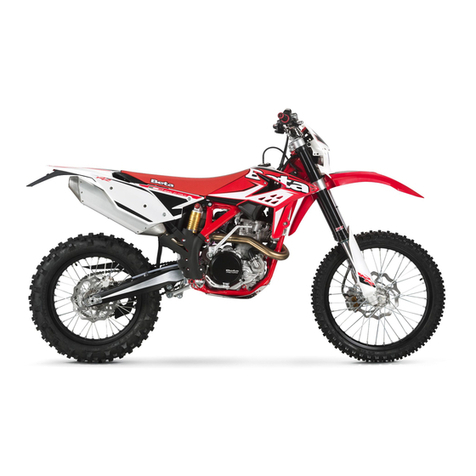
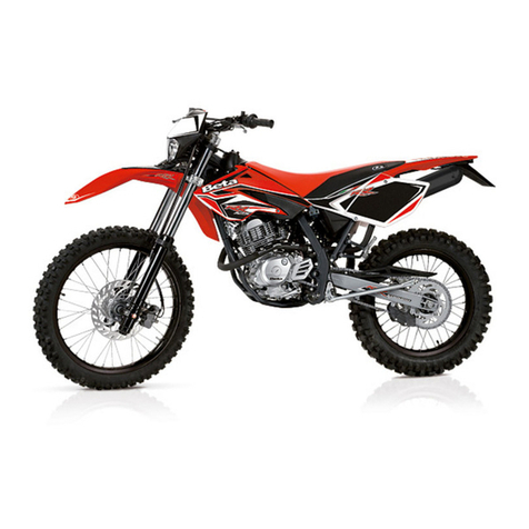
Beta RR 525 User manual

77 GB
RR 250 - 400 - 450 - 525
Thanks for you preference, and have a good time! This hand-
book contains the information you need to properly operate and
maintain your motorcycle.
The data and specifications provided in this manual does not constitute an
engagement on the part of BETAMOTOR S.p.A. BETAMOTOR reserves the
right to make any changes and improvements to its models at any moment
and without notice.

78
GB
IMPORTANT
We recommend you to check all the tightenings after the first one
or two hours’ ride over rough ground. Special attention should
be paid to the following parts:
•rear sprocket
•ensure that the footrests are properly fixed
•front/rear brake levers/calipers/discs
•check that the plastics are properly fastened
•engine bolts
•shock absorber bolts/swingarm
•wheel hubs/spokes
•rear frame
•pipe connections
•tensioning the chain
IMPORTANT
For any servicing requirements, please get in contact with
Betamotor’s authorized service network.

CONTENTS
79 GB
Operating instructions ........................................................................... 81
Ecologic guide .................................................................................... 81
Riding safety ....................................................................................... 82
CHAPTER 1 GENERAL INFORMATION ....................................... 83
Vehicle identification data ...................................................................... 84
Delivery ............................................................................................. 84
Load .................................................................................................. 85
Tyres .................................................................................................. 85
Steering lock ....................................................................................... 86
Familiarizing with your vehicle ................................................................ 87
Controls ............................................................................................. 88
Specifications ...................................................................................... 94
Wiring diagrams ................................................................................. 98
Electrical devices ............................................................................... 100
CHAPTER 2 OPERATION ......................................................... 103
Checks to be performed before each ride ............................................... 104
Recommended lubricants ..................................................................... 105
Running-in ......................................................................................... 105
Starting the engine ............................................................................. 106
Refuelling.......................................................................................... 108
CHAPTER 3 CHECKS AND MAINTENANCE ............................... 109
Motor oil level check .......................................................................... 110
Motor oil and oil filter substitution .......................................................... 111
Check the level of the front and rear brake fluid and bleeding .................... 114
Check the front and rear brake pads ..................................................... 116
Check the oil level in the hydraulic clutch and bleeding ............................. 117
Fork oil............................................................................................. 118
Air filter ............................................................................................ 119
Spark plug ........................................................................................ 120
Carburetor ........................................................................................ 121
Coolant............................................................................................ 124
Removing the plastics .......................................................................... 125
Drive chain maintenance and wear ....................................................... 129
Suspensions: telescopic fork and shock absorber...................................... 130
Charging the battery .......................................................................... 132
Cleaning and checking the vehicle ........................................................ 133
Scheduled maintenance ...................................................................... 134
Prolonged inactivity ............................................................................ 135

CONTENTS
80
GB
CHAPTER 4 ADJUSTMENTS..................................................... 137
Brake adjustment: front lever and brake pedal ......................................... 138
Adjusting the decompressor lever control cable ........................................ 138
Adjusting the home position of the clutch lever ......................................... 139
Adjusting the handlebars ..................................................................... 139
Adjusting the throttle control cable ......................................................... 140
Checking and adjusting the steering play ............................................... 140
Tensioning the chain ........................................................................... 141
Adjusting the headlight ........................................................................ 142
CHAPTER 5 REPLACEMENTS ................................................... 143
Replacing the brake pads: front and rear ................................................ 144
Replacing the headlight bulbs ............................................................... 146
Replacing the rear light bulb................................................................. 146
Replacing the exhaust-pipe................................................................... 147
CHAPTER 6 TROUBLESHOOTING ............................................ 149
INDEX................................................................................... 151

81 GB
OPERATING INSTRUCTIONS
•The vehicle must be accompanied by: number-plate, registration document, tax
disc and insurance.
•Do not carry animals, pets or loose objects that can stick out from the vehicle.
•Riding without a crash helmet is forbidden.
•Always ride with the low beam on.
•Any modifications of the engine or other parts resulting in a power and/or speed
increase are punishable by severe sanctions including the confiscation of the vehi-
cle.
•To protect your safety and that of others, always drive carefully and with your
helmet on.
WARNING
Any modifications and tampering with the vehicle during the warranty period ex-
empt the manufacturer from all responsibility and invalidate warranty.
ECOLOGIC GUIDE
•Every vehicle powered by an internal combustion engine produces an amount of
noise (noise pollution) and gases (air pollution) which varies with the riding style.
•The abatement of noise and air pollution levels is the duty of everybody. Avoid full-
throttle starts, sudden acceleration and abrupt braking. This will reduce noise emis-
sion as well as the wear and tear of the tyres and mechanical parts, and will also
allow a considerable reduction in fuel consumption.

82
GB
RIDING SAFETY
•Observe the Highway Code.
•Always put on and fasten a homologated helmet.
•Always ride with the low beam on.
•Always keep the crash helmet visor clean.
•Avoid wearing garments with hanging ends.
•Do not keep sharp or brittle objects in your pockets while riding.
•Properly adjust the rearview mirrors.
•Always ride in a seated position, with both hands on the handlebars and both feet
on the footrests.
•Always pay attention and do not allow anything to distract you while riding.
•Do not eat, drink, smoke, use a mobile phone, etc. while riding.
•Do not wear headphones to listen to music while riding.
•Never ride abreast with other vehicles.
•Do not tow and avoid being towed by other vehicles.
•Always keep a safe distance from other vehicles.
•Do not sit on the vehicle when it is on its stand.
•Do not start off while the vehicle is on its stand.
•Do not pull out the stand when the vehicle is facing downhill.
•Avoid swaying and wheelies as they are extremely dangerous for your own and
other people’s safety as well as for your vehicle.
•Always apply both brakes on dry roads with no gravel and sand. Using one brake
may be dangerous and cause uncontrolled skidding.
•To reduce the braking distance, always apply both brakes.
•On wet roads and in off-road riding, drive with care and at moderate speed. Take
special care in applying the brakes.
•Do not start the engine in closed places.

1
GENERAL INFORMATION
83 GB
CONTENTS
CHAPTER 1 GENERAL INFORMATION
Vehicle identification data
Delivery
Load
Tyres
Steering lock
Familiarizing with your vehicle
Controls
Specifications
Wiring diagram
Electrical devices

1
GENERAL INFORMATION
84
GB
VEHICLE IDENTIFICATION DATA
FRAME IDENTIFICATION
Frame identification data Aare stamped
on the right side of the steering head tube.
ENGINE IDENTIFICATION
Engine identification data Bare stamped
in the area shown in the figure.
WARNING:
Tampering with the identification numbers
is severely punished by law.
DELIVERY
•The vehicle is supplied ready for use.
However, it is advisable to conduct a few
simple checks before riding:
-Check the tyre pressures.
-Check the oil level in the engine.
•The following items are supplied as stand-
ard: operation and maintenance manual,
tool kit (see photo).
A
B

1
GENERAL INFORMATION
85 GB
LOAD
•To avoid to let the vehicle be unstable, do not carry bulky or heavy objects.
•Do not carry objects that stick from the vehicle or cover the lighting and signalling
devices.
TYRES
•Only fit tyres approved by BETAMOTOR.
Unsuitable tyres can adversely affect the
road holding of the vehicle.
•To protect your safety, immediately re-
place any damaged tyres.
•Slick tyres adversely affect the road hold-
ing of the vehicle, especially on wet roads
and in off-road riding.
•Insufficient pressure results in abnormal
wear and overheating of the tyres.
•The front and rear tyres must have the
same tread design.
pressure is too high
TYRES PRESSION
RR 250 - 400 - 450 - 525
TYRE
Off-road
Road
Size
rear
1,0 bar
1,8 bar
140/80-18’’
front
1,0 bar
1,5 bar
90/90-21’’
pressure is too low
pressure is correct

1
GENERAL INFORMATION
86
GB
Note
The type, condition and pressure of the tyres affect the road holding of the vehicle.
For this reason it is essential to check them before each journey.
•The size of the tyres is shown in the technical specifications and in the vehicle
handbook.
•Check the condition of the tyres before each journey. Inspect the tyres for cuts and
for nails or other pointed objects sticking out of them. Regarding the minimum
allowable thickness of the tread, observe the regulations in force in your country.
We recommend replacing the tyres at the latest when the tread is 2 mm thick.
•Check the inflating pressure on a regular basis while the tyres are cold. Proper
pressure ensures optimum riding comfort and prolongs the life of the tyres.
STEERING LOCK
The vehicle is supplied with one key and
a spare to be used for the steering lock.
WARNING:
Do not keep the spare keys in the vehicle.
Keep the keys in a safe and easy-to-reach
place. The code number stamped on the
keys should be copied on this manual (or
elsewhere) so it can be used to ask for
duplicates should both keys be lost.
To engage the steering lock, fully turn the
handlebars to the right, insert the key, press
and turn it fully anticlockwise and then re-
lease it.

1
GENERAL INFORMATION
87 GB
FAMILIARIZING WITH THE VEHICLE
Main parts:
1 - Fuel tank
2 - Tank cap
3 - Silencer
4 - Rear shock absorber
5 - Headlight
6 - Rear light
7 - Side stand
8 - Fork
9 - Rider’s footrests
10 - Lower bumper
11 - Saddle
12 - Engine
13 - Front mudguard
14 - Number-plate holder
15 - Kick-start
16 - Front side panel
17 - Rear side panel
18 - Fork covers
19 - Rear mudguard
20 - Lateral bumper
1
2
8
7
5
4
6 3
10
11
12
13
16
15
14
17
18
20
1

1
GENERAL INFORMATION
88
GB
CONTROLS
CLUTCH LEVER
Clutch lever 1is fitted to the left-hand side
of the handlebars. Screw Acan be used
to alter the home position of the lever (see
Adjustments).
DECOMPRESSOR LEVER
Decompressor lever 2makes the engine
easier to start in case of flooding. It is also
used whenever the exhaust brake needs
to be reduced. Ensure that the lever has a
play of approximately 10 mm (see figure).
If necessary, restore the play (see Adjust-
ments).
FRONT BRAKE LEVER
Front brake lever 3is fitted to the right-
hand side of the handlebars. Screw Bcan
be used to adjust the home position of the
lever (see Adjustments).
GEARCHANGE LEVER
Gearchange lever 4is fitted to the left side
of the engine.
The positions corresponding to the differ-
ent gears are shown in the figure.
The neutral position is between the 1st and
2nd gears.
A
1
2
B
3
4
1
Folle
23456
10

1
GENERAL INFORMATION
89 GB
BRAKE PEDAL
Brake pedal 5is located in front of the
right-hand footrest.
The position of the pedal can be adjusted
to suit the requirements of the driver (see
Adjustments).
BUTTON FUNCTIONS
The functions of the buttons change with the function currently displayed:
1 - TIME ........................ T≥3” and Vel=0 activates time setting mode
T<3” or Vel>0 cycles through functions
2 - LAP .......................... T≥3” resets LAP and TD
T<3” cycles through functions
3 - TOD ........................ T≥3” and Vel=0 enables setting of circumference,
unit and number of pulses for each wheel turn
T<3” or Vel>0 cycles through functions
4 - TD ........................... T≥3” resets LAP and TD
T<3” cycles through functions
5 - COUNTDOWN ........ T≥3” and Vel=0 enables setting of countdown
T<3” or Vel>0 cycles through functions
T = Time during which button is pressed down
Vel = Speed of vehicle
DIGITAL SPEEDOMETER
CYCLING THROUGH THE FUNCTIONS
It is always possible to cycle through the
different functions while the vehicle is sta-
tionary or in motion. Pressing button C or
Ddisplays the following functions in suc-
cession:
TIME - LAP - TOD - TD - COUNTDOWN
5
C
D

1
GENERAL INFORMATION
90
GB
1 - TIME FUNCTION (TIME)
T≥3” and Vel=0 activates time setting mode
T<3” or Vel>0 cycles through functions
The time can only be set while the vehicle is stationary.
Press and hold button Cor D for more than 3 seconds to enter the time setting mode.
Once the time has been set, press the button for about 3 seconds to go back to the
standard operating mode. The Time parameter is displayed in the 0-24 format if
km/h has been selected, and in the 0-12 format if Mph has been chosen.
When in the setting menu, if no buttons are pressed for 20 seconds the system will
automatically return to the standard operating mode.
Moving off (Vel > 0) while the setting mode is activated causes the system to auto-
matically return to the standard operating mode.
CURRENT SPEED FUNCTION
This information is constantly displayed
together with an indication provided by a
graphic bar. The default unit is km/h. To
change the unit, press the button to access
the Setup menu and select Mph. When
Mph is selected, no indication is provided
as to which unit is currently displayed.
2 - AUTOMATIC LAP FUNCTION (LAP)
T≥3” resets LAP and TD
T<3” cycles through functions
This information represents the actual riding time associated with the TD parameter.
It is an automatic counter which is activated by the first pulse generated by the speed
sensor and stops 3 seconds after receiving the last pulse from the sensor. The counter
for this parameter can be reset while in LAP mode by pressing the Cor Dbutton for
about 3 seconds until
00’00”
is displayed. The LAP function can be reset while the
vehicle is stationary or in motion and also causes the reset of the TD parameter.

1
GENERAL INFORMATION
91 GB
3 - MILEOMETER FUNCTION (TOD)
T≥3” and Vel=0 enables setting of circumference, unit and number of pulses for
each wheel turn
T<3” or Vel>0 cycles through functions
The information is displayed together with the TOD caption. Depending on the
selected unit, the information is displayed in kilometres (default) or miles and is
permanently stored in non-volatile memory. It is not possible to reset this information
during normal operation of the instruments.
4 - AUTOMATIC TRIP FUNCTION (TD)
T≥3” resets LAP and TD
T<3” cycles through functions
This function is always accompanied by the TD caption. The information displayed
represents the total distance covered by the vehicle in kilometres or miles (according
to the selected unit). It is an automatic counter which is activated by the first pulse
generated by the speed sensor.
The counter for this parameter can be reset while in TD mode by pressing the button
for about 3 seconds until
000.0
is displayed. The TD function can be reset while the
vehicle is stationary or in motion and also causes the reset of the LAP parameter.
5 - COUNTDOWN TRIP FUNCTION (Countdown)
T≥3” and Vel=0 enables setting of countdown
T<3” or Vel>0 cycles through functions
This function is always accompanied by a flashing TD caption. The counter is al-
ways active and is automatically decreased by 0.1 kilometres or miles according to
the selected unit. The value for this parameter can be changed in TD decrease mode
by pressing the button for about 3 seconds while the vehicle is stationary. The differ-
ent figures that make up the counter can be altered starting from the most significant
figure and shifting in successive steps to the least significant figure. Pressing the
button for a short time decreases the value by one step; pressing it for a longer time
allows a different parameter to be selected. After setting the least significant figure,
press the button for about three seconds to go back to the standard operating mode.
If the parameter reaches
000.0
, the system automatically sets it to
999.9
.
While in the setting menu, if no buttons are pressed for 20 seconds the system will
automatically return to the standard operating mode.
Moving off (Vel > 0) while the setting mode is activated causes the system to auto-
matically return to the standard operating mode.

1
GENERAL INFORMATION
92
GB
CHANGING THE WHEEL CIRCUMFERENCE AND THE UNIT
This operation is to be performed by an authorized BETAMOTOR workshop.
SLEEP MODE
One minute after the last pulse from the speed sensor has been received, or after the
button was last depressed, the microcontroller switches to a power-saving status
named Sleep Mode. In order to save power, all standard instrument activity is sus-
pended, the display and the backlighting are turned off (if the vehicle has no battery
the backlighting is automatically turned off as soon as the engine is switched off) and
only the clock remains in operation. The system can go into Sleep Mode regardless
of the selected function.
WAKE UP (from Sleep Mode)
The system wakes up from Sleep Mode whenever:
•The instrument receives a signal from the speed sensor.
•The button is depressed.
As soon as the microcontroller wakes up the following happens:
•The display and the warning lights are checked (all the warning lights come up
providing that power is supplied by the vehicle) for about 2 seconds.
•The selected wheel circumference and number of wheel pulses are displayed for
about 2 seconds.
•The last function in use when the system went into Sleep Mode is activated.
If the waking up takes place through the electronic transmission (i.e. without press-
ing the button), the instruments immediately switch to the standard operating mode
without checking the display and the warning lights and without showing the se-
lected wheel circumference and number of wheel pulses.
STARTER BUTTON
Starter button 1 is located on the right-hand
side of the handlebars and operates the
electric engine starter. Push the button until
the engine starts.
Do not press the button 1 while the engine
is running.
1

1
GENERAL INFORMATION
93 GB
LH SWITCH
Dip switch 2has three positions:
A= lights off
B= low beam on
C= high beam on
Button 3operates the horn.
Switch 4is used to stop the engine. Press
the button until the engine stops.
INDICATOR SWITCH
Shifting lever 5left or right activates the
left or right indicators (if installed). When
released, the lever returns to the central
position. Press it to turn the indicators off.
3
4
2
5
KICKSTART
Kickstart 6is fitted to the right-hand side of
the engine.
The upper part of the kickstart can be ori-
ented.
SIDE STAND
Press down side stand 7with the foot and
lean the vehicle against it.
Ensure that the ground is solid and the ve-
hicle stands steadily.
If the vehicle is used off-road, the closed
stand can be further fastened by means of
rubber band 8.
6
8
7

1
GENERAL INFORMATION
94
GB
SPECIFICATIONS
Dry weight - RR 250 .................................... 117 kg (front 54 Kg; rear 63 Kg)
Dry weight - RR 400 - 450 ..................... 117,5 kg (front 54,5 Kg; rear 63 Kg)
Dry weight - RR 525 .................................... 118 kg (front 55 Kg; rear 63 Kg)
DIMENSIONS - RR 250
maximum length ......................................................................... 2270 mm
maximum width ........................................................................... 813 mm
overall height ............................................................................ 1255 mm
wheelbase ................................................................................ 1490 mm
saddle height .............................................................................. 940 mm
ground clearance......................................................................... 320 mm
footrest height .............................................................................. 405 mm
DIMENSIONS - RR 400 - 450 - 525
maximum length ......................................................................... 2270 mm
maximum width ........................................................................... 813 mm
overall height ............................................................................ 1255 mm
wheelbase ................................................................................ 1500 mm
saddle height .............................................................................. 940 mm
ground clearance......................................................................... 320 mm
footrest height .............................................................................. 405 mm
FRAME.................molybdenum steel with double cradle split above exhaust port
TYRES
pressure bar (off-road) .................................................... front 1,0 / rear 1,0
pressione bar (road) ....................................................... front 1,5 / rear 1,8
WHEEL DIMENSION
front cover ............................................................................... 90/90-21
rear cover.............................................................................. 140/80-18
front rim .......................................................................................1,6x21
rear rim ......................................................................................2,15x18

1
GENERAL INFORMATION
95 GB
CAPACITIES
fuel tank ...................................................................................... 8,5 liter
fuel type ..................................................... petrol unleaded, with a minimum
octane number of 95 (R.O.N.)
including reserve .............................................................................. 1 liter
coolant circuit ............................................................................... 1,3 liter
motor oil type ................................. synthetic oil (MOTOREX COBRA 15W40)
FRONT SUSPENSION
“Marzocchi” hydraulic upside-down fork (Ø45 mm shafts)
Oil content in the gearshift fork stem:
right ............................................................................................ 610 cc
left .............................................................................................. 610 cc
Oil type .......................................................................... EB-H16 SAE 7,5
Oil level .................................................................................. 90 ±2 mm
Trail ........................................................................................ 108,5 mm
front wheel travel ......................................................................... 290 mm
fork angle .......................................................................................26,5°
REAR SUSPENSION
Single shock absorber with compound lever
shock absorber travel .................................................................... 105 mm
rear wheel travel .......................................................................... 300 mm
FRONT BRAKE
Ø255 mm floating disc and dual-piston floating caliper
REAR BRAKE
Ø240 mm disc and single-piston floating caliper

1
GENERAL INFORMATION
96
GB
ENGINE
Type ................................................... Single cylinder, 4-stroke, liquid-cooled
with countershaft and electric starting
Bore x stroke RR 250 ............................................................ 75 x 56,5 mm
Bore x stroke RR 400 ............................................................... 89 x 64 mm
Bore x stroke RR 450 ............................................................... 89 x 72 mm
Bore x stroke RR 525 ............................................................... 95 x 72 mm
Displacement (cm3) RR 250............................................................ 250 cm3
Displacement (cm3) RR 400............................................................ 398 cm3
Displacement (cm3) RR 450............................................................ 448 cm3
Displacement (cm3) RR 525............................................................ 510 cm3
Compression ratio RR 250 .................................................................. 12:1
Compression ratio RR 400 - RR 450 - RR 525 ........................................ 11:1
Carburetor .................................................................................. see table
Type Keihin FCR-MX 37 Keihin FCR-MX 39 Keihin FCR-MX 39 Keihin FCR-MX 39
Carburator-setting number 3700A 3900A 3900A 3900B
Main jet 160 178 178 178
Jet needle OBEKT OBDVR OBDVR OBDVT
Idling jet 42 42 42 42
Main air jet 200 200 200 200
Idling air jet 100 100 100 100
Needle position 3. rd from top 3. rd from top 3. rd from top 3. rd from top
Starting jet 85 85 85 85
Mixture control screw open 0,75 1,25 1,25 1,25
Slide 15 15 15 15
Performance restrictor slide stop slide stop slide stop slide stop
Stop pump membrane 858/2,15 mm 858/2,15 mm 858/2,15 mm 858/2,15 mm
Hot start device - - - -
RR 250 RR 400 RR 450 RR 525
Table of contents
Other Beta Motorcycle manuals

Beta
Beta RR 50 CC ENDURO User manual

Beta
Beta RR 350 EFI User manual

Beta
Beta REV 3 User manual

Beta
Beta RR 50 cc ENDURO User manual

Beta
Beta Evo 2T 2011 User manual

Beta
Beta RR 4T ENDURO 2014 350 User manual

Beta
Beta Ark AC User manual

Beta
Beta RR 400 User manual

Beta
Beta RR 125 User manual

Beta
Beta REV 80 User manual

Beta
Beta 2009 Evo 2T 125 User manual

Beta
Beta Motard M4 User manual

Beta
Beta ALP 200 User manual

Beta
Beta EVO 80 User manual

Beta
Beta 350-498 RR User guide

Beta
Beta EVO 2T User manual

Beta
Beta RR 250 2T EUROPA 2019 User manual

Beta
Beta Urban 125 User manual

Beta
Beta minitrial-e User manual

Beta
Beta RR 2T 2013 User manual