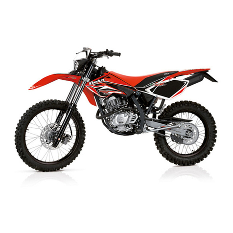
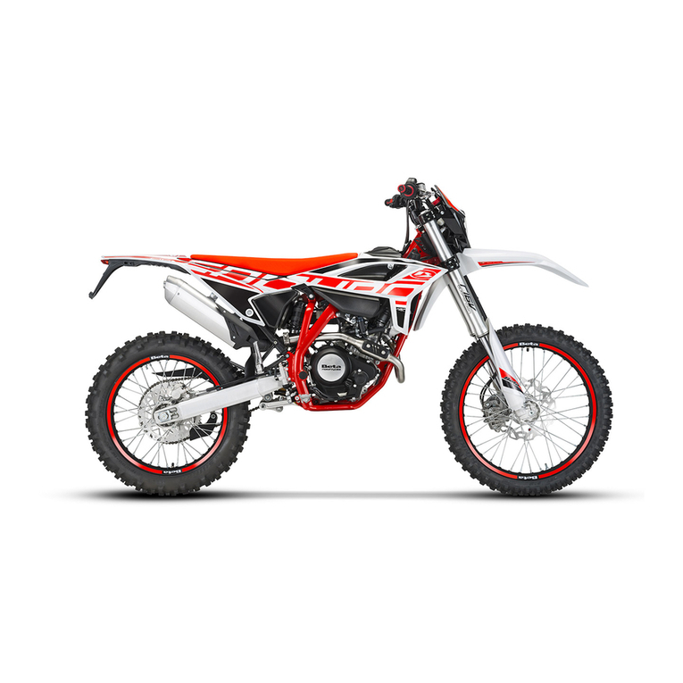
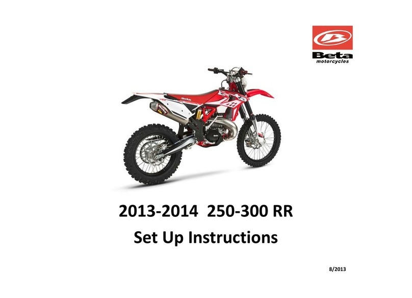
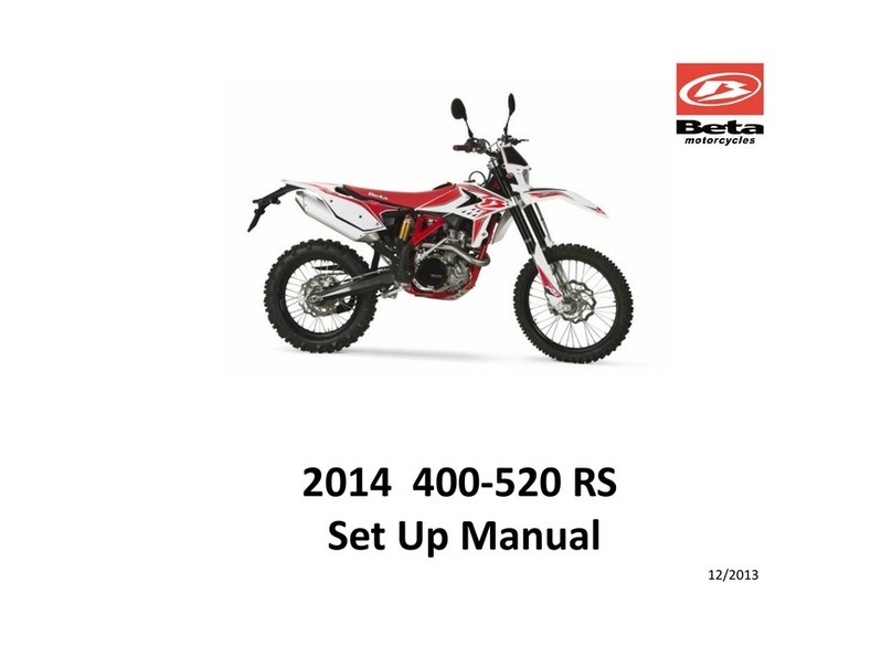
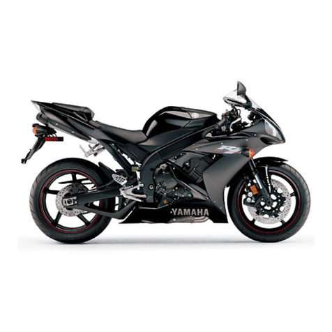
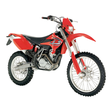
Beta RR 4T ENDURO 2014 350 User manual

RR 4 T 20 12
350 - 4 0 0 - 4 50 - 4 98

1GB
RR 350 - 400 - 450 - 498
Thanks for you preference, and have a good time! This hand-
book contains the information you need to properly operate and
maintain your motorcycle.
The data and specifications provided in this manual does not constitute an
engagement on the part of BETAMOTOR S.p.A. BETAMOTOR reserves the
right to make any changes and improvements to its models at any moment
and without notice.

2
GB
IMPORTANT
We recommend you to check all the tightenings after the first one
or two hours’ ride over rough ground. Special attention should
be paid to the following parts:
•rear sprocket
•ensure that the footrests are properly fixed
•front/rear brake levers/calipers/discs
•check that the plastics are properly fastened
•engine bolts
•shock absorber bolts/swingarm
•wheel hubs/spokes
•rear frame
•pipe connections
•tensioning the chain
IMPORTANT
For any servicing requirements, please get in contact with Beta-
motor’s authorized service network.

CONTENTS
3GB
Operating instructions.............................................................................. 5
Ecologic guide....................................................................................... 5
Riding safety.......................................................................................... 6
CHAPTER 1 GENERAL INFORMATION.............................................. 7
Vehicle identification data ........................................................................ 8
Delivery................................................................................................ 8
Load ................................................................................................. 10
Tyres .................................................................................................. 10
Steering lock ....................................................................................... 11
Familiarizing with your vehicle ................................................................ 12
Controls.............................................................................................. 13
Specifications ...................................................................................... 23
Wiring diagrams RR 4t ......................................................................... 27
Electrical devices.................................................................................. 29
Euro 3 devices..................................................................................... 30
CHAPTER 2 OPERATION ................................................................. 31
Checks to be performed before each ride ................................................. 32
Lubricants............................................................................................ 33
Running-in ........................................................................................... 33
Starting the engine................................................................................ 34
Choke and Idling setting........................................................................ 35
Refuelling............................................................................................ 36
CHAPTER 3 CHECKS AND MAINTENANCE..................................... 37
Motor oil level check............................................................................. 38
Changing the engine oil and filters extraction............................................. 39
Changing the gear and clutch oil ............................................................ 41
Check the level of the front and rear brake fluid and bleeding....................... 42
Check the front and rear brake pads........................................................ 44
Check the oil level in the hydraulic clutch and bleeding ............................... 45
Fork oil............................................................................................... 46
Air filter .............................................................................................. 49
Spark plug .......................................................................................... 50
Carburetor .......................................................................................... 52
Coolant.............................................................................................. 54
Drive chain maintenance and wear.......................................................... 55
Charging the battery............................................................................. 56
Cleaning and checking the vehicle .......................................................... 57
Scheduled maintenance......................................................................... 58
Prolonged inactivity............................................................................... 60
CONTENTS
4
GB
CHAPTER 4 ADJUSTMENTS............................................................. 61
Brake adjustment: front lever and brake pedal ........................................... 62
Adjusting the home position of the clutch lever............................................ 63
Adjusting the handlebars........................................................................ 63
Adjusting the throttle control cable............................................................ 64
Checking and adjusting the steering play.................................................. 64
Adjusting the Suspensions: telescopic fork and shock absorber.............. 65 ÷ 67
Tensioning the chain.............................................................................. 67
CHAPTER 5 REPLACEMENTS ........................................................... 69
Replacing the brake pads: front and rear ................................................. 70
Replacing the headlight bulbs ................................................................. 72
Replacing the rear optical batch ............................................................. 72
CHAPTER 6 TROUBLESHOOTING.................................................... 75
INDEX.............................................................................................. 77

5GB
OPERATING INSTRUCTIONS
•The vehicle must be accompanied by: number-plate, registration document, tax
disc and insurance.
•Do not carry animals, pets or loose objects that can stick out from the vehicle.
•Riding without a crash helmet is forbidden.
•Always ride with the low beam on.
•Any modifications of the engine or other parts resulting in a power and/or speed
increase are punishable by severe sanctions including the confiscation of the vehicle.
•To protect your safety and that of others, always drive carefully and with your helmet
on.
WARNING
Any modifications and tampering with the vehicle during the warranty period exempt
the manufacturer from all responsibility and invalidate warranty.
ECOLOGIC GUIDE
•Every vehicle powered by an internal combustion engine produces an amount of
noise (noise pollution) and gases (air pollution) which varies with the riding style.
•The abatement of noise and air pollution levels is the duty of everybody. Avoid
full-throttle starts, sudden acceleration and abrupt braking. This will reduce noise
emission as well as the wear and tear of the tyres and mechanical parts, and will
also allow a considerable reduction in fuel consumption.

6
GB
RIDING SAFETY
•Observe the Highway Code.
•Always put on and fasten a homologated helmet.
•Always ride with the low beam on.
•Always keep the crash helmet visor clean.
•Avoid wearing garments with hanging ends.
•Do not keep sharp or brittle objects in your pockets while riding.
•Properly adjust the rearview mirrors.
•Always ride in a seated position, with both hands on the handlebars and both feet
on the footrests.
•Always pay attention and do not allow anything to distract you while riding.
•Do not eat, drink, smoke, use a mobile phone, etc. while riding.
•Do not wear headphones to listen to music while riding.
•Never ride abreast with other vehicles.
•Do not tow and avoid being towed by other vehicles.
•Always keep a safe distance from other vehicles.
•Do not sit on the vehicle when it is on its stand.
•Do not start off while the vehicle is on its stand.
•Do not pull out the stand when the vehicle is facing downhill.
•Avoid swaying and wheelies as they are extremely dangerous for your own and
other people’s safety as well as for your vehicle.
•Always apply both brakes on dry roads with no gravel and sand. Using one brake
may be dangerous and cause uncontrolled skidding.
•To reduce the braking distance, always apply both brakes.
•On wet roads and in off-road riding, drive with care and at moderate speed. Take
special care in applying the brakes.
•Do not start the engine in closed places.

1
GENERAL INFORMATION
7GB
CONTENTS
CHAPTER 1 GENERAL INFORMATION
Vehicle identification data
Delivery
Load
Tyres
Steering lock
Familiarizing with your vehicle
Controls
Specifications
Wiring diagram
Electrical devices
Euro 3 devices

1
GENERAL INFORMATION
8
GB
VEHICLE IDENTIFICATION DATA
FRAME IDENTIFICATION
Frame identification data Aare stamped
on the right side of the steering head tube.
ENGINE IDENTIFICATION
Engine identification data Bare stamped
in the area shown in the figure.
WARNING:
Tampering with the identification numbers
is severely punished by law.
DELIVERY
•The vehicle is supplied ready for use.
However, it is advisable to conduct a few
simple checks before riding:
- Check the tyre pressures.
- Check the oil level in the engine.
•The following items are supplied as stand-
ard: operation and maintenance manual,
tool kit (see photo).
To take the tool kit, push the button 1to
get off the saddle. Pull back the saddle.
Pull the rear side panel 2to disassemble it.
A
B
1
2
4

1
GENERAL INFORMATION
9GB
Get off the male end wrenches and hexa-
gon socket 3.
With these is possible to unscrew the
screw 4.3
Pull the left cover of rear fender and unhook
two rubber bande 5. Now the toolkit 6
is accessibile.
5
5
6

1
GENERAL INFORMATION
10
GB
LOAD
•To avoid to let the vehicle be unstable, do not carry bulky or heavy objects.
•Do not carry objects that stick from the vehicle or cover the lighting and signalling
devices.
TYRES
•Only fit tyres approved by BETAMOTOR.
Unsuitable tyres can adversely affect the
road holding of the vehicle.
•To protect your safety, immediately re-
place any damaged tyres.
•Slick tyres adversely affect the road
holding of the vehicle, especially on wet
roads and in off-road riding.
•Insufficient pressure results in abnormal
wear and overheating of the tyres.
•The front and rear tyres must have the
same tread design.
pressure is too high
TYRES PRESSION ENDURO
RR 400 - 450 - 520
TYRE
Off-road
Road
rear
1,0 bar
1,8 bar
front
1,0 bar
1,5 bar
pressure is too low
pressure is correct

1
GENERAL INFORMATION
11 GB
Note
The type, condition and pressure of the tyres affect the road holding of the vehicle.
For this reason it is essential to check them before each journey.
•The size of the tyres is shown in the technical specifications and in the vehicle
handbook.
•Check the condition of the tyres before each journey. Inspect the tyres for cuts and
for nails or other pointed objects sticking out of them. Regarding the minimum al-
lowable thickness of the tread, observe the regulations in force in your country. We
recommend replacing the tyres at the latest when the tread is 2 mm thick.
•Check the inflating pressure on a regular basis while the tyres are cold. Proper
pressure ensures optimum riding comfort and prolongs the life of the tyres.
STEERING LOCK
The vehicle is supplied with one key and
a spare to be used for the steering lock.
WARNING:
Do not keep the spare keys in the vehicle.
Keep the keys in a safe and easy-to-reach
place. The code number stamped on the
keys should be copied on this manual (or
elsewhere) so it can be used to ask for
duplicates should both keys be lost.
To engage the steering lock, fully turn the
handlebars to the left, insert the key, press
and turn it fully anticlockwise and then
release it.

1
GENERAL INFORMATION
12
GB
FAMILIARIZING WITH THE VEHICLE
Main parts:
1 - Fuel tank
2 - Tank cap
3 - Silencer
4 - Rear shock absorber
5 - Headlight
6 - Rear light
7 - Side stand
8 - Fork
9 - Rider’s footrests
10 - Lower bumper
(Bumper kit)
11 - Saddle
12 - Engine
13 - Front mudguard
14 - Number-plate holder
15 - Kick-start
16 - Front side panel
17 - Rear side panel
18 - Fork covers
19 - Rear mudguard
20 - Cover air filter
5
8
21
11
19
14
12
97
6
34
17
15 10
13
16
18
20

1
GENERAL INFORMATION
13 GB
B
2
1
2
3456
3
4
CONTROLS
CLUTCH LEVER
Clutch lever 1is fitted to the left-hand side
of the handlebars. Screw Acan be used
to alter the home position of the lever (see
Adjustments).
FRONT BRAKE LEVER
Front brake lever 2is fitted to the right-hand
side of the handlebars. Screw Bcan be
used to adjust the home position of the
lever (see Adjustments).
GEARCHANGE LEVER
Gearchange lever 3is fitted to the left side
of the engine.
The positions corresponding to the different
gears are shown in the figure.
The neutral position is between the 1st and
2nd gears.
BRAKE PEDAL
Brake pedal 4is located in front of the
right-hand footrest.
The position of the pedal can be adjusted
to suit the requirements of the driver (see
Adjustments).
A
1

1
GENERAL INFORMATION
14
GB
DIGITAL RPM INDICATOR
BUTTONS
The instrument is equipped with four buttons which are required for its proper fun-
ctionality (Fig. 2). In their released positions, the buttons’ functions (Up, Down Mode
and Ctrl) are intended as OFF (N.A.).
The buttons’ functionalities are inhibited when the message “SPEED MAX” is shown
on the display.
FUNCTIONAL CHARACTERISTICS
Basic functions
These are the functions which can always be displayed and cannot be de-selected
from the Setup Menu; they also represent the output configuration with which every in-
strument produced by MAE is programmed. The basic functions include the following:
- Current speed (SPEED); this data is always visible, regardless of whether the vehicle
is stationary or in movement. The default configuration uses Km/h as the unit of
measure.
- Total distance travelled (ODO); this data can only be displayed by pressing the
mode button, regardless of whether the vehicle is stationary or in movement. The
default configuration uses Km as the unit of measure.
- Total vehicle operating time measured in hours (H); this data can only be displayed
by pressing the mode button, regardless of whether the vehicle is stationary or in
movement.

1
GENERAL INFORMATION
15 GB
Current speed function (SPEED)
This data is always displayed on the right hand portion of the screen, along with
the “SPEED“ function indicator and the selected unit of measure. The unit of measure
(km/h or mph) is indicated with the appropriate symbol and can be modified using
the methodology described farther ahead in this manual (see Setup Menu). If the
vehicle’s speed exceeds 110 km/h for more than 20 consecutive seconds, the
screen shown in the figure will be shown flashing on the display. At the same time,
the backlighting will also turn on and off intermittently.
This signal will remain on the screen until the vehicle’s speed goes below 110 km/h
for at least 10 consecutive seconds. Note: while the alarm and message is being
displayed, the buttons’ functionalities will be inhibited.
Odometer Function (ODO)
The data is displayed on the left hand portion of the screen, along with the “ODO”
function indicator. The total distance travelled by the vehicle is always calculated in
km. Nevertheless, the relative value can be displayed in either km or miles (see the
section regarding the Setup Menu).
H Function
This function describes the correct functionality/display of the H function. This fun-
ction indicates the vehicle’s total operating time in hours and can be displayed by
pressing the mode button. When selected, this data is always displayed on the left
hand portion of the screen. The data cannot be reset under the instrument’s normal
operating conditions. The data is displayed with a precision of 0.1 hours. In addition
to the basic functions, the user can also access the Setup Menu to enable others.

1
GENERAL INFORMATION
16
GB
The time can be adjusted while the vehicle is stationary by holding down the Mode
button (while the CLK function is being displayed) until the screen illustrated in the
figure appears on the display. Use the Mode button to sequentially select the hours,
minutes, seconds and display mode (the data will be displayed flashing); at this
point the data selected using the Mode button can be adjusted by pressing the Up
and Down buttons. When finished adjusting the time settings, hold down the Mode
button to return to normal operating mode.
Automatic trip function (TR1)
The displayed data represents the partial distance travelled by the vehicle; based
on the selected configuration, the data is expressed in either km or miles (see the
indications provided in the section regarding the Setup Menu). The counter associated
with this parameter can be reset by holding down the Mode button (while the TR1
function is being displayed) until the value on the screen is set to 000.0 (see the
section of this Manual entitled Button Functions). The TR1 parameter can be reset
both while the vehicle is stationary, as well as while it is in movement. The value of
TR1 is NOT saved to the permanent memory.
Current time function (CLK)
This function describes the correct functionality/display of the current time function.
When selected, this function is always expressed in the format “hh:mm:ss”.
Automatic timer function (S1)
When selected, the data is displayed as shown in the figure, along with the “S1”
function indicator.

1
GENERAL INFORMATION
17 GB
This data represents the vehicle’s actual travel time, in the format “hh:mm:ss”, as-
sociated with the parameters “A1” and “TR1”; it is therefore an automatic counter;
the timer function starts automatically with the first impulse received from the speed
sensor (the colons which separate the hours, minutes and seconds will be displayed
flashing while TR1 is enabled and will be displayed fixed while TR1 is not enabled)
and stops automatically after receiving the last impulse from the speed sensor. The
counter associated with this parameter can be reset by holding down the Mode
button (while the S1 function is being displayed) until the value on the screen is set
to 00:00:00. The value of S1 is NOT saved to the permanent memory
Automatic average speed function (A1)
This function describes the correct functionality/display of the average speed asso-
ciated with TR1 and S1. When selected, the data is displayed as shown in Fig.11,
along with the “A1” function indicator. The data represents the average speed
maintained by the vehicle (expressed in km/h or mph based on the selected unit
of measure), calculated as the ratio between the distance travelled (represented by
TR1) and the time in which the distance has been covered (represented by S1). The
average speed is recalculated every 0.1 km (or 0.1 miles based on the selected
unit of measure) travel by the vehicle. The counter associated with this parameter
can be reset by holding down the Mode button (while the A1 function is being
displayed) until the value on the screen is set to 0.0 (see the section of this Manual
entitled Button Functions).
The resetting of the A1 parameter can be performed both while the vehicle is station-
ary as well as while it is in movement and also causes the TR1 and S1 parameters
to be reset. If the data to be displayed exceeds the value of 512, the character
-- -- -- -- will be displayed. The value of A1 is NOT saved to the permanent memory.
Manual timer function (LAP)
This function describes the correct functionality/display of the manual LAP timer function.
When selected, the data is displayed as shown in the figure, along with the “LAP”
function indicator. Once displayed (in the format “hh:mm:ss”), the timer can be acti-
vated by pressing the Up button. Press the same button once again to stop the timer.
The Start/Stop procedure can be performed both while the vehicle is stationary, as
well as while it is in movement.

1
GENERAL INFORMATION
18
GB
Function TR2
This function describes the correct functionality/display of the TR2 on board odo-
meter. When selected, the data is displayed as shown in the figure; the displayed
value represents the distance travelled by the vehicle. In contrast to TR1, the value
of TR2 can be modified manually using the button panel; in particular, the TR2 value
can be increased by pressing the Up button and decreased by pressing the Down
button. The counter associated with this parameter can be reset by holding down
the Mode button for about 1 sec. (while the TR2 function is being displayed). The
value of TR2 is NOT saved to the permanent memory.
The activation of the LAP function is nevertheless signalled to the user by means of
flashing colons between the displayed hours, minutes and seconds, if the LAP function
is being displayed, otherwise the “LAP” function indicator will be displayed flashing;
if the timer is in start mode, up to 10 partial times can be saved to a temporary
memory (for subsequent review) by simply pressing the Down button; the displayed
value will be reset, indicating to the user that the displayed LAP value has been sa-
ved to the temporary memory. Once 10 partial times (maximum) have been saved,
pressing the Down button will not produce any effect. The counter associated with
this parameter can be reset (without saving any data to memory) by holding down
the Mode button (while the LAP function is being displayed) until the value on the
screen is set to 00:00:00. The resetting of the LAP parameter can be performed
both in Start mode as well as in Stop mode and will cause all of the previously saved
partial times to be deleted.
Manual timer function (S2)
This function describes the correct functionality/display of the manual timer function
associated with S2. When selected, the data is displayed as shown in the Figure
15, along with the “S2” function indicator. This data represents the vehicle’s travel
time, in the format “hh:mm:ss”; in contrast to S1, this is a Manual counter: the timer
can be started by pressing the Up button (the colons between the hours, minutes
and seconds are flashing when S2 is in function and are fixed while S2 is not in
function) and stopped by pressing the same button once again. The resetting of
the S2 parameter can be performed both while the vehicle is stationary as well as

1
GENERAL INFORMATION
19 GB
while it is in movement and will not cause the TR2 parameter to be reset. The value
of S2 is NOT saved to the permanent memory.
Average speed function A2
This function describes the correct functionality/display of the average speed
associated with TR2 and S2. When selected, the data is displayed as shown in
the figure, along with the “A2” function indicator. The data represents the average
speed maintained by the vehicle (expressed in km/h or mph based on the selected
unit of measure), calculated as the ratio between the distance travelled (represented
by TR2) and the time in which the distance has been covered (represented by S2).
If the data to be displayed exceeds the value of 512, the character -- -- -- -- will be
displayed. The value of A2 is NOT saved to the permanent memory.
Maximum Speed Function (MAX)
This function describes the correct functionality/display of the maximum speed fun-
ction. When selected, the data is displayed as shown in the figure, along with the
“MAX” function indicator. The parameter identifies the maximum speed reached by
the vehicle, expressed in km/h or mph based on the selected unit of measure. The
counter associated with this parameter can be reset by holding down the Mode
button (while the MAX function is being displayed) until the value on the screen is
set to 0.0. The MAX parameter can be reset both while the vehicle is stationary, as
well as while it is in movement.
Other manuals for RR 4T ENDURO 2014 350
1
This manual suits for next models
11
Table of contents
Other Beta Motorcycle manuals

Beta
Beta Evo4t 300 User manual

Beta
Beta Rev 4T User manual

Beta
Beta ALP 200 User manual

Beta
Beta RR 525 User manual

Beta
Beta RR 350 EFI User manual

Beta
Beta RR 50 cc ENDURO User manual

Beta
Beta REV 3 User manual

Beta
Beta RR 2T 2013 User manual

Beta
Beta 125 RR-S 2020 User manual

Beta
Beta RR 50 CC ENDURO User manual

Beta
Beta TECHNO 250 User manual

Beta
Beta EVO 2T User guide

Beta
Beta Evo 2T 2011 User manual

Beta
Beta RR 4T ENDURO 2014 350 Guide

Beta
Beta EVO 4T 2012 User manual

Beta
Beta REV 80 User manual

Beta
Beta MINITRIAL 50 User manual

Beta
Beta REV 50 User manual

Beta
Beta RR 250 2T EUROPA 2019 User manual

Beta
Beta RR 125 4T 2011 User manual