Beta RR 4T-250 Instruction manual

WORKSHOP MANUAL
RR 4T - 250 - 400 - 450 - 525

3
INTRODUCTION
This publication has been designed to assist authorized
service personnel of Betamotor Workshops in maintaining
and repairing the vehicle referred to in the manual. Famil-
iarity with the specifications contained herein is a key fac-
tor in the technical training of operators. In order to make
the manual easy to read and understand, the different
paragraphs are marked with icons that point out the subject
dealt with.
USEFUL ADVICE
To avoid problems and ensure best results, Betamotor
recommends observing the following guidelines:
- Whenever a repair is needed, analyse the customer’s ac-
count of the malfunction and ask any questions that can
help to clarify the symptoms.
- Clearly diagnose the causes of the malfunction. This
manual provides basic operating principles which the op-
erator will have to supplement with their personal experi-
ence.
- Carefully plan the repair so as to avoid wasting time in
obtaining spare parts, preparing tools, etc.
- Gain access to the parts to be repaired by performing on-
ly the operations that are strictly necessary. For best re-
sults, always follow the removal procedures described in
this manual.
Note
Betamotor is committed to constantly improving its prod-
ucts. For this reason, there can be slight differences be-
tween the content of this manual and the vehicle to be re-
paired or serviced. Betamotor products are exported to
many countries characterized by different Highway Codes
and type-approval procedures. In view of this, Betamotor
reserves the right to modify its products and technical doc-
umentation at any time and without notice.
Let us help protect the environment
Everything we do affects the entire planet and its re-
sources.
To protect the common interest, Betamotor urges its cus-
tomers and service operators to use the vehicles and dis-
pose of their components in compliance with applicable
regulations on environmental pollution control, waste dis-
posal and recycling.

4
GENERAL CONTENTS
1 General information
2 Specific tools
3 Tightening torques - Specifications -
Recommended products
4 Maintenance
5 Bodywork and fittings
6 Engine
7 Carburettor
8 Front suspension/wheel
9 Rear suspension/wheel
10 Braking system
11 Electrical system
Workshop manual RR 4T - 250 - 400 - 450 - 525

6Workshop manual RR 4T - 250 - 400 - 450 - 525
CONTENTS
HOW TO CONSULT THE MANUAL . . . . . . . Chap. 1 - 7
GENERAL CONTENTS . . . . . . . . . . . . . Chap. 1 - 7
Arrangement of subjects . . . . . . . . . . . Chap. 1 - 7
Description of operations . . . . . . . . . . . Chap. 1 - 7
PURPOSE OF THE MANUAL . . . . . . . . . . . Chap. 1 - 7
Updates . . . . . . . . . . . . . . . . . . . . . . . . . Chap. 1 - 7
TERMS AND SYMBOLS . . . . . . . . . . . . . . Chap. 1 - 8
CONVENTION . . . . . . . . . . . . . . . . . . . . . . Chap. 1 - 9
SAFETY . . . . . . . . . . . . . . . . . . . . . . . . . . Chap. 1 - 10
Carbon monoxide . . . . . . . . . . . . . . . . Chap. 1 - 10
Petrol . . . . . . . . . . . . . . . . . . . . . . . . . . Chap. 1 - 10
Engine oil . . . . . . . . . . . . . . . . . . . . . . Chap. 1 - 10
Coolant . . . . . . . . . . . . . . . . . . . . . . . . Chap. 1 - 10
Brake fluid . . . . . . . . . . . . . . . . . . . . . . Chap. 1 - 11
Threadlocking fluid . . . . . . . . . . . . . . . Chap. 1 - 11
Shock absorber nitrogen . . . . . . . . . . Chap. 1 - 11
Battery . . . . . . . . . . . . . . . . . . . . . . . . . Chap. 1 - 11
Hot parts . . . . . . . . . . . . . . . . . . . . . . . Chap. 1 - 11
NOTES . . . . . . . . . . . . . . . . . . . . . . . . . . . Chap. 1 - 12
TABLES OF CONTENTS
TABLE OF CONTENTS OF EACH CHAPTER
Chap. 1 - 12
CONTENTS OF EACH CHAPTER . . . . . . . Chap. 1 - 12
OPERATING SPECIFICATIONS . . . . . . . . Chap. 1 - 13
VEHICLE IDENTIFICATION . . . . . . . . . Chap. 1 - 13

7
1 - General information Release 00 Date 02/2005
HOW TO CONSULT THE MANUAL
Arrangement of subjects
The manual is divided into chapters that cover the main sub-
assemblies of the vehicle. To make the different chapters easy
to find, the pages of each chapter bear a reference mark that is
aligned with the related title in the general contents.
Description of operations
The removing, fitting and checking operations described in the
manual are accompanied by pictures (drawings or pho-
tographs).
The pictures contain symbols referring to procedures, special
tools and other information. Refer to the key to the symbols for
a description of their meanings.
The procedures are arranged sequentially, step by step.
EXAMPLE
Whenever a specific tightening torque is needed, begin by ap-
plying a standard tightening torque (e.g. 10 N·m), then proceed
with the tightening by rotating the part by a predetermined angle
(e.g. 30°).
PURPOSE OF THE MANUAL
This manual is chiefly intended for qualified Betamotor dealers and mechanics. A mechanic should not expect to find all
the information he requires in a manual. Anybody who uses this manual should have a working knowledge of the princi-
ples of mechanics and of motorcycle repairing techniques. Performing repairs or maintenance operations without this
knowledge may render the vehicle unusable and even dangerous.
Updates
Betamotor is committed to continually improving its products. Any significant changes made to the specifications and pro-
cedures contained in this manual will be made known to official dealers and will be included in future editions of the man-
ual. All the information, instructions and technical data provided in this manual were up-to-date when the manual was ap-
proved for print. Betamotor reserves the right to make changes to the manual at any time, without notice and without in-
curring any obligations.
30°
10 N·m
GENERAL CONTENTS

8
TERMS AND SYMBOLS
Workshop manual RR 4T - 250 - 400 - 450 - 525
When performing these oper-
ations, flammable vapours
can be released and metal
parts can be ejected at high
speed. It is therefore neces-
sary to:
- Avoid working near sparks
or open flames.
- Wear protective clothing.
- Wear protective goggles.
IMPORTANT
Whenever a worn cylinder
part needs to be replaced,
we recommend checking
and if necessary replacing all
the parts that are related to it.
In particular, the following
parts should always be re-
placed at the same time:
- Piston, piston rings and
piston pins.
- Valves, valve springs,
valve cotters, caps and
thrust washers.
- Valve guides with related
valves, springs, caps,
valve cotters and thrust
washers.
- Crankshaft bearings.
- Any part subject to even
wear.
To keep the engine in perfect
running order, ensure that all
fits are within the prescribed
tolerances. A close fit can
lead to seizure as soon as
the moving parts heat up; on
the other hand, a loose fit
causes vibrations that accel-
erate the wear and tear of
moving parts.
NOTE Whenever the words left, right, upper,
lower, front and rear are used, reference
is made to the vehicle in its normal direc-
tion of travel.
Avoid disposing of the parts in the envi-
ronment.
NOTE

9
1 - General information Release 00 Date 02/2005
CONVENTION
In order to clarify the left/right convention used in this manual, a diagram of the vehicle and engine are provided below
with an indication of how the two sides are referred to in the manual.
Rh
Rh
Lh
Lh
FouP5troke

10 Workshop manual RR 4T - 250 - 400 - 450 - 525
SAFETY
Carbon monoxide
• Exhaust gases contain carbon monoxide (CO), a poisonous gas that can cause loss of consciousness and even death.
• Before starting the engine, ensure that the area is well ventilated. Never run the engine indoors.
• The engine can be run indoors only if the area is equipped with specially designed exhausters.
Petrol
• Petrol is highly flammable and, under certain circumstances, explosive.
• Keep all heat sources, sparks and open flames away from the working area.
• Always work in a well ventilated area.
• Never use petrol as a cleaning solvent. Avoid handling it unless absolutely necessary.
• Do not use petrol for cleaning components that need to be blown with compressed air.
• Keep out of the reach of children.
Engine oil
• Repeated and prolonged contact of engine oil with the skin can cause skin diseases.
• In case of contact, wash the contaminated parts with soap and water as soon as possible.
• In case of eye contact, rinse abundantly with water and seek medical attention.
• In case of ingestion, immediately seek medical attention without causing vomit as this could result in the oil being
breathed into the lungs. If the product is believed to have been breathed into the lungs, immediately transport the af-
fected person to the nearest hospital.
• Spent oil contains substances that are dangerous to the environment. Oil can be renewed only by operators that are
equipped for the disposal of spent oils in compliance with applicable laws.
• Avoid disposing of spent oil in the environment.
• Keep out of the reach of children.
Coolant
• Under certain circumstances the ethylene glycol contained in the coolant is flammable and its flame is invisible. Should
the ethylene glycol ignite, its flame, though invisible, could cause serious burns.
• Avoid bringing the coolant into contact with hot parts as these could ignite it.
• The coolant (ethylene glycol) can irritate the skin and is poisonous if ingested.
• In case of skin contact, immediately take off any contaminated clothes or footwear and wash abundantly with soap and
water. In case of eye contact rinse abundantly with clean water and immediately seek medical attention. If the coolant
is ingested, avoid causing vomit as this could cause the product to be breathed into the lungs. Administer clean water
and immediately transport the affected person to the nearest hospital and show the product to health personnel.
• If anybody is exposed to a high concentration of coolant vapours, transport them to an area where they can breath un-
polluted air. If necessary seek medical assistance.
• Do not remove the radiator cap when the engine is hot. Since the coolant in the radiator is subjected to high pressures,
it could spurt out and cause burns.
• The coolant contains substances that are harmful to the environment. The coolant can only be renewed by operators
equipped for the disposal of spent oils/coolant in compliance with the regulations in force.
• Avoid disposing of the coolant in the environment.
• Keep out of the reach of children.
WARNING The information contained in this paragraph is designed to minimize the risks the operator runs
when working on the vehicle.

11
1 - General information Release 00 Date 02/2005
Brake fluid
• The brake fluid is highly corrosive.
• Avoid contact with the eyes, the skin and the mucous
membranes.
• In case of skin contact, immediately take off any conta-
minated clothes or footwear and wash abundantly with
soap and water.
• In case of eye contact, rinse abundantly with water and
seek medical attention.
• In case of ingestion, immediately seek medical attention
without causing vomit as this could cause the oil to be
breathed into the lungs.
• If the product is believed to have been breathed into the
lungs, immediately transport the affected person to the
nearest hospital.
• If anybody is exposed to a high concentration of coolant
vapours, transport them to an area where they can
breath unpolluted air. If necessary seek medical assis-
tance.
• In case of accidental contact, rinse abundantly with wa-
ter and seek medical attention.
• Keep out of the reach of children.
Threadlocking fluid
• Although threadlocking fluid is not classified as danger-
ous, prolonged contact with the skin, especially if
bruised, can lead to sensitization or dermatitis. In case of
skin contact, rinse with running water.
• In case of sickness due to inhalation of the product, take
the affected person into the open air and seek medical
assistance.
• In case of eye contact, rinse abundantly with water for at
least 15 minutes.
• In case of ingestion, drink large quantities of water or
milk. Seek medical attention without causing vomit as
this could cause the oil to be breathed into the lungs.
• Keep out of the reach of children.
Shock absorber nitrogen
• The rear shock absorber contains pressurized nitrogen.
• Before disposing of used shock absorbers, release the
nitrogen through the inflating valve.
• Only use nitrogen to pressurize the shock absorber. Un-
stable gases can explode and cause burns.
• To prevent the risk of explosions and burns, avoid keep-
ing the shock absorber close to flames or heat sources.
• Keep out of the reach of children.
Battery
• The battery produces explosive gases. Keep it away
from sparks, flames and cigarettes. Only recharge it in
well ventilated places.
• The battery contains a solution of sulphuric acid (elec-
trolyte).
• Sulphuric acid is corrosive to many materials and
clothes. When it comes into contact with small quantities
of water it produces a violent reaction which releases in-
tense heat and spurts of hot acid. Sulphuric acid attacks
many metals and in the process releases hydrogen, a
flammable gas that combines with air to produce an ex-
plosive mixture.
• Contact with sulphuric acid can cause burns. In case of
contact immediately take off any contaminated garments
and rinse the skin with large quantities of water. If nec-
essary, take the affected person to the nearest hospital.
• In case of eye contact immediately rinse abundantly with
water, seek medical assistance and continue the treat-
ment until the doctor arrives.
• Should the electrolyte be ingested, rinse the mouth with
water without swallowing, immediately transport the af-
fected person to the nearest hospital and show the prod-
uct to health personnel.
• The battery contains dangerous substances that are
harmful to the environment. Batteries can only be re-
placed by operators equipped for their disposal in com-
pliance with the regulations in force.
• Avoid disposing of spent batteries in the environment.
• Keep out of the reach of children.
Hot parts
• The engine and the exhaust system become and remain
very hot for some time, even after the engine has been
stopped. Allow them to cool down and put on insulating
gloves before handling these parts or working near them.
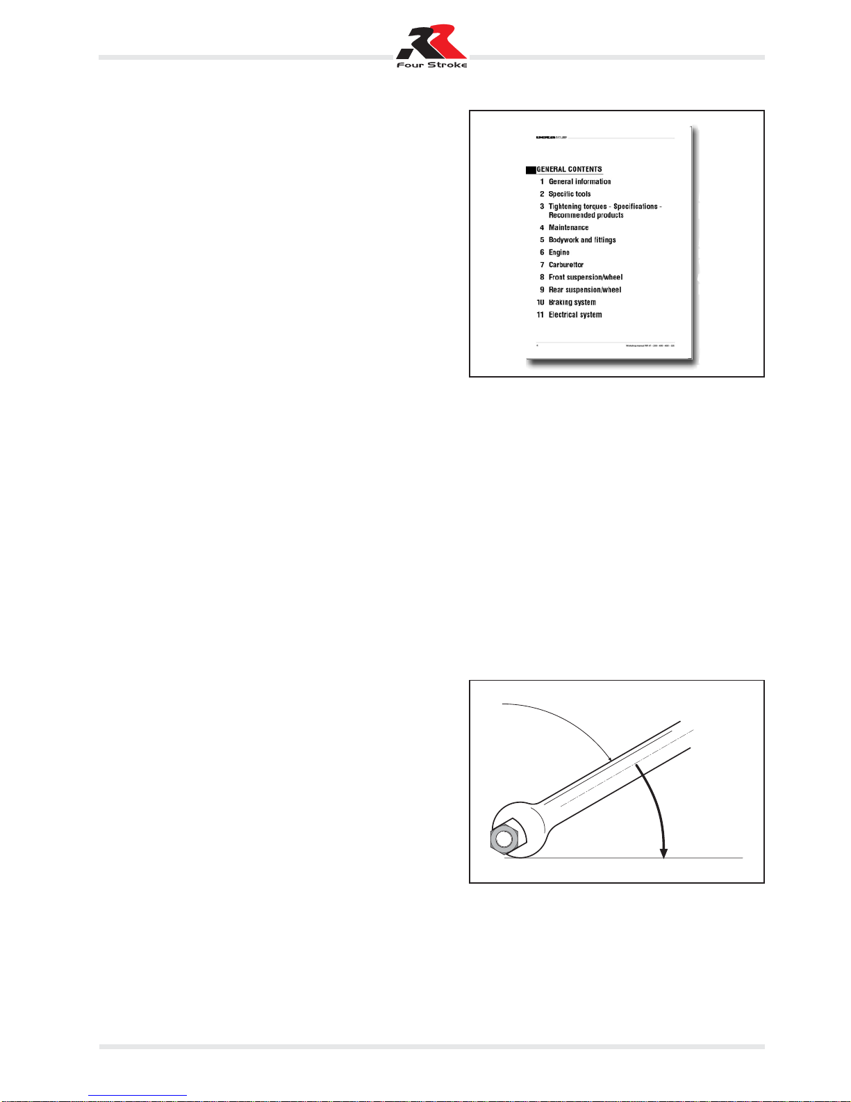
13
1 - General information Release 00 Date 02/2005
2) engine number
3) type-approval data
OPERATING SPECIFICATIONS
VEHICLE IDENTIFICATION
The frame number is stamped on the right side of the head tube.
The engine number is stamped on the upper crankcase half, next to the swingarm.
ZD3 E1 XX XXXXXXXXXX
Manufacturer’s data
Vehicle model
Version 00 (250 cc)
01 (400 cc)
02 (450 cc)
03 (525 cc)
The following is an example of frame number format:
1) frame number

3
SPECIFICATIONS - ENGINE
SPECIFICATIONS
Engine 250 400 450 525
Type single-cylinder, 4-stroke, liquid-cooled, with countershaft and electric start
Displacement 250 cc 398 cc 448 cc 510 cc
Bore/stroke 75 / 56,5 mm 89 / 64 mm 89 / 72 mm 95 / 72 mm
Compression ratio 12 : 1 11 : 1 11 : 1 11 : 1
Fuel unleaded premium fuel with a minimum of 95 RON
Valve gear 4 rocker-operated valves and 1 overhead camshaft driven by single chain
Camshaft 5532 590/5521 590/5521 590/5521
Diameter of intake valves 28 mm 35 mm 35 mm 35 mm
Diameter of exhaust valves 24 mm 30 mm 30 mm 30 mm
Valve cold clearance intake: 0,12 mm
Valve cold clearance exhaust: 0,12 mm
Crankshaft bearings 2 cylindrical roller bearings
Small end bearing needle roller cage
Small end bearing bronze bearing
Piston cast alloy forged alloy
Piston rings 1 compression ring, 1 scraper ring
Lubrication 2 oil pumps
Engine oil completely synthetic oil of known brands (Motorex Cobra 15W40)
Oil quantity 1,25 litres
Primary drive cylindrical gears with straight teeth, 33:76 teeth
Clutch wet multiplate
Transmission (with front coupling) 6 speed 6 speed 6 speed 6 speed
Gear ratios 1st 14:38 1st 14:34 1st 14:34 1st 14:34
2nd 16:36 2nd 17:31 2nd 17:31 2nd 17:31
3rd 19:34 3rd 19:28 3rd 19:28 3rd 19:28
4th 21:32 4th 22:26 4th 22:26 4th 22:26
5th 23:30 5th 24:23 5th 24:23 5th 24:23
6th 22:25 6th 26:21 6th 26:21 6th 26:21
Ignition system DC-CDI digital ignition system without breaker, with variable spark advance, KOKUSAN type
Dynamo 12V 150W 12V 150W 12V 150W 12V 150W
Spark plug NGK DCPR 8 E
Spark gap 0,6 - 0,7 mm
Cooling liquid cooling, forced liquid circulation by pump
Coolant 1.3 litres, 40% antifreeze, 60% water, at least -25°C
Starting electric start / kickstart
3 - Tighening torques, specifications, recommended products Release 00 Date 02/2005

4Workshop manual RR 4T - 250 - 400 - 450 - 525
SPECIFICATIONS - ENGINE
CARBURETTOR TUNING
250 400/450 525
Carburettor type Keihin FCR-MX 37 Keihin FCR-MX 39 Keihin FCR-MX 39
Carburettor code 3700A 3900A 3900B
Main jet 160 178 178
Jet needle OBEKT OBDVR OBDVT
Idling jet 42 42 42
Main air jet 200 200 200
Idling air jet 100 100 100
Needle valve position 3. 3. 3.
Starting jet 85 85 85
Fuel mixture adj. screw open by 0,75 turns 1,25 turns 1,25 turns
Throttle valve 15 15 15
Power reduction throttle valve stop throttle valve stop throttle valve stop
Pump diaphragm stop 858 / 2,15 mm 858 / 2,15 mm 858 / 2,15 mm

5
3 - Tighening torques, specifications, recommended products Release 00 Date 02/2005
SPECIFICATIONS - ENGINE
TIGHTENING TORQUES
Description Type Tightening
Crankcase, clutch cover, ignition cover flange screws M6 10 N·m
Oil drain screw M12x1.5 20 N·m
Short oil unit socket-head screw M16x1.5 10 N·m
Long oil unit hexagonal-head screw M20x1.5 15 N·m
Oil filter cover flange screw M5 6 N·m
Bypass valve screw M12x1.5 20 N·m
Oilway screw and oil line hollow grub screw M8 10 N·m
Oil pump cover screws M5 Loctite 222 + 6 N·m
Cylinder head flange screws - upper section M6 10 N·m
Cylinder head flange screws - upper section, water pump cover M6 8 N·m
Exhaust flange screws M6 Loctite 243 + 8 N·m
Cylinder head screws M10 40/50 N·m
Camshaft gear socket-head screws M8 Loctite 243 + 28 N·m
Automatic decompressor lever set screw M5 Loctite 222 + 8 N·m
Rocker arm pin socket-head end screw M5 5 N·m
Valve adjusting screw counternuts M6x0.75 11 N·m
Primary drive gear and free wheel socket-head screw M6 Loctite 646 + 16 N·m
Primary drive gear hexagonal nut M20x1.5 Loctite 243 + 150 N·m
Countershaft gear socket-head screws M6 Loctite 243 + 8 N·m
Clutch hub hexagonal nut M18x1.5 Loctite 243 + 150 N·m
Clutch spring flange screws M6 8 N·m
Gear selector socket-head screw M6 Loctite 243 + 10 N·m
Selector lever flange screw M5 Loctite 243 + 6 N·m
Timing chain stretcher, chain guide, chain guard flange screws M6 Loctite 243 + 8 N·m
Gearbox desmodromic mechanism flange screw M5 Loctite 243 + 6 N·m
Chain stretcher flange screws M6 8 N·m
Chain guard flange screws M5 Loctite 243 + 6 N·m
Stator flange screws M6 Loctite 243 + 8 N·m
Pick-up flange screws M5 Loctite 243 + 6 N·m
Rotor flange nut M12x1 60 N·m
Kickstart stop plate flange screw M6 Loctite 243 + 8 N·m
Kickstart spring link flange screw M6 Loctite 243 + 10 N·m
Starter motor cover flange screw, LH only M6 Loctite 243 + 8 N·m
Breather pipe bracket flange screw M6 Loctite 243 + 8 N·m
Kickstart screw M8 Loctite 243 + 25 N·m
Gearshift lever flange screw M6 Loctite 243 + 10 N·m
Hexagonal-head chain front sprocket screw M10 Loctite 243 + 60 N·m
Spark plug M10 10-12 N·m
Spark plug M12x1.25 20 N·m

6Workshop manual RR 4T - 250 - 400 - 450 - 525
SPECIFICATIONS - ENGINE
FITS, WEAR LIMITS
Crankshaft axial play . . . . . . . . . . . . . . . . . . . . . . . . . . . . . . . . . . . .0,1 - 0,2 mm
offset between shaft sections . . . . . . . . . . . . . . . . . . . .max. 0,12 mm
Small end bearing radial play . . . . . . . . . . . . . . . . . . . . . . . . . . . . . . . . . .max. 0,05 mm
axial play . . . . . . . . . . . . . . . . . . . . . . . . . . . . . . . . . . .max. 1,10 mm
Cylinder 250 size I diameter . . . . . . . . . . . . . . . . . . . . . . . . . .75,000 - 75,012 mm
size II diameter . . . . . . . . . . . . . . . . . . . . . . . . . .75,013 - 75,025mm
Cylinder 450/450 size I diameter . . . . . . . . . . . . . . . . . . . . . . . . . .89,000 - 89,012 mm
size II diameter . . . . . . . . . . . . . . . . . . . . . . . . . .89,013 - 89,025mm
Cylinder 525 size I diameter . . . . . . . . . . . . . . . . . . . . . . . . . .95,000 - 95,012 mm
size II diameter . . . . . . . . . . . . . . . . . . . . . . . . .95,013 - 95,025 mm
Piston 250 size I diameter . . . . . . . . . . . . . . . . . . . . . . . . . .74,960 - 74,970 mm
size II diameter . . . . . . . . . . . . . . . . . . . . . . . . .74,971 - 74,980 mm
size I fit . . . . . . . . . . . . . . . . . . . . . . . . . . . . . . . . .0,030 - 0,052 mm
size II fit . . . . . . . . . . . . . . . . . . . . . . . . . . . . . . . . .0,032 - 0,055 mm
wear limit . . . . . . . . . . . . . . . . . . . . . . . . . . . . . . . . . . . . . . .0,12 mm
Piston 400 size I diameter . . . . . . . . . . . . . . . . . . . . . . . . . .88,930 - 88,940 mm
size II diameter . . . . . . . . . . . . . . . . . . . . . . . . .88,941 - 88,950 mm
size I fit . . . . . . . . . . . . . . . . . . . . . . . . . . . . . . . . .0,060 - 0,082 mm
size II fit . . . . . . . . . . . . . . . . . . . . . . . . . . . . . . . . .0,062 - 0,085 mm
wear limit . . . . . . . . . . . . . . . . . . . . . . . . . . . . . . . . . . . . . . .0,12 mm
Piston 450 size I diameter . . . . . . . . . . . . . . . . . . . . . . . . . .88,916 - 88,946 mm
size II diameter . . . . . . . . . . . . . . . . . . . . . . . . .88,926 - 88,956 mm
size I fit . . . . . . . . . . . . . . . . . . . . . . . . . . . . . . . . .0,054 - 0,096 mm
size II fit . . . . . . . . . . . . . . . . . . . . . . . . . . . . . . . . .0,056 - 0,099 mm
wear limit . . . . . . . . . . . . . . . . . . . . . . . . . . . . . . . . . . . . . . .0,12 mm
Piston 525 size I diameter . . . . . . . . . . . . . . . . . . . . . . . . . .94,932 - 94,960 mm
size II diameter . . . . . . . . . . . . . . . . . . . . . . . . .94,940 - 94,968 mm
size I fit . . . . . . . . . . . . . . . . . . . . . . . . . . . . . . . . .0,050 - 0,070 mm
size II fit . . . . . . . . . . . . . . . . . . . . . . . . . . . . . . . . .0,044 - 0,085 mm
wear limit . . . . . . . . . . . . . . . . . . . . . . . . . . . . . . . . . . . . . . .0,12 mm
Luce segmento compression ring . . . . . . . . . . . . . . . . . . . . . . . . . . . . .max. 0,80 mm
scraper ring . . . . . . . . . . . . . . . . . . . . . . . . . . . . . . . . .max. 1,00 mm
Valves width of sealing surface, intake . . . . . . . . . . . . . . . . . .max. 1,50 mm
width of sealing surface, exhaust . . . . . . . . . . . . . . . . .max. 2,00 mm
head floating . . . . . . . . . . . . . . . . . . . . . . . . . . . . . . . .max. 0,05 mm
valve guide diameter . . . . . . . . . . . . . . . . . . . . . . . . . . .max. 6,2 mm
spring cup . . . . . . . . . . . . . . . .min. 0,4 mm (mm when new 0,5 mm)
Valve springs 450 / 525 /400 minimum outer spring length . . . . . . . . . . . . . . . . . . . . . . .39,20 mm
minimum inner spring length . . . . . . . . . . . . . . . . . . . . . . .36,45 mm
Conical valve springs 250 minimum length . . . . . . . . . . . . . . . . . . . . . . . . . . . . . . . . .37,70 mm
Oil pump play btw outer rotor and pump casing . . . . . . . . . . . . .max. 0,20 mm
play btw outer and inner rotors . . . . . . . . . . . . . . . . . .max. 0,20 mm
axial play . . . . . . . . . . . . . . . . . . . . . . . . . . . . . . . . . . . . . . .0,15 mm
By-bass valve minimum spring length . . . . . . . . . . . . . . . . . . . . . . . . . . . . .23,5 mm
Clutch plates minimum spring length . . . . . .min. 41,5 mm (mm when new 43 mm)
wear limit . . . . . . . . . . . . . . . . . . . . . . . . . . . . . . . . . . . . . . . .1,7 mm
Gear shafts axial play . . . . . . . . . . . . . . . . . . . . . . . . . . . . . . . . . . . .0,1 - 0,4 mm
Rocker arm shafts axial play . . . . . . . . . . . . . . . . . . . . . . . . . . . . . . . . . .0,02 - 0,10 mm
Countershafts support pin offset . . . . . . . . . . . . . . . . . . . . . . . . . . . . . . . . .0,06 mm

7
STANDARD ADJUSTMENTS - FORK
MARZOCCHI
Compression adjust range 18 clicks
Rebound adjust range 10 clicks
Oil type EB-H16 SAE 7,5
STANDARD ADJUSTMENTS - SHOCK ABSORBER
SACHS
Compression adjust range
clicks 21/21 (low speed)
clicks 24/24 (high speed)
Rebound adjust range 24
Spring preload 260 mm
3 - Tighening torques, specifications, recommended products Release 00 Date 02/2005
SPECIFICATIONS - CYCLE PARTS
250/400/450/525
Frame Single-beam, molybdenum steel frame with double cradle split over exhaust port
Fork “MARZOCCHI” hydraulic upside-down fork (leg Ø 45)
Front/rear suspension travel 290/300 mm
Rear suspension SACHS monoshocks with progressive leverage
Front brake Floating steel disc Ø 255 mm with floating caliper
Rear brake Steel disc Ø 240 mm with floating caliper
Brake discs Wear limit 0.4 mm
Front tyre 90/90 - 21”
Tyre pressure, off road 1,0 bar
Tyre pressure, road use 1,5 bar
Rear tyre 140/80 - 18”
Tyre pressure, off road 1,0 bar
Tyre pressure, road use 1,8 bar
Fuel tank capacity 8,5 litres (including 1 litre reserve)
Chain 135 ZRDK / 007
Bulbs Headlight 12V 25/25W
Parking light 12V 3W
Brake/Rear light 12V 21/5W
Indicators 12V 10W
Number plate light 12V 5W
Battery 12V 5Ah
Caster angle 26,5°
DIMENSIONS - RR 250
Maximum length 2270 mm
Maximum width 813 mm
Maximum height above ground 1255 mm
Wheelbase 1490 mm
Saddle height 940 mm
Ground clearance 320 mm
Footrest height 405 mm
DIMENSIONS - RR 400 - 450 - 525
Maximum length 2270 mm
Maximum width 813 mm
Maximum height above ground 1255 mm
Wheelbase 1500 mm
Saddle height 940 mm
Ground clearance 320 mm
Footrest height 405 mm

8Workshop manual RR 4T - 250 - 400 - 450 - 525
SPECIFICATIONS - FRAME
TIGHTENING TORQUES
4 fork foot screws M6 10 N·m
Front brake caliper M8 CH10 Loctite 243 + 30 N·m
Front brake disc M6 Loctite 243 + 15 N·m
Rear brake disc M8 CH10 Loctite 243 + 20 N·m
Upper fork plate clamping screws M8 CH10 20 N·m
Lower fork plate clamping screws M8 CH10 20 N·m
Rear wheel spindle flange nut M20x1.5 CH27 90 N·m
Swingarm pin hexagonal nut M16x1.5 CH19 100 N·m
Handlebar clamp screws M8 CH10 20 N·m
Handlebar support screws M10 TCEI Loctite 243 + 40 N·m
Upper shock absorber screw M10x1.25 Loctite 243 + 80 N·m
Lower shock absorber screw M12 Loctite 243 + 80 N·m
Chain sprocket screws, special screw M8 10.9 Loctite 243 + 25-30 N·m
Brake pedal screw M8 CH10
Brake pedal ball joint screw M6 Loctite 243 + 10 N·m
Engine fixing screws M10x1.25 CH14 45 N·m
Other frame screws M6 10 N·m
M8 25 N·m
M10 45 N·m
Other frame flange nuts M6 15 N·m
M8 30 N·m
M10 50 N·m

3
4 - Maintenance Release 00 Date 02/2005
PLANNED MAINTENANCE
Interval hours (h) 3 after/every 15
Item fuel (litres) 20 100
Air filter (after each off-road ride) C C
Valves K K
Spark plug (replace every 30 hours) - K
Idle speed K K
Throttle cable play K K
Clutch K K
Engine oil R R
Engine oil filter R R
Engine oil gauze strainer C C
Exhaust pipe bolts - T
Brakes K K
Brake lines (replace every 4 years) K K
Brake fluid (renew every 2 years) K K
Tyres - K
Steering K K
Fork -K
Rear suspension - K
Frame bolts / nuts and oil line T T
Chain tensioning K K
K = Check and adjust, clean, lubricate or replace as necessary.
C = Clean
R = Replace/renew
T = Tighten
RECOMMENDED LUBRICANTS
To keep the vehicle in perfect running order and prolong its life, we recommend using the products listed in the table be-
low:
PRODUCT TYPE SPECIFICATIONS
MOTOREX COBRA 15W40
ENGINE OIL alternatively
(SHELL ADVANCE ULTRA 4 SAE 10W40)
IP DOT 4
BRAKE FLUID alternatively
(SHELL ADVANCE BRAKE DOT 5.1)
FORK OIL EB-H16 SAE 7,5
LINKAGE GREASE IP AUTOGREASE MP
CLUTCH OIL ARAL VITAM LS (olio minerale)
Note: When renewing the lubricants, be sure to use the products specified in the above table.

5
Oil circuit
Oil pump 3sucks the engine oil from the gearbox oil sump
through long oil unit 4. The oil flows through oil line 5into the
cylinder head to camshaft lubrication point 6. The oil quantity is
adjusted by means of oilway screw 7. A pipe branches off to long
oil unit 8, where the coarser particles are filtered from the oil.
The oil then comes to short oil unit 9, which filters off the finer
particles. Once it has been so cleaned, the engine oil is pumped
through bypass valve 10 to connecting rod bearing 11 and then
sprayed from below onto the piston through jet 12. The second
oil pump 13 sucks the oil from the crankcase through short oil
unit 14, lubricating gears 15.
Checking the engine oil level
The engine oil level can be checked indifferently when the en-
gine is cold or hot.
Place the vehicle in an upright position on level ground (do not
use the side stand).
When the engine is cold, the oil should reach the lower edge of
sight A.
When the engine is hot, the oil should reach the upper edge of
the sight.
If necessary top up with engine oil.
WARNING: An insufficient quantity of engine oil or the
use low quality oil lead to early engine wear.
Changing the engine oil and the oil filter
Before performing this operation, remove (if present) lower
bumper Aafter unscrewing the three screws Bas shown in the
figure.
Whenever the oil is changed, be sure to clean the short and long
oil units and replace both oil filters.
Renew the oil while the engine is at operating temperature.
WARNING: An engine at operating temperature and the
oil it contains are very hot and can cause burns.
Park the vehicle on level ground, remove screw Cand drain the
oil into a container.
Thoroughly clean the screw (with the magnet). When the oil has
drained out completely, clean the sealing surface, refit screw C
with the seal ring and tighten to 20 N·m.
ENVIRONMENT: Dispose of spent oils in compliance
with applicable laws.
4 - Maintenance Release 00 Date 02/2005
A
B
B
C

6
Cleaning the short oil unit
Short oil unit 1is fitted into socket-head screw 2on the lower
side of the engine. Insert an Allen key into the socket and un-
screw the oil drain screw.
Remove the oil unit, thoroughly clean its components and blow
them with low-pressure compressed air. Check the O-rings for
damage and if necessary replace them.
Replace the oil unit with the screw and tighten the latter to 10
N·m.
Cleaning the long oil unit
The long oil unit is fitted into hexagonal-head screw 3next to the
engine number. Remove the screw with the oil unit, thoroughly
clean the components and blow them with low-pressure com-
pressed air. Check the O-rings for damage and if necessary re-
place them.
Fit long oil unit 4using a 300 mm spanner as shown in the fig-
ure, then insert the spanner through the opening in the hole on
the opposite side of the crankcase. Push the oil unit into the
crankcase until it stops and remove the spanner. Refit screw 3
and tighten to 15 N·m.
The oil unit is fitted at an angle (see figure). To avoid mal-
functions, be sure to observe this position.
Workshop manual RR 4T - 250 - 400 - 450 - 525
2
1
3
4
3

7
Replacing the oil filter
Remove screw 1and place a container under the engine to col-
lect the drained oil. Remove the four screws 2and take off the
two oil filter covers.
ENVIRONMENT: Dispose of spent oils in compliance
with applicable laws.
Using a pair of Seeger ring pliers, pull out the two filter elements
3from the crankcase.
Clean the oil filter covers, the O-ring sealing surfaces and the
crankcase. Check the O-rings and the oil filter covers for dam-
age and replace as necessary.
Turn the vehicle upside down and half fill the two oil filter cas-
ings with engine oil.
Fit the long filter unit in the front and the short filter unit in the
back of the crankcase.
Grease the oil filter cover O-rings and fit covers 4.
Fit screws 2and tighten them to 6 N·m.
Tighten screw 1to 8 N·m.
Lift up the vehicle.
Remove screw fastening 5from the clutch cover and pour in
1.25 litres of the recommended engine oil (see table in Chapter
3).
WARNING: Before actually starting the engine, actuate
the kickstart several times to allow the oil to spread
throughout the system.
Subsequently start the engine and check all screw fastenings
and oil filter covers for signs of leakage. Finally check the engine
oil level and top up as necessary.
4 - Maintenance Release 00 Date 02/2005
1
2
2
3
4
5
This manual suits for next models
3
Table of contents
Other Beta Motorcycle manuals

Beta
Beta RR 350 EFI User manual

Beta
Beta RR 125 4T 2011 User manual

Beta
Beta EVO 2T User manual

Beta
Beta 250-300 RR Manual

Beta
Beta Minicross R 10 User manual

Beta
Beta REV 80 User manual

Beta
Beta REV 50 User manual

Beta
Beta TECHNO 250 User manual

Beta
Beta RR 4T-400 Instruction manual

Beta
Beta RR 50 User manual

Beta
Beta ALP 200 User manual

Beta
Beta RR 400 User manual

Beta
Beta RR 125 cc User manual

Beta
Beta Evo 80 Senior User manual

Beta
Beta Evo 2T 2011 User manual

Beta
Beta ALP 125 cc User manual

Beta
Beta EVO 2T 2010 User manual

Beta
Beta evo 125SS 2022 User manual

Beta
Beta Motard M4 User manual

Beta
Beta ALP 200 User manual