Beta RE 125 User manual


RE 125 cc MY 09 ENDURO / MOTARD
Grazie per la fiducia accordata e buon divertimento.
Con questo manuale abbiamo voluto darle le informazioni necessarie
per un corretto uso e una buona manutenzione della sua moto.
RE 125 cc MY 09 ENDURO / MOTARD
We would like to congratulate you on your purcase.
Let us also take this opportunity to thank you for putting your trust in us; we
will no let you down.

ECOLOGIC DRIVE
The noise and the pollution of every vehivle depends
on how it is driven.
We strongly recommend you to drive steadily, with-
out strong acceleration and deceleration.
In accordance with environmental legislation, all of
Betamotor’s vehicles feature a post-combustion system
that reduces harmful emissions
SAFE DRIVE
•
obey traffic rules;
•
always wear your safety helmet, correctly fastened;
•
keep your visor clean;
•
wear clothes which do not flap about;
•
do not ride with fragile or pointed obyect in your
pocket;
•
adjust your mirrors correctly;
•
drive with your hands and feets in the correct drive
position;
•
always concentrate when you drive;
•
do not eat, smoke, use the cellular phone, etc. when
you drive;
•
maintain a safe distance;
•
always use the (low) lights, even in daylight;
•
wheeling, windling and rocking are very dangerous;
•
use both the brakes;
•
take care when the road is wet, dirty, slippery;
•
do not start the engine in enclosed spaces.
Drive carefully, to preserve your own and the other lives.
Respect the nature. Always wear the helmet.
GUIDA ECOLOGICA
Il rumore e l’inquinamento prodotto da ogni veicolo
dipende in larga misura da come è condotto.
Le raccomandiamo di guidare in maniera regolare,
senza forti accellerazioni e decelerazioni.
Nel rispetto dell'ambiente Betamotor monta su tutti i
veicoli un sistema di post-combustione che riduce le
emissioni nocive.
GUIDA SICURA
•rispettare il codice stradale;
•indossare sempre casco omologato ed allacciato;
•mantenere sempre la visiera pulita;
•indossare indumenti senza le estremità penzolanti;
•non viaggiare con in tasca oggetti acuminati o fragili;
•regolare correttamente lo specchietto retrovisore;
•guidare sempre seduti e con entrambe le mani sul ma-
nubrio ed i piedi sulle pedane;
•mai distrarsi o farsi distrarre durante la guida;
•non mangiare, bere, usare il cellulare, ecc... durante la guida;
•non ascoltare musica in “cuffia durante la guida”;
•non viaggiare mai appaiato ad altri veicoli;
•non trainare o farsi trainare da altri veicoli;
•mantenere sempre le distanze di sicurezza;
•viaggiare con le luci anabbaglianti accese anche di
giorno;
•inpennate, serpentine, ondeggiamenti sono pericolosissi-
mi sia per il conducente che per gli altri e per la moto;
•utilizzare entrambi i freni, facendo particolare attenzione
in caso di fondi scivolosi (pioggia, fango, guida in
fuoristrada ecc.);
•non avviare il motore in ambienti chiusi.
Guidare con prudenza, nel rispetto del codice stradale e
della natura che ci circonda, indossare sempre il casco,
sono dimostrazioni di profonda civiltà.

INDICE
INDEX
3
SECTION 1 GENERAL INFORMATION
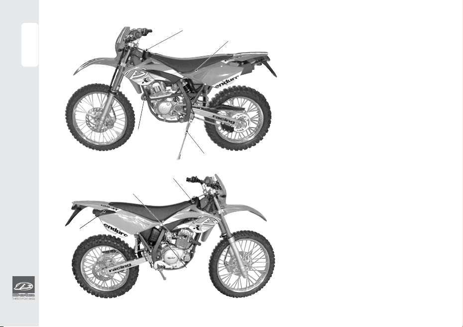
Main parts ........................................................... 6
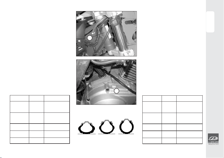
Vehicle identification data............................... 7
Tyres ..................................................................... 7
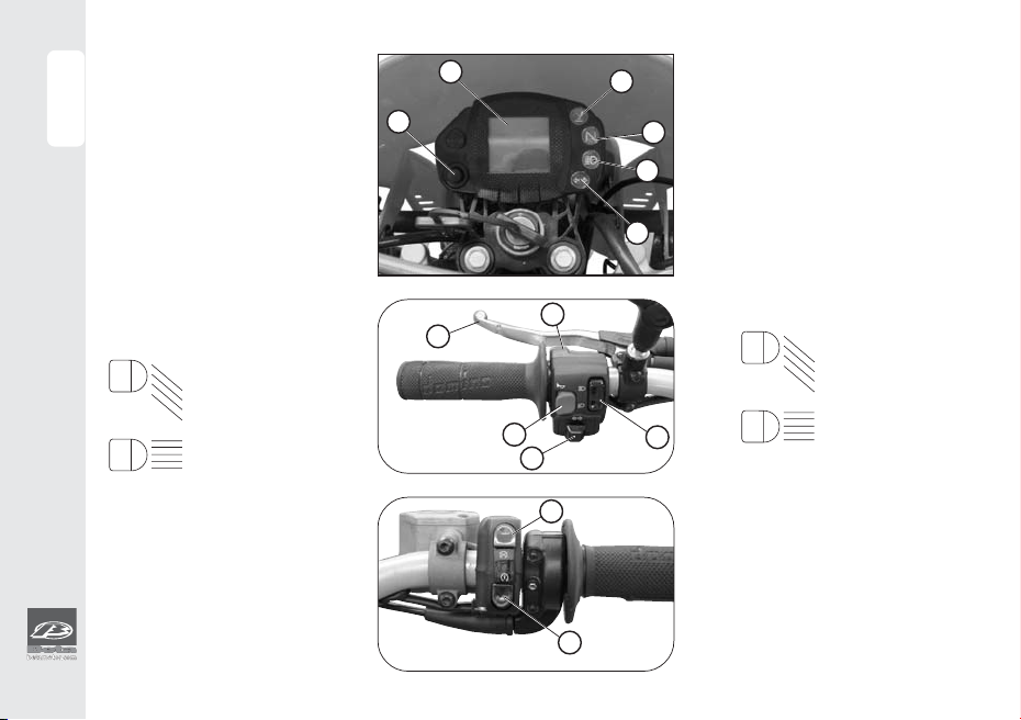
Hand drive controls ........................................... 8
LCD dispaly ......................................................... 9
Ignition switch ................................................... 18
Steering lock...................................................... 18
Technical data .................................................. 19
Recommended lubricants and liquids ........... 23
Electrical diagram ............................................ 24
Electrical devices .............................................. 26
SECTION 2 OPERATION AND USE
Checks and maintenance before
and after off-road use ...................................... 32
Fueling ................................................................33
Breaking in ......................................................... 34
Starting the engine ...........................................35
Sidestand ........................................................... 36
SECTION 3 MAINTENANCE AND CHECKS
Engine oil ............................................................ 38
Brake pump oil .................................................. 39
Removing the passenger seat and
the clearing air filter .......................................... 41
Spark plug .......................................................... 43
Front brake ........................................................ 44
Rear brake ......................................................... 45
Fume collecting pipe ....................................... 46
Removing the silencer ..................................... 41
Removing the plastics...................................... 48
Removing the fuel tank ................................... 48
Maintenance schedule ................................... 52
CAP.1 CONOSCENZA DEL VEICOLO
Elementi principali .............................................. 6
Dati identificazione veicolo .............................. 7
Pneumatici .......................................................... 7
Comandi.............................................................. 8
Indicazioni su LCD .............................................. 9
Commutatore ................................................... 18
Bloccasterzo ...................................................... 18
Dati tecnici ........................................................ 19
Lubrificanti e liquidi consigliati ........................ 23
Schema elettrico .............................................. 24
Dispositivi elettrici.............................................. 26
CAP.2 FUNZIONAMENTO E UTILIZZO
Controlli e manutenzione prima
e dopo l'utilizzo in fuoristrada.......................... 32
Rifornimento carburante ................................. 33
Rodaggio........................................................... 34
Avviamento del motore .................................. 35
Cavalletto laterale ........................................... 36
CAP.3 MANUTENZIONE E CONTROLLI
Olio motore ....................................................... 38
Olio pompa freni .............................................. 39
Rimozione sella passeggero
e pulizia filtro aria............................................. 41
Candela............................................................. 43
Freno anteriore ................................................. 44
Freno posteriore ................................................ 45
Tubo raccolta fumi ........................................... 46
Smontaggio marmitta...................................... 47
Rimozione delle plastiche ............................... 48
Smontaggio serbatoio carburante................. 49
Manutenzione programmata ......................... 52

INDICE
INDEX
4
CAP.4 REGOLAZIONI
Regolazione freni .............................................. 54
Regolazione frizione ......................................... 55
Regolazione minimo ........................................ 56
Regolazione gioco gas.................................... 56
Controllo e regolazione gioco sterzo ............ 57
Tensionamento catena ................................... 58
Regolazione ammortizzatore posteriore ....... 59
Regolazione fascio luminoso .......................... 60
CAP.5 SOSTITUZIONI
Sostituzione lampade faro anteriore ............. 62
Sostituzione lampade faro posteriore............ 64
Sostituzione indicatori di direzione.................... 65
CAP.6 COSA FARE IN CASO DI EMERGENZA
Ricerca del guasto ........................................... 68
INDICE ALFABETICO
Indice ................................................................. 71
SECTION 4 ADJUSTMENTS
Adjustment of brake ......................................... 54
Adjustment of clutch ........................................ 55
Adjustment of idling speed.............................. 56
Adjusting the throttle play ............................... 56
Check and adjustment of steering gear ....... 57
Tightening the chain......................................... 58
Adjustment of rear shock absorber ................ 59
Adjusting the headlight ................................... 60
SECTION 5 REPLACEMENTS
Replacing the headlight bulbs ....................... 62
Replacing the rear light bulbs ........................ 64
Replacing the indicators ................................. 65
SECTION 6 WHAT TO DO IN AN EMERGENCY
Trouble shooting ................................................ 68
ALPHABETICAL INDEX
Index ................................................................... 72
I dati e le caratteristiche indicate sul presente manuale non impegnano il costruttore che si riserva il diritto di
apportare modifiche ai propri modelli in qualsiasi momento.
The manifacturer reservs the right to change the data and features described in this manual and to modify
its products at any times.

5
1
GENERAL INFORMATION
CONOSCENZA DEL VEICOLO
CAPITOLO 1
SECTION 1
INDICE ARGOMENTI
Elementi principali
Dati identificazione veicolo
Comandi
Indicazioni su LCD
Commutatore
Bloccasterzo
Dati tecnici
Schema elettrico
Dispositivi elettrici
Lubrificanti e liquidi
consigliati
INDEX
Main parts
Vehicle identification data
Hand drive
LCD display
Ignition switch
Steering lock
Technical data
Electrical diagram
Electrical devices
Recommended lubricants
and liquids

6
1
GENERAL INFORMATION
CONOSCENZA DEL VEICOLO
MAIN PARTS
1Plug tank
2Air filter
3Stand
4Fuel tap
5Fuel tank
6Silencer
7Kick-starter
8Muffler
ELEMENTI PRINCIPALI
1Tappo serbatoio
2Filtro aria
3Cavalletto
4Rubinetto carburante
5Serbatoio carburante
6Silenziatore
7Kick-starter
8Marmitta
12
5
4
7
6
8
3

7
1
GENERAL INFORMATION
CONOSCENZA DEL VEICOLO
DATI IDENTIFICAZIONE VEICOLO
Identificazione telaio
Il codice identificazione telaio A è
impresso sul cannotto di sterzo nel
lato destro.
Identificazione motore
I dati di identificazione del motore B
sono impressi sul semicarter sinistro.
PNEUMATICI
Attenzione:
Per una guida sicura controllare fre-
quentemente i pneumatici.
•Mantenere la pressione dei pneu-
matici entro i limiti indicati.
•Effettuare il controllo della pressio-
ne ogni 15 giorni.
•Verificare la pressione solamente a
pneumatici freddi.
Enduro ant. post.
Dimensioni 80/90-21 o 110/80-18 corona z.52
90/90-21 120/90-18 corona z.54
Bar (fuori strada) 1 1
Bar (strada) 1,5 1,8
Motard ant. post.
Dimensioni 110/80-17 130/70-17
Bar 1,8 2
VEHICLE IDENTIFICATION DATA
Frame identification
Frame identification code Ais
stamped on the right side of the steer-
ing head tube.
Motor identification
Motor identification data Bare stamped
on the l.h. side half crankcase.
TYRE
Warning:
Foryourridingsafety, frequently check
the tyres.
•Keep the tyre pressures within the
prescribed range.
•Check the tyre pressures every other
week.
•Always measure the inflating
pressures when the tyres are cold.
B
A
Pressure is too low Pressureis
correct
Pressure is too
high
Pressione troppo
bassa
Pressione
giusta
Pressione troppo
alta
Enduro front rear
Size 80/90-21 or110/80-18 ring gear z.52
90/90-21 120/90-18 ring gear z.54
Bar (off-road) 1 1
Bar (road) 1,5 1,8
Motard front rear
Size 110/80-17 130/70-17
Bar 1,8 2

8
1
GENERAL INFORMATION
CONOSCENZA DEL VEICOLO
COMANDI
HAND DRIVE
1LCD
2Tasto MODE
3Spia indicatori direzione
4Spiaaccensione luciabba-
glianti
5Spia indicatore folle
6Spia cavalletto abbassato
7Leva comando frizione
8Pulsanteavvisatore acustico
9Commutatore luci
10 Pulsante abbaglianti
11 Pulsante indicatori di dire-
zione
12 Pulsante accensione
13 Pulsante stop motore
1LCD display
2MODE button
3Indicator warning light
4High beam warning light
5Neutral indicator
6Stand-down warning light
7Clutch lever
8Horn button
9Dip switch
10 High beam switch
11 Indicator switch
12 Start button
13 Engine stop button
= luci anabbaglianti
= luci abbaglianti
12
13
2
3
4
5
6
8
710
11 9
=
Low light
=High light
1

9
1
GENERAL INFORMATION
CONOSCENZA DEL VEICOLO
INDICAZIONI SU LCD
(funzionamento normale per utente)
Funzionamento e visualizzazione pagine e icone
•VELOCITÀ ISTANTANEA
•ODO Totalizzatore
•TRP Totalizzatore parziale
•CLK Orologio nei formati (hh:mm 23h 59mm)
•LAP Cronometro nei formati (mm:ss)
•SPEED max Velocità massima
•ICONA Batteria
•ICONA Ore cambio olio
•ICONA Benzina (non attiva)
•ICONA Chiave manutenzione
•ICONA Temperatura acqua.
•BARRA Per icone o per batteria (connessa di
default a batteria)
LCD DISPLAY
(Normal user operation)
Operation and display of pages and icons
• INSTANT SPEED
• ODO TOTAL COUNTER
• TRP TRIP COUNTER
• CLK CLOCK, FORMATS hh:mm / 23h, 59m
• LAP STOPWATCH, FORMAT mm:ss
• SPEED max MAXIMUM SPEED
• ICON BATTERY
• ICON HOURS TO OIL CHANGE
• ICON RESERVE FUEL
• ICON SERVICE SPANNER
• ICON WATER TEMPERATURE
• BAR FOR ICONS OR BATTERY (connected to
battery by default)

10
1
GENERAL INFORMATION
CONOSCENZA DEL VEICOLO
Successione pagine su LCD
Tutte le pagine a partire dalla pagi-
na di default sono raggiungibili solo
nella loro sequenza.
Verifica globale di tutti i segmenti e
di tutte le icone (fig. 1) presenti su
LCD e test sugli indicatori luminosi. Il
test dura 3 secondi.
Al termine del test si presenterà la
pagina di default.
La videata di default (fig. 2) si attiva
automaticamente dopo il TEST.
Visualizza:
Batteria - indica lo stato di carica
su barra verticale.
L’icona compare lampeggiante
solo all’esterno dei limiti impostati.
Velocità istantanea su digit grandi
(max 199 Km/h o Mph)
ODO totalizzatore dei Km o miglia
percorsi dalla prima inizializzazione.
Visualizzato su 5 digit piccoli 99999
Km o miglia.
Parametro non azzerabile.
Fig. 1
Fig. 2
Order of pages on LCD display
The different pages can only be
viewed in succession from the de-
fault
General check of all the icons (fig.
1) and bars on the LCD display and
indicator light test. The test lasts 3
seconds.
At the end of the test the default
page will be displayed.
The default page (fig. 2) is automati-
cally displayed at the end of the
test.
Displayed information:
Battery - Shows the battery charge
on a vertical bar.
The icon blinks only when the
charge is outside the set limits.
Instant speed on large digits (max.
199 Km/h or Mph)
ODO Total counter measuring the
kilometres or miles covered from the
initial setup. Displayed on 5 small dig-
its (99999 Km or mi).
The parameter cannot be reset.

11
1
GENERAL INFORMATION
CONOSCENZA DEL VEICOLO
Dalla figura 2 premendo brevemen-
te MODE a mezzo fermo si passa
alla figura 3.
Il passaggio avviene al rilascio del
comando.
Visualizza:
Velocità istantanea su digit grandi
(max 199 Km/h o Mph)
TRP Totalizzatore parziale visualizzata
su 4 digit piccoli (max 999.9 Km o
Miglia)
Azzerabile manualmente o auto-
maticamente al raggiungimento
dei 999.9 Km o miglia.
Dalla figura 3 premendo brevemen-
te MODE a mezzo fermo si passa
alla figura 4
Il passaggio avviene al rilascio del
comando.
Visualizza:
Velocità istantanea su digit grandi
(max 199 Km/h o Mph)
Orologio ORE:MINUTI su digit picco-
li, 00:00
Regolabile tramite MODE a mezzo
fermo come di seguito descritto.
Fig. 3
Fig. 4
To bring up the screen shown in Figure
2, press the MODE button for a short
time while the screen in Figure 3 is dis-
played and the vehicle is stationary.
The new screen is displayed as soon
as the button is released.
Displayed information:
Instant speed on large digits (max.
199 Km/h or Mph)
TRP Trip counter, displayed on 4 small
digits (max. 999.9 Km or mi)
The counter can be reset manually
or automatically when 999.9 Km or
mi are totalled.
Pressing the MODE button for a short
time while the screen is as shown in
Figure 3 brings up the screen shown
in Figure 4.
The new screen is displayed as soon
as the button is released.
Displayed information:
Instant speed on large digits (max.
199 Km/h or Mph)
Clock HOURS:MINUTES on small dig-
its, 00:00
The time is set through the MODE but-
ton while the vehicle is stationary by
using the procedure detailed below.

12
1
GENERAL INFORMATION
CONOSCENZA DEL VEICOLO
Procedurad’impostazionedell’orologio
1°-PremereMODEfino allampeggio
dei numeri relativi alle ore.
2°- Rilasciandolo e ripremendolo: le
oreavanzanodiunnumero.Man-
tenendolo premuto avanzano
automaticamente. Lasciandolo
inattivo si passa al punto 4°.
3°-Rilasciare il pulsante MODE a ore
raggiunte.
4°-Dopo 2” lampeggiano i minuti.
5°-Operare come al punto 2°. La-
sciando MODE inattivo si passa
al punto 6°.
6°-Rilasciare il pulsante MODE a mi-
nuti raggiunti e dopo 2” l’orario
verrà assunto.
Clock setting procedure
1. Press the MODE button until the
hour digits start blinking.
2. Releasing the button and then
pressing it again increases the
hours by one unit. Holding down
the button causes the figures to
changerapidly. Leavingthe but-
ton inactive skips to step 4.
3. Release the MODE button when
thecorrecthour settinghas been
obtained.
4. After 2 seconds the minute digits
start blinking.
5.Repeat theprocedure described
at step 2. Leaving the MODE but-
ton inactive skips to step 6.
6. Release the MODE button when
the correct minute setting has
been obtained.
Fig. 4

13
1
GENERAL INFORMATION
CONOSCENZA DEL VEICOLO
Dallafigura4premendobrevemen-
te MODE si passa alla figura 5. Il
passaggio avviene al rilascio del
comando.
Visualizza:
Velocità istantanea su digit grandi
(max 199 Km/h o Mph)
Premendoli per un tempo maggio-
re di 1” si attiva il cronometro pas-
sando alla figura 6 dove comparirà
al posto delle barrette l’indicazione
del cronometro nella forma
MINUTI:SECONDI00:00,visualizzati su
4 digit piccoli.
Fig. 5
To bring up the screen shown in Fig-
ure 4, press the MODE button for a
short time while the screen shown
in Figure 5 is displayed. The new
screen is displayed as soon as the
button is released.
Displayed information:
Instant speed on large digits (max.
199 Km/h or Mph)
Pressing them for more than 1 second
activates the stopwatch (Figure 6),
where the bars are replaced by the
time in the format MINUTES:SECONDS
00:00 on 4 small digits.

14
1
GENERAL INFORMATION
CONOSCENZA DEL VEICOLO
Fig. 6
Per il passaggio alla pagina succes-
siva occorre disattivare la figura 5.
La disattivazione avviene a due livelli:
1°- Mantenendo cronometro in fun-
zione. Premere MODEda figura 6
per un tempo compreso fra 1 e 2
secondifino alla ricomparsa del-
lafigura 5. Rilasciare il comando.
Ripremendo MODE brevemente
sipassaallafigura7.Il cronometro
resta in funzione indicato da LAP
che lampeggia.
2°- Arrestando il cronometro. Pre-
mere MODE da figura 6 per un
tempo superiore ai 2 secondi, si
evidenzierà prima la figura 5, poi
ancora la figura 6 con indicato il
tempo segnato dal cronometro.
Al rilascio il cronometro viene az-
zerato e fermato. Premendo
MODE per un tempo da 1 a 2
secondi ricompare la figura 5.
Ripremendo MODE brevemente
si passa alla figura 7.
To skip to the next page, one must
first exit the screen shown in by fol-
lowing either of these procedures:
1°-While the stopwatch is running. Press
MODE (Figure 6) for 1 to 2 seconds
until the screen shown in Figure 5 is
displayed, then release the button.
Pressing MODE again for a short
time brings up the screen shown in
Figure 7. LAP blinks to denote that
the stopwatch is still running.
2°-After stopping the stopwatch.
Pressing MODE for more than 2
seconds while the screen shown
in Figure 6 is displayed first brings
up the screen shown in Figure 5
and then the screen shown in Fig-
ure 6, displaying the time re-
corded by the stopwatch. When
the button is released, the stop-
watch is reset and stopped. Press-
ing MODE for 1 to 2 seconds
brings up the screen shown in Fig-
ure 5 again. Pressing MODE for a
short time brings up the screen
shown in Figure 7.

15
1
GENERAL INFORMATION
CONOSCENZA DEL VEICOLO
Con cronometro in funzione l’atti-
vazione del conteggio avviene
come segue:
- attivazione e arresto manuale
MODE con impulso breve.
- attivazione e arresto in automati-
co da impulso ruota. Dopo 3 se-
condi dall’arresto ruota il
cronometro cesserà di misurare,
correggendo il tempo di ritardo.
L’arresto del conteggio avviene
sempre con arresto moto, anche se
l’attivazione era stata fatta da co-
mando manuale.
Su questa figura (fig. 6) compare il
cronometro con il tempo trascorso
se in precedenza era attivo, o tutto
a zero se era inattivo.
Dalla figura 5 premendo brevemente
MODE a mezzo fermo si passa alla
figura 7. Il passaggio avviene al rila-
scio del comando.
Visualizza:
Velocità istantanea su digit piccoli
(max 199 Km/h o Mph)
SPEEDmaxVelocitàmassimaraggiun-
ta dall’ultimo azzeramento. E’
evidenziata da Km/h lampeggiante.
Azzerabile manualmente.
When the stopwatch is running, the
count is started as follows:
-Manual start/stop obtained by
briefly pressing the MODE button.
-Automatic start/stop from wheel
pulse. Three seconds after the
wheel has come to a halt, the stop-
watch ceases to operate and the
delay is compensated for.
The count is stopped when the ve-
hicle comes to a halt even if it had
previously been started manually.
shows the stopwatch displaying the
elapsed time if the stopwatch was run-
ning or set to zero if it was inactive.
To bring up the screen shown in Fig-
ure 7, press the MODE button for a
short time while the screen in Figure
5 is displayed and the vehicle is sta-
tionary. The new screen is displayed
as soon as the button is released.
Displayed information:
Instant speed on small digits (max.
199 Km/h or Mph)
SPEED max Maximum speed
reached by the vehicle from the last
time the parameter was reset. It is
denoted by a blinking Km/h.
It can be reset manually.
Fig. 7

16
1
GENERAL INFORMATION
CONOSCENZA DEL VEICOLO
Oscuramento delle videata
Se qualche videata può essere ritenuta non utile la si può rende-
re invisibile, pur restando sempre attiva, per accelerare il
raggiungimento della videata successiva può essere oscurata.
Tutte le videate, sia in blocco che singolarmente, ad esclusione
della figura/videata 17 di default, possono essere oscurate.
Per disattivare una videata, premere MODE dalla videata che
si vuol oscurare e mantenerlo premuto. Alla scomparsa dei
valori relativi alla stessa, accendere e spegnere 5 volte il faro
abbagliante sempre con pulsante premuto.
Al rilascio del pulsante la videata non è più visibile.
Per riattivare le videate, premere MODE dalla videata ODO.
Alla scomparsa dei valori relativi alla stessa, accendere e spe-
gnere 5 volte il faro abbagliante sempre con pulsante pre-
muto. Le pagine oscurate si riattiveranno tutte.
Se nessuna pagina era oscurata si oscureranno tutte.
Per riattivarle ripetere l’operazione.
Cancellazione parametri TRP, SPEED max, LAP
I parametri cancellabili sono:
- Percorso indicato da TRP
- SPEED max velocità massima raggiunta
Tempi indicati da LAP
La cancellazione dei parametri è attuabile con MODE a mezzo
fermo.
Cancellazione TRP e SPEED max
Premere MODE in presenza della grandezza che si vuol azze-
rare fino alla comparsa in sostituzione del numero delle “- - -
-”, al rilascio il numero si presenterà 0.0.
Cancellazione LAB
L’azzeramento del tempo di LAB avviene dalla figura 21 te-
nendo premuto MODE per un tempo sufficiente a visualizzare
prima la figura 20 e poi nuovamente la figura 21. Al rilascio il
valore verrà azzerato.
Blanking out screens
If a screen is believed to be of no interest, it can be blanked
out without deactivating it so as to speed up the display of
the next page.
All the pages can be blanked out, individually or in sets, with
the exception of the default screen shown in Figure 2.
To blank out a screen, hold down the MODE button while dis-
playing the screen in question. When the screen goes out, switch
the high beam on and off five times while still holding the button
depressed.
When the button is released, the page will no longer be visible.
To make the screens visible again, press MODE while the ODO
screen is displayed. When the screen goes out, switch the high
beam on and off five times while still holding the button depressed.
All blanked-out pages will become visible again. If no page had
been previously hidden, all pages will be blanked out.
To display the pages again, repeat the above procedure.
Resetting the LAB. Speed max, TRP parameter
The following parameters can be reset:
- TRP, trip counter
- SPEED max maximum speed
LAP times
The parameters can be reset by pressing the mode button
while the vehicle is stationary
Resetting the TRP e SPEED max parameters
Press MODEwhile the parameters to be reset is displayed until
“——” replaces the figures. Wehen the button is released, “0.0”
will be displayed.
Resetting the LAB parameter
To reset the LAB time, hold down the MODE button while the
screen shown in Figure 6 is displayed until the screens shown
in Figures 5 and 6 are shown in succession. The parameter will
be reset as soon as the button is released.

17
1
GENERAL INFORMATION
CONOSCENZA DEL VEICOLO
Icone di servizio (figura 8)
Le icone di servizio si attiveranno
automaticamente al raggiungi-
mento del 90% del valore imposta-
to.
Si presenteranno su tutte le pagine,
prima fisse e al superamento del
valore impostato lampeggianti.
LeiconeTemperatura acquae Ben-
zina si presenteranno solo se saran-
no collegati allo strumento i rispetti-
vi trasduttori OFF-ON. Fig. 8
IService icons (figure 8)
The service icons are automatically
activated as soon as 90 per cent of
the set value is reached. The icons
will be displayed on all pages, ini-
tially fixed and then, when the set
value is exceeded, blinking.
The Water Temperature and Re-
serve Fuel icons will only be dis-
played if the related OFF-ON trans-
ducers are connected to the instru-
ment.

18
1
GENERAL INFORMATION
CONOSCENZA DEL VEICOLO
Fig. 9
ICONA BATTERIA Vb FUORI DAI LIMI-
TI IMPOSTATI
Il lampeggio della prima barra verti-
cale e della batteria indica che la
tensione del generatore, per moto
senza batteria, o della batteria è mi-
nore del limite minimo impostato.
Se la segnalazione persiste occorre
verificarne la causa.
Il lampeggio di tutte le barre e del-
la batteria indica tensione del ge-
neratore o della batteria superiore
al limite massimo impostato.
ATTENZIONE. Se lo strumento è mu-
nito di pila interna per il comando
dell’orologio, quindi destinato a
moto prive di batteria, la stessa pre-
senterà un’autonomia di 3 anni
dalla consegna operata da con-
cessionario BETA.
Quando la batteria sarà esaurita
l’orologio non manterrà
l’impostazione se il motore del vei-
colo verrà spento (cioe’ quando la
tensione di alimentazione principa-
le viene a mancare). Andrà sostitu-
ita seguendo le istruzioni riportate sul
disegno dello strumento.
BATTERY ICON Vb OUTSIDE SET LIMITS
The blinking of the first vertical bar
and the battery icon denotes that
the voltage of the battery, or the
generator if the vehicle has no bat-
tery, is less than the set limit. If the
indication persists, the cause will
have to be determined.
When all the bars and the battery
icon are blinking, the voltage of the
battery or the generator exceeds
the maximum limit.
IMPORTANT: For vehicles not
equipped with a battery, the life of
the clock battery in the instrument
panel is 3 years from the time of
delivery by the BETA dealer.
A flat battery does not allow the
clock to retain the time setting when
the engine is switched off (i.e. when
power is no longer supplied). To re-
place the battery, follow the steps
shown on the instrument panel.

19
1
GENERAL INFORMATION
CONOSCENZA DEL VEICOLO
Il veicolo è dotato di quattro chiavi
multiuso (e delle relative scorte) da
utilizzarsi per il commutatore e per il
bloccasterzo.
Attenzione: non tenere le chiavi di
scortanella moto, madepositarlein
un luogo sicuro.
Le suggeriamo di annotarsi il nume-
ro di codice impresso nelle chiave,
per poter eventualmente richieder-
ne un duplicato.
COMMUTATORE
Controlla il circuito di accensione
OFF: Sistema elettrico disattivato
ON: Si può effettuare l'accensio
ne del veicolo.
BLOCCASTERZO
A: Il bloccasterzo è disinserito
B: Il bloccasterzo è inserito
Per l'inserimento del bloccasterzo
occorre sterzare il manubrio a sini-
stra, premere sulla chiave, ruotarla
completamente in senso antiorario
e dopo rilasciarla.
The vehicle is supplied with four keys
(with related spares) to be used for
the ignition switch and the steering
lock.
Warning: Do not keep the spare key
inside the wehicle, but in a safe
place. We suggest you note the
code number stamped on the keys.
In this way you can obtain a dupli-
cate.
IGNITION SWITCH
Controls the ignition circuit
OFF: Electrical system is discon-
nected
ON: Engine can be started.
STEERING LOCK
AThe steering lock is off
BThe steering lock is on.
To engage the steering lock, turn
the handlebars to the left, push in
the key, turn it all the way anticlock-
wise and then release it.
A
B
OFF
ON
This manual suits for next models
1
Table of contents
Other Beta Motorcycle manuals

Beta
Beta Ark AC User manual

Beta
Beta Minicross R 10 User manual

Beta
Beta RR 4T ENDURO 2014 350 Guide

Beta
Beta Evo4t 300 User manual

Beta
Beta RR 2T 2013 User manual

Beta
Beta RR 4T-400 Instruction manual

Beta
Beta RR4T USA 400 User manual

Beta
Beta Motard M4 User manual

Beta
Beta 350-498 RR User guide

Beta
Beta MINITRIAL 50 User manual