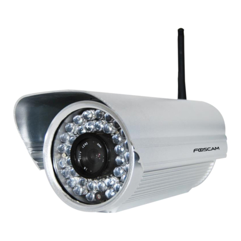
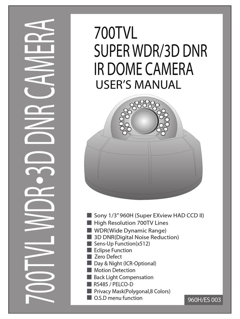
Beward N6603 User manual

IR LEDs built in

Table of contents
N6603 Installation User Manual
1
Table of contents
CHAPTER 1. SAFETY WARNINGS ................................................................................................................... 2
CHAPTER 2. OVERVIEW................................................................................................................................... 4
2.1. FEATURES ................................................................................................................................................ 4
2.2. SPECIFICATIONS ....................................................................................................................................... 5
2.3. PACKAGE CONTENTS ................................................................................................................................ 6
CHAPTER 3. PHYSICAL DESCRIPTION .......................................................................................................... 7
3.1. SIDE PANEL.............................................................................................................................................. 7
3.2. FRONT PANEL......................................................................................................................................... 10
CHAPTER 4. INSTALLING THE CAMERA AND CONNECTING A CABLE....................................................11
4.1. OVERVIEW OF CONNECTING THE N6603 TO A NETWORK............................................................................11
4.1.1. Connecting the Camera Using PoE Technology ...........................................................................11
4.1.2. Connecting the Camera via Power Connector ..............................................................................11
4.2. INSTALLATION RECOMMENDATIONS .......................................................................................................... 12
4.3. INSTALLING THE CAMERA......................................................................................................................... 13
4.3.1. Attaching the Sunshield ................................................................................................................ 13
4.3.2. Mounting the Camera ................................................................................................................... 14
4.4.WIRED CONNECTION TOA NETWORK ....................................................................................................... 15
4.5. CONNECTING THE ALARM CONTACTS....................................................................................................... 16
CHAPTER 5. SETTING UP THE WIRED CONNECTION FOR WINDOWS 7................................................. 18
5.1. DEFINING THE LOCAL NETWORK PARAMETERS ......................................................................................... 18
5.1.1. Defining the Local Network Parameters When Using a Dynamic IP Address.............................. 22
5.2. CHANGING THE LOCAL NETWORK PARAMETERS ....................................................................................... 25
5.3.ACCESSING THE IPCAMERA.................................................................................................................... 29
5.3.1. Installing “BEWARD IP Installer” Software ................................................................................... 29
5.3.2. Accessing the IP Camera Using “BEWARD IP Installer” Software ............................................... 29
5.3.3. Accessing the IP Camera Using the Network Menu in Windows 7 .............................................. 31
5.3.4. Accessing the IP Camera Using Internet Explorer........................................................................ 32
5.4.ACCESSING THE WEB INTERFACE............................................................................................................. 32
5.5. CONFIGURING THE CAMERA’S NETWORK SETTINGS THROUGH THE WEB INTERFACE................................... 35
5.6. RESTORING THE NETWORK SETTINGS OF THE COMPUTER TO THEIR PREVIOUS VALUES............................. 38
5.7. VERIFYING THE CONNECTION SETTINGS................................................................................................... 42
CHAPTER 6. ACCESSING THE CAMERA OVER THE INTERNET ............................................................... 44
6.1. OVERVIEW OF INTERNETACCESS TO THE CAMERA ................................................................................... 44
6.2. USING AN EXTERNAL STATIC IPADDRESS OR PPPOECONNECTION.......................................................... 44
6.2.1. Using an External Static IP Address............................................................................................. 44
6.2.2. Using a PPPoE Connection.......................................................................................................... 45
6.3. INTERNETACCESS TO THE CAMERA ON A LOCAL NETWORK....................................................................... 47
6.3.1. Using the UPnP Option................................................................................................................. 47
6.3.2. Manual Port Forwarding................................................................................................................ 49
6.4.ACCESSING THE CAMERA OVER THE INTERNET USING DYNDNS SERVICE .................................................. 54
6.4.1. Overview of Internet Access to Cameras Using DynDNS service................................................ 54
6.4.2. Creating an Account at DynDNS Service ..................................................................................... 54
6.4.3. Creating a Domain Name at DynDNS .......................................................................................... 58
6.4.4. Setting up the Equipment to Work with DynDNS.......................................................................... 62
APPENDIX ........................................................................................................................................................ 66
APPENDIXA. PORT VALUES............................................................................................................................ 66
APPENDIX B. FACTORY DEFAULTS................................................................................................................... 67
APPENDIX C. GLOSSARY................................................................................................................................ 68

Chapter 1. Safety Warnings
N6603 Installation User Manual
2
Chapter 1. Safety Warnings
Before using this product
This camera complies with all safety rules. However, improper use of this camera may
cause fire resulting in body injury and property damage as well. Before you start to use this
camera, please read and thoroughly understand the instructions in this user manual.
IMPORTANT!
Use only accessories recommended by the manufacturer. The use of improper accessories may cause
hazards.
Follow the operating instructions
Do not use and store this camera in dangerous environments:
Do not expose to extremely low or high temperatures (camera’s operating temperature is
-65 to +50°C)
Do not expose to direct sunlight and do not install near any heat resources
Do not install near water sources
Avoid electromagnetic interference
Do not expose to vibration
IMPORTANT!
If you experience problems with this camera, please contact your local dealer for assistance.
In case if:
You notice a strange smell or smoke
Any liquid has been spilled or objects have fallen into this camera
This camera has been dropped or damaged
Do the following:
Unplug the power cord and disconnect all cords from the camera
Contact our Service Center. You can find contact information on our website:
http://www.beward.eu/.
Transportation
If you need to transport this camera, carefully repack it using the original box and attach
protective materials.

Chapter 1. Safety Warnings
N6603 Installation User Manual
3
Ventilation
Keep good ventilation in the area where the camera is installed to prevent its overheating.
Cleaning
To clean external components, use a soft, dry cloth. To remove persistent dirt, use some
detergent and a soft cloth.
Do not use volatile cleaners, alcohol, benzene or other harsh solvents.

Chapter 2. Overview
N6603 Installation User Manual
4
Chapter 2. Overview
BEWARD N6603 is designed for both indoor and outdoor usage. The camera’s housing
surely protects it against harsh weather conditions and is IP66 rated, so that the camera can be
used in any environmental conditions.
The N6603 features a progressive scan CMOS sensor and a mechanical IR cut filter, which
ensures clear pictures under low-light conditions. Besides, the camera has built-in IR LEDs, which
provide twenty-four-hour surveillance.
Pic. 2.1
2.1. Features
IP66 rated housing
Motorized IR cut filter
15 meter IR distance
Optimal solution concerning price/quality
Recording to network attached storage (NAS)
Professional surveillance software included (16 channels)
Simultaneous streaming: MPEG-4/MJPEG
Two-way audio, support for connecting an external microphone

Chapter 2. Overview
N6603 Installation User Manual
5
Viewing camera images on a mobile phone (including iPhone)
Built-in multi-zone motion detection
Sending of images and video via e-mail and to FTP
PoE IEEE 802.3af Class 0 support
2.2. Specifications
Compact size (80 хØ102 mm (with sunshield: 116/145 mm), weight is 635 g)
Sensor: 1/4'' progressive scan CMOS
Built-in lens: M12, f4.0 mm, F1.5 (angle of view: 65°diagonal, 53°horizontal, 40°
vertical)
Motorized IR cut filter
Sensitivity: 0.5 lux @ F2.0 (0 lux if IR LED is on)
Shutter time: 1/7.5 ~ 1/120 sec
Illumination: IR LED (850 nm), 21 pcs, 8 mm diameter, up to 10-15 meters
S/N ratio: 50 dB
Resolution: 640х480, 320х240, 160х120
Simultaneous streaming: Motion JPEG, MPEG-4 part 2 (ISO/IEC 14496-2) Profile: SP,
3GPP
Frame rate: MPEG-4: up to 30 frames per second at all resolutions; Motion JPEG: up to
15 frames per second at all resolutions; 3GPP: up to 10 frames per second at 320х240,
160х120
Digital zoom: 10x
Two-way audio, 3.5 mm jack, output for connection of an external microphone and
speakers
Built-in multi-zone motion detection, sensitivity and threshold control
Up to 5 simultaneous connections
Continuous, scheduled and motion detection triggered sending of images and video via
e-mail and to FTP
Power: 12 V DC, 1 A (DC), 12 W maximum, PoE IEEE 802.3af Class 0
Operating temperature: -65 to +50°С
Supported protocols: Bonjour, TCP/IP, DHCP, PPPoE, ARP, ICMP, FTP, SMTP, NTP,
UPnP, RTSP, RTP, HTTP, TCP, UDP, 3GPP/ISMA RTSP
Support for ONVIF v1.02

Chapter 2. Overview
N6603 Installation User Manual
6
2.3. Package Contents
IP camera N6603 (lens M12, 4.0 mm, F1.5 pre-installed)
Sunshield
RJ-45 adapter
Quick installation guide
CD with user manuals and software
Bracket
Power supply 12 V 1 A DC

Chapter 3. Physical Description
N6603 Installation User Manual
7
Chapter 3. Physical Description
3.1. Side Panel
Pic. 3.1
Camera’s housing consists of a base and a cover.
Base: this part of housing contains hardware components of the camera. The sunshield
and the bracket are attached to the base.
Cover: this part of housing protects the camera lens and IR LEDs against physical and
environment influence. The cover is screwed onto the base using a threaded connection.
NOTE:
The transparent part of the cover is a part of the camera’s optical system. To prevent scratching, please
do not touch the transparent part.
IMPORTANT!
The cover is screwed onto the base by the manufacturer under special conditions that provide for housing
tightness. If unscrewing the cover, you should take notice of the tightness and humidity. The camera must
be assembled in a dry atmosphere in humidity conditions that are lower than 20 –30%. Otherwise it may
cause condensation on the camera front cover glass.

Chapter 3. Physical Description
N6603 Installation User Manual
8
Sunshield: protects the camera lens against direct sunlight.
Bracket: allows mounting the camera on a surface (e.g. a ceiling, a wall, etc).
Connecting cable: one end of this cable is plugged into the camera, the other end of this
cable contains the following connectors:
IMPORTANT!
Unscrewing of the connecting cable from the base is PROHIBITED! Non-compliance with this requirement
will void your warranty.
Network connector: use this port to connect to an Ethernet LAN using an RJ45 connection
(for user’s convenience, an RJ-45 adapter is included with the N6603). Besides, this camera can
be supplied with power over a twisted pair cable (PoE technology) with the use of special
equipment (such as a PoE injector).
Power connector: connects the camera to 12 V DC 1 A power.
IMPORTANT!
Simultaneous power supply over PoE and power connector is prohibited!
Audio in: a line in for an external microphone.
Reset button: when the camera is on, press this button to reboot the camera. Press and
hold this button for at least 10 seconds to reset the camera to factory settings. If a user holds this
button during less than 10 seconds, the camera will reboot without reset to factory settings.
NOTE:
The reset button is covered with a special cap with a hole to protect the button against accidental use.
Slightly push it for activation.
Audio out: a line out for external speakers (e.g. earphones or speakers with a built-in
amplifier).
Terminal block: an alarm input and output.
The table below provides a description and specifications of the connectors.

Chapter 3. Physical Description
N6603 Installation User Manual
9
Connector
Picture
Description
Network connector
RJ-45 connector.
RJ-45 adapter is included.
Power connector
Power connector (socket).
Provides for the connection
of a 12 V 1 A power
adapter.
Audio in / Audio out
Soldering of the connector for audio
in/audio out
TRS connector (socket) 3.5
mm mini jack.
1 –left channel
2 –right channel
3 –general purpose
Reset button
Slightly push this button to
reset the camera to factory
defaults or to reboot it.
Never use sharp objects to
press it.
Terminal block
No: output contact (external
alarm device)
Com: output contact –12 V
DI-: input contact –GND
DI+: input contact –12 V
For information about how
to connect the terminal
block, refer to paragraph
4.5.

Chapter 3. Physical Description
N6603 Installation User Manual
10
3.2. Front Panel
Pic. 3.2
Lens: built-in lens: M12, f4.0 mm, F1.5 (angle of view: 65° diagonal, 53°horizontal, 40°
vertical).
IR LED: 850 nm, 21 pcs, 8 mm diameter. 15 meter IR distance. Besides, IR illumination is
invisible to the human eye.
NOTE:
The LEDs are red when the IR illumination is on.

Chapter 4. Installing the Camera and Connecting a Cable
N6603 Installation User Manual
11
Chapter 4. Installing the Camera and Connecting a Cable
4.1. Overview of Connecting the N6603 to a Network
BEWARD N6603 IP camera can be powered over a twisted pair cable thanks to support for
PoE technology. Therefore, it provides two ways to deliver power to the camera:
Over a twisted pair cable using PoE technology.
Through the camera’s power cord socket using the supplied power adapter.
IMPORTANT!
Simultaneous power supply over PoE and the camera’s power cord socket is prohibited!
4.1.1. Connecting the Camera Using PoE Technology
This camera can be connected to a network using a PoE injector. The Picture 4.1 shows a
switch with PoE support. Such a switch may have standard data outputs as well as several PoE
outputs, which can be used both for data transfer and power supply.
Pic. 4.1
4.1.2. Connecting the Camera via Power Connector
Connect the N6603 to an Ethernet network. Power is delivered through the power supply
that is included with this camera or similar, compatible with it.
Pic. 4.2

Chapter 4. Installing the Camera and Connecting a Cable
N6603 Installation User Manual
12
IMPORTANT!
Use only the power supply that is included with the N6603 camera or a compatible power supply that
meets the following requirements: DC voltage of 12 V, current strength of 1 A.
4.2. Installation Recommendations
This section provides recommendations that should be observed when mounting and
installing the N6603.
Tips on camera placement:
This camera is designed for both indoor and outdoor surveillance. The operating
temperature is down to -65 and up to +50°С.
It is recommended to put the connectors inside a junction box (not supplied) to protect
them against environmental hazards.
Do not expose this camera to direct sunlight for a long period of time. Do not install it
near any heat resources.
Incorrect installation may cause undesirable “blind spots” that are not visible to the
security operator.
Do not install this camera near water sources.
Avoid electromagnetic interference.
When installing the camera, take notice of possibility of laying connecting cables.
Avoid unstable installation, which may cause vibration. This, in turn, may reduce motion
detection performance and image crispness.
Surveillance cameras should be installed so that they are inaccessible to unauthorized
persons and protected enough against damage and changing of viewing direction.
When installing the camera, you should clearly determine the viewing direction.
Tips on twisted pair cable installation:
In corridors, electric and feeble-current cables should be installed in different conduits
that are disposed on different walls.
Twisted pair and electric cables can be installed in the same conduit using different
sections of the cable that have solid longitudinal partitions with at least 0.25 h of fire
resistance, which are made of non-combustible material and should be positioned in
work areas at distance of 15 meters maximum if the electrical power does not exceed 5
kW.
Electric and feeble-current cables should be placed in parallel to each other at distance
of at least 50 mm in different conduits or different sections of conduit. If the electric field

Chapter 4. Installing the Camera and Connecting a Cable
N6603 Installation User Manual
13
strength from the electric cables exceeds 3 V/m, you should increase the distance
between the electric and feeble-current cables or reduce the electromagnetic noise.
Twisted pair and electric cables should cross each other at right angles.
Unshielded twisted pair cables should be located at distance of at least 125 mm from
fluorescent gas-discharge lamps or from other high-voltage discharge devices.
Unshielded twisted pair cables should be located at distance of at least 1.5 meters from
electromagnetic interference sources that produce electric field strength exceeding 3
V/m.
Switchboards with pinned unshielded twisted pair cables should be located at distance
of at least 3 meters from electromagnetic interference sources that produce electric field
strength exceeding 3 V/m.
Entire twisted pair cables should be arranged between the points of connection so the
cable run is as short as possible.
Minimum cable bending radius is four times the cable diameter (or 1 inch=2.5 cm) or it is
also acceptable to install the cable so the cable bending radius is 2 inches (5 cm).
Maximum length of the entire segment is 100 meters.
4.3. Installing the Camera
4.3.1. Attaching the Sunshield
If necessary, you can attach the sunshield to the camera. It is fastened with two screws,
which are included with this camera.
Step 1: fasten the sunshield with two screws. To prevent damaging of the sunshield, insert
the supplied plastic washers between the sunshield and the screw head. Adjust the sunshield so it
can easily slide in forward and backward direction.
Step 2: slide the sunshield to the desired position (Pic. 4.3).
Pic. 4.3

Chapter 4. Installing the Camera and Connecting a Cable
N6603 Installation User Manual
14
Step 3: secure the sunshield with the screws.
4.3.2. Mounting the Camera
The bracket is attached to the surface using 3 self-tapping screws (25x6) (Pic. 4.4).
Step 1: mark the location of the holes that you are going to drill to attach the bracket.
Step 2: drill three holes of 25 mm depth into the surface if you use the supplied screws.
Step 3: attach the bracket to the surface using the three self-tapping screws.
Pic. 4.4
The bracket is attached to the camera by twisting it (using the screw connection in the top
part of the bracket) in the special holes located in the top and bottom parts of the base. Tilt the
camera to the desired position using the two adjustment handles (Pic. 4.5).
Pic. 4.5
NOTE:
The bracket screw holes are compatible with the sunshield attachment holes. Therefore, you can use the
sunshield attachment holes to attach the bracket as well.

Chapter 4. Installing the Camera and Connecting a Cable
N6603 Installation User Manual
15
Step 4: put the connectors inside a junction box. The junction box must be protected
enough to prevent water getting inside it.
IMPORTANT!
A junction box is not supplied with the N6603 and you need to purchase it separately. Recommended
dimensions are 100х100х50.
4.4. Wired Connection to a Network
Step 1: provide power to the camera using either of the following ways (see paragraph 4.1):
Over a twisted pair cable using PoE technology.
Through the camera’s power cord socket using the supplied power adapter.
IMPORTANT!
Simultaneous power supply over PoE and the power connector is prohibited!
IMPORTANT!
Use only the power supply that is included with the N6603 camera or a compatible power supply that
meets the following requirements: DC voltage of 12 V, current strength of 1 A.
Step 2: use an RJ45 network cable to connect the camera to a network.
If needed, you can purchase a network cable separately or if you have the materials, tools
and skills, you can make a network cable.
A straight RJ-45 cable (UTP category 5)
The table below shows an example of a patch cord to connect the camera to a computer or
a network switch.
One end
Other end
1: White and orange
1: White and orange
2: Orange
2: Orange
3: White and green
3: White and green
4: Blue
4: Blue
5: White and blue
5: White and blue
6: Green
6: Green
7: White and brown
7: White and brown
8: Brown
8: Brown

Chapter 4. Installing the Camera and Connecting a Cable
N6603 Installation User Manual
16
To make a network cable, you need the following materials: a UTP category 5 cable, two
RJ-45 connectors and an RJ-45 crimping tool.
Assembling the pairs of wires in the correct order (see the table above) ensures data
transfer speed of 100 Mbps.
4.5. Connecting the Alarm Contacts
BEWARD N6603 IP camera has an alarm input and an alarm output, which can be used to
connect an external alarm device or a sensor.
Alarm input: use it to connect external sensors. An alarm is generated when the input
voltage reaches a certain value (specified in the camera parameters).
Alarm output: use it to connect alarm devices (e.g. a signal device). When an alarm
event occurs, it changes the output voltage to a certain value (specified in the camera
parameters).
NOTE:
If you use external sensors, be aware that the camera has logical I/O and exceeding the rated voltage and
current (max 30 W and 12 V) is PROHIBITED!
There are two I/O voltage levels for the N6603 IP camera:
High: voltage level is 12 V.
Low: voltage level is 0 V.
The camera’s relay triggers when the output voltage reaches a certain level. Depending on
the selected voltage level and when the input voltage reaches this level (DI-, DI+ contacts), the
relay triggers (closes or opens) and therefore the output voltage level changes (NO-, COM
contacts) providing the high or low output voltage level (specified in the camera parameters). The
relay wiring diagram is shown on the Picture 4.6.
Pic. 4.6

Chapter 4. Installing the Camera and Connecting a Cable
N6603 Installation User Manual
17
NOTE:
To use this feature, you need to enable the alarm input and alarm output option as well as the activation of
the alarm output when the alarm input triggers.
The Picture 4.7 shows the terminal block wiring diagram:
Pic. 4.7
Connecting a sensor to the alarm input:
Connect the power supply (+) terminal to the sensor’s output.
Connect the other sensor’s output to the terminal block DI+ output.
Connect the power supply (-) terminal to the terminal block DI- output.
Connecting a device to the alarm output:
Connect the power supply (+) terminal to the terminal block COM output.
Connect the power supply (-) terminal to the device’s output.
Connect the other sensor’s output to the terminal block NO output.
IMPORTANT!
Unplug the power cord before connecting devices.
IMPORTANT!
If use the input alarm contacts together with the output alarm contacts, you need to connect them to
separate power sources. If the contacts are connected to the same power source, they may work
incorrectly. For example, it may cause false triggering.

Chapter 5. Setting Up the Wired Connection for Windows 7
N6603 Installation User Manual
18
Chapter 5. Setting up the Wired Connection for Windows 7
To make the N6603 IP camera work together with your computer, your laptop and other
devices in a local network, you need to connect this camera to the network according to the
network parameters. This chapter explains how to define the network parameters.
NOTE:
The connection establishment process is shown for Windows 7 Ultimate. Despite titles of system menus
and options may differ from the titles of system menus and options that appear in other versions of
Windows, the connection establishment process is universal.
5.1. Defining the Local Network Parameters
When connecting the camera using an Ethernet cable, you need to define the local network
parameters.
To do so, go to Start –Control Panel (Pic. 5.1).
Pic. 5.1
In the opened window, click on the [View network status and tasks] in the [Network and
Internet] section (Pic. 5.2).

Chapter 5. Setting Up the Wired Connection for Windows 7
N6603 Installation User Manual
19
Pic. 5.2
In the opened window, click on the [Local Area Connection] (Pic. 5.3).
Pic. 5.3
NOTE:
If there are several active networks, choose the one that you are going to connect your camera to.
Other manuals for N6603
1
This manual suits for next models
1
Table of contents
Other Beward IP Camera manuals
Beward
Beward N6601 Instruction Manual

Beward
Beward N120 Instruction Manual

Beward
Beward N300 Instruction Manual

Beward
Beward N13100 User manual

Beward
Beward N13201 User manual

Beward
Beward N35110 User manual

Beward
Beward N37210 User manual
Beward
Beward N 1000 User manual

Beward
Beward N 1000 Instruction Manual
Beward
Beward N1250 User manual
