Beward N120 Instruction Manual


Table of Contents
N120 Installation User Manual
1
Table of Contents
CHAPTER 1. SAFETY INSTRUCTIONS ............................................................................................................ 2
CHAPTER 2. OVERVIEW ................................................................................................................................... 4
2.1. FEATURES ................................................................................................................................................ 5
2.2. SPECIFICATIONS ....................................................................................................................................... 5
2.3. PACKAGE CONTENTS ................................................................................................................................ 6
CHAPTER 3. PRODUCT DESCRIPTION........................................................................................................... 7
3.1. FRONT SIDE ............................................................................................................................................. 7
3.2. BACK PANE .............................................................................................................................................. 8
CHAPTER 4. INSTALLING THE CAMERA AND CABLES’ CONNECTING ..................................................... 9
4.1. OVERVIEW OF CONNECTING THE N120 TO A NETWORK............................................................................... 9
4.2. INSTALLATION RECOMMENDATIONS ............................................................................................................ 9
4.3. INSTALLING THE CAMERA..........................................................................................................................11
4.4. WIRED CONNECTION TO A NETWORK ........................................................................................................11
CHAPTER 5. SETTING UP THE WIRED CONNECTION FOR WINDOWS 7 ................................................. 13
5.1. DEFINING THE LOCAL NETWORK PARAMETERS FOR WIRED CONNECTION .................................................. 13
5.1.1. Defining the Local Network Parameters when using a Dynamic IP Address ................................................. 17
5.2. CHANGING THE LOCAL NETWORK PARAMETERS ....................................................................................... 20
5.3. ACCESSING THE IP CAMERA.................................................................................................................... 24
5.3.1. Installing “BEWARD IP Installer” Software .................................................................................................... 24
5.3.2. Accessing the IP Camera Using “BEWARD IP Installer” Software.................................................................. 24
5.3.3. Accessing the IP Camera Using the Network Menu in Windows 7 ................................................................ 26
5.3.4. Accessing the IP Camera Using Internet Explorer.......................................................................................... 27
5.4. ACCESSING THE CAMERA’S WEB INTERFACE ............................................................................................ 27
5.5. CONFIGURING THE CAMERA’S NETWORK SETTINGS THROUGH THE WEB INTERFACE .................................. 30
5.6. RESTORING THE NETWORK SETTINGS OF THE COMPUTER TO THEIR PREVIOUS VALUES............................. 31
5.7. VERIFYING THE CONNECTION SETTINGS................................................................................................... 35
CHAPTER 6. SETTING UP THE WIRELESS CONNECTION FOR WINDOWS 7 .......................................... 37
6.1. OVERVIEW OF CONNECTING N120 TO A WIRELESS NETWORK................................................................... 37
6.2. CONNECTING TO A WIRELESS NETWORK USING WPS............................................................................... 37
6.2.1. Connecting to a Wireless Network by Configuring the Camera through the Web Interface ......................... 37
6.2.2. Connecting to a Wireless Network without Using the Camera’s Web Interface ........................................... 42
6.2.3. Verifying the Connection to the Wi-Fi Network............................................................................................. 43
6.3. CONNECTING TO A WIRELESS NETWORK WITHOUT USING WPS ................................................................ 44
6.3.1. Defining the Wireless Connection Settings for Windows 7............................................................................ 44
6.3.2. Configuring the Camera’s Wireless Network Parameters through the Web Interface .................................. 48
6.3.3. Verifying the Wireless Network Configuration without Using WPS .............................................................. 53
CHAPTER 7. ACCESSING THE CAMERA OVER THE INTERNET ............................................................... 55
7.1. OVERVIEW OF INTERNET ACCESS TO THE CAMERA ................................................................................... 55
7.2. USING AN EXTERNAL STATIC IP ADDRESS OR PPPOE CONNECTION.......................................................... 55
7.2.1. Using an External Static IP Address ............................................................................................................... 55
7.2.2. Using a PPPoE Connection............................................................................................................................. 57
7.3. INTERNET ACCESS TO THE CAMERA ON A LOCAL NETWORK....................................................................... 58
7.3.1. Using the UPnP Option .................................................................................................................................. 59
7.3.2. Manual Port Forwarding ............................................................................................................................... 60
7.4. ACCESSING THE CAMERA OVER THE INTERNET USING DYNDNS SERVICE .................................................. 66
7.4.1. Overview of Internet Access Using DynDNS service ...................................................................................... 66
7.4.2. Creating an Account at DynDNS Service........................................................................................................ 66
7.4.3. Creating a Domain Name at DynDNS............................................................................................................ 70
7.4.4. Equipment Setting for Work with DynDNS .................................................................................................... 74
APPENDIX ........................................................................................................................................................ 78
APPENDIX A. PORT VALUES ........................................................................................................................... 78
APPENDIX B. FACTORY DEFAULTS .................................................................................................................. 79
APPENDIX C. GLOSSARY ................................................................................................................................ 80

Chapter 1. Safety Instructions
N120 Installation User Manual
2
Chapter 1. Safety Instructions
Before using this product
This camera complies with all safety rules. However, improper use of any electric device
can be a cause of fire and bring to property damage. Before you start using this camera, please
study this user manual carefully
IMPORTANT!
Use accessories recommended by the manufacturer only. Use of the improper accessories may cause
camera’s breakdown.
Follow the operating instructions
Do not use and store this camera in severe environment:
avoid extremely low or high ambient temperatures (the camera’s operating temperature
is 0°C to +40°C)
avoid exposure to direct sunlight and do not locate the camera near any heat sources
avoid exposure to high humidity
do not locate the camera near any electrical appliances which can be electromagnetic
transmitters
avoid exposure to high vibration
IMPORTANT!
In case of malfunction of the product contact our Service Center.
In case of:
detection of a strange smell or smoke
penetration of any liquid or foreign objects into the camera
the camera has been dropped or damaged
Do the following:
unplug the power cord and disconnect all other cords from the camera
contact our Service Center. You can find contact information on our website:
http://www.beward.eu/.
Transportation
Ttransport the camera carefully, using the original box and protective packing.

Chapter 1. Safety Instructions
N120 Installation User Manual
3
Ventilation
To prevent overheating of the device, keep free air circulation in the area where the camera
is located.
Cleaning
Use a soft, dry cloth for cleaning camera’s external surfaces. It is acceptable to use some
detergent for removing persistent dirt, but not the volatile cleaners such as the alcohol-containing
solvents, benzene and so on, because of the risk to damage the camera’s housing.
Chapter 2. Overview
N120 Installation User Manual
4
Chapter 2. Overview
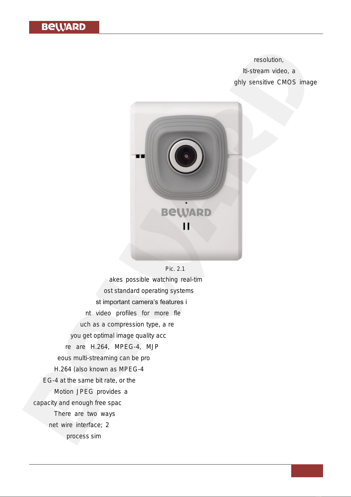
BEWARD N120 is a compact IP-camera (Pic. 2.1) with a 640x480 resolution, the built-in
Wi-Fi IEEE 802.11 b/g/n wireless interface, H.264/MPEG-4/MJPEG multi-stream video, a built-in
microphone, the microSD/SDHC card slot and a new generation highly sensitive CMOS image
sensor.
Pic. 2.1
BEWARD N120 makes possible watching real-time video recording from any part of the
world by means of the most standard operating systems and web browsers.
One of the most important camera’s features is the function which allows you to create and
customize different video profiles for more flexible and comfortable operation. Specifying
characteristics such as a compression type, a resolution, a maximum frame rate and a bit rate for
each profile, you get optimal image quality according to current channel bandwidth.
There are H.264, MPEG-4, MJPEG compression types the camera supports and
simultaneous multi-streaming can be provided.
H.264 (also known as MPEG-4 Part 10) offers higher video resolution than Motion JPEG or
MPEG-4 at the same bit rate, or the same video quality at a lower bit rate.
Motion JPEG provides a high quality video stream but it requires relatively big channel
capacity and enough free space for recording.
There are two ways to connect the camera to a network: 1) using a 10/100BASE-TX
Ethernet wire interface; 2) using a Wi-Fi IEEE 802.11 b/g/n wireless interface. To make Wi-Fi
connection process simpler the camera supports the WPS function.

Chapter 2. Overview
N120 Installation User Manual
5
A high quality of the image is provided by a progressive scan highly sensitive CMOS image
sensor and very efficient methods of video encoding also.
The microSD/SDHC memory cards support improves camera’s capabilities and makes its
operation safer. In case of disconnection all important information will be saved to the card.
2.1. Features
Optimal quality-price ratio
Progressive scan CMOS image sensor
MicroSD/SDHC memory cards support
Wi-Fi IEEE 802.11b/g/n with WPS support
Professional 16-channel software included
Simultaneous multi-streaming H.264/MPEG-4/M-JPEG for optimal playback and
video data recording
Viewing recorded files via the web interface with a built-in player
Built-in microphone
Built-in motion and audio detectors
Sending of images or video data by e-mail and transmission by FTP
Recording of images and video data to a shared folder (Windows or Linux OS) or to
NAS (Network Attached Storage)
ONVIF support
2.2. Specifications
1/4" progressive scan megapixel CMOS image sensor
Lens (optionally): f3.6 mm F2.0 (angle of view 58°(horizontally))
Resolution: 640x480, 320x240, 160x120
Sensitivity: 0.2 lux @ F2.0
Frame rate: up to 30 fps at all resolutions
Video encoding: H.264, MPEG-4, MJPEG
Simultaneous multi-streaming: H.264, MPEG-4, MJPEG formats
One-way audio streaming; compression: G711 µ-law, α-law, AMR
Wi-Fi IEEE 802.11b/g/n with WPS support
Protocols supported: Bonjour, TCP/IP, DHCP, PPPoE, ARP, ICMP, FTP, SMTP,
DDNS, NTP, UPnP, RTSP, RTP, RTCP, HTTP, TCP, UDP, 3GPP/ISMA RTSP
Power: 5V, 0.6 A DC
Operating temperature: 0 to +40oC

Chapter 2. Overview
N120 Installation User Manual
6
Operating humidity: 20-80% (without condensation)
ONVIF support
2.3. Package Contents
IP camera with a pre-installed lens (M12, f3.6 mm, F2.0)
Patch cord (1 m length)
Power supply: 5 V 1A
Wi-Fi antenna
Bracket with a mounting kit
CD with user manuals and software
Quick Installation Guide

Chapter 3. Product Description
N120 Installation User Manual
7
Chapter 3. Product Description
3.1. Front Side
Pic. 3.1
Focus adjustment ring: rotate the metal ring to set a focus (previously the focus is preset
and does not need to be adjusted).
Power LED: lights when the camera is switched on.
Red steady: power is supplied to the camera, the system is loading.
Blue steady: system loading is complete; the camera is ready to be configured through
the web interface.
Blinking violet: a) the camera is connecting to the Wi-Fi network via WPS; b) a
camera’s firmware is updating. Do not switch off the camera and do not close a
browser’s window till the process completing.
Unlit: power is not supplied to the camera or the LED indicator is turned off.
Network LED: lights when the camera is connected to the network.
Blinking blue: the camera is connected to the wired network.
Unlit: the camera is not connected to the wired network or the LED indicator is turned
off.
Built-in microphone: allows you to hear what happens in the surveillance area.
Chapter 3. Product Description
N120 Installation User Manual
8
3.2. Back Pane
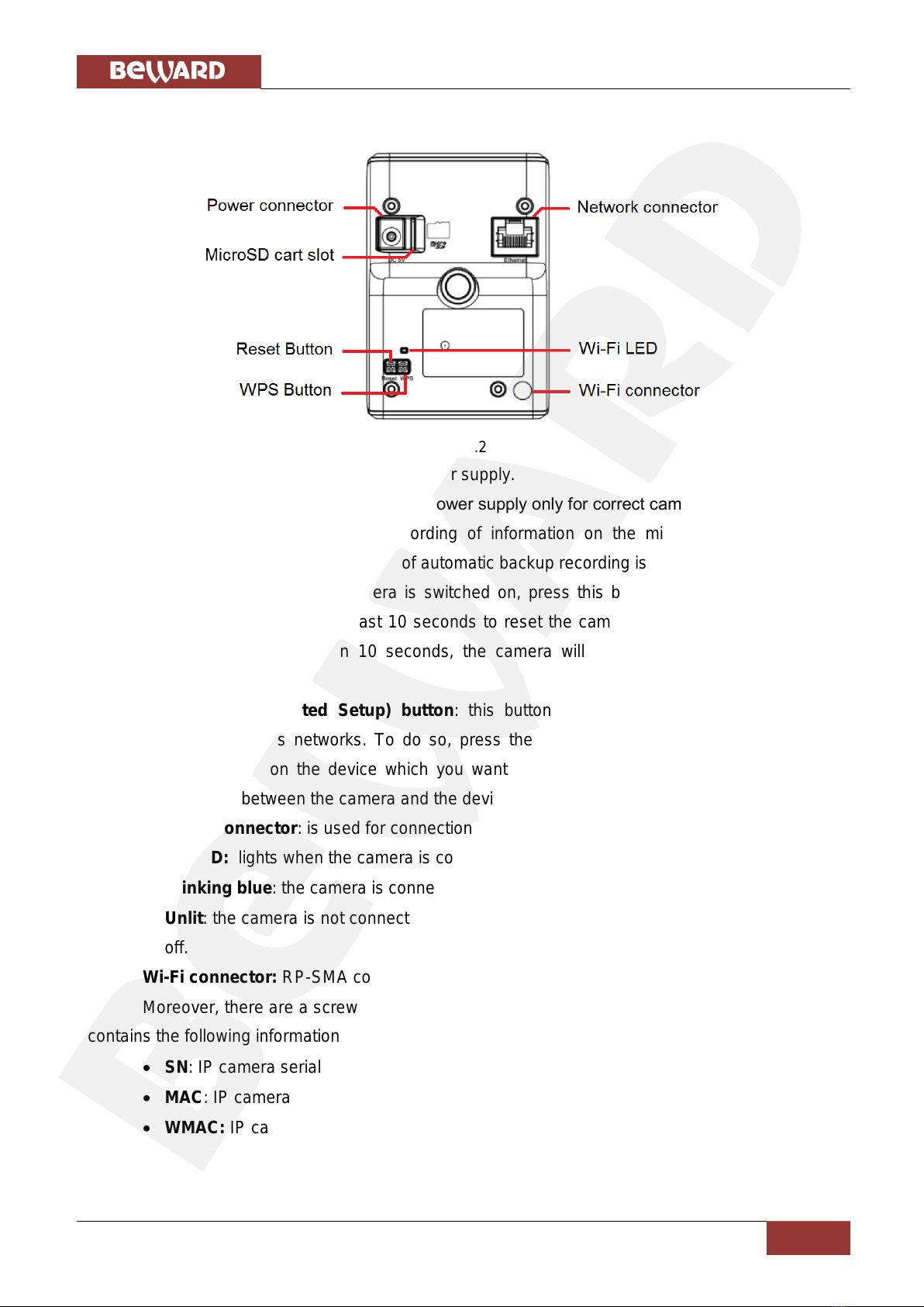
Pic. 3.2
Power connector: for 5 V, 1 A DC power supply.
It is recommended to use the original power supply only for correct camera’s operation.
MicroSD card slot: provides recording of information on the microSD/SDHC memory
cards. In case of disconnection an option of automatic backup recording is also available.
Reset button: when the camera is switched on, press this button to reboot the camera.
Press and hold this button for at least 10 seconds to reset the camera to factory defaults. If you
hold this button during less than 10 seconds, the camera will reboot without reset to factory
defaults.
WPS (Wi-Fi Protected Setup) button: this button provides simplified mechanisms to
configure secure wireless networks. To do so, press the WPS button on the camera and then
press the WPA button on the device which you want to connect the camera to. After that, the
wireless connection between the camera and the device will be established within 2 minutes.
Network connector: is used for connection to LAN or to the Internet by a RJ-45 connector.
Wi-Fi LED: lights when the camera is connected to the wireless network.
Blinking blue: the camera is connected to a wireless network.
Unlit: the camera is not connected to the wireless network or the LED indicator is turned
off.
Wi-Fi connector: RP-SMA connector for connecting Wi-Fi antenna.
Moreover, there are a screw hole for attaching a bracket on the rear side and a label which
contains the following information:
SN: IP camera serial number
MAC: IP camera MAC address (LAN)
WMAC: IP camera MAC address (WLAN)
Chapter 4. Installing the Camera and Cables’ Connecting
N120 Installation User Manual
9
Chapter 4. Installing the Camera and Cables’ Connecting
4.1. Overview of Connecting the N120 to a Network
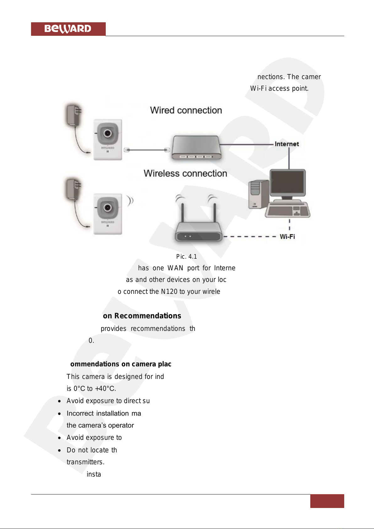
BEWARD N120 supports both wired (Ethernet) and wireless connections. The camera can
be connected directly to a computer or through a router, a switch, or a Wi-Fi access point.
Pic. 4.1
A common home router has one WAN port for Internet access and four LAN ports to
connect computers, IP cameras and other devices on your local network. Besides, the router must
support wireless interface to connect the N120 to your wireless network.
4.2. Installation Recommendations
This section provides recommendations that should be observed when mounting and
installing the N120.
Recommendations on camera placement:
This camera is designed for indoor video surveillance. The operating temperature range
is 0°С to +40°С.
Avoid exposure to direct sunlight and do not locate the camera near any heat sources.
Incorrect installation may cause undesirable “blind spots”, zones that are not visible to
the camera’s operator.
Avoid exposure to high humidity.
Do not locate the camera near any electrical appliances which can be electromagnetic
transmitters.
When installing the camera, be convinced of possibility of free laying connecting cables.

Chapter 4. Installing the Camera and Cables’ Connecting
N120 Installation User Manual
10
Avoid unstable installation, which may allow exposure to high vibration. This may reduce
motion detection performance and image crispness in whole.
Cameras in video surveillance system should be installed so that probability of their
damage or viewing direction changing or any other unauthorized action was excluded.
The viewing direction should be clearly determined at the moment of the camera’s
installation.
Recommendations on twisted pair cable installation:
In corridors, it is advisable to install electric and feeble-current cables in different
conduits that are disposed on different walls.
Twisted pair and electric cables can be installed in the same conduit using different
sections of the cable that have solid longitudinal partitions with at least 0.25 h of fire
resistance, which are made of non-combustible material and should be positioned in
work areas at distance of 15 meters maximum if the electrical power does not exceed 5
kW.
Electric and feeble-current cables should be placed in parallel to each other at distance
of at least 50 mm in different conduits or different sections of conduit. If the electric field
strength from the electric cables exceeds 3 V/m, you should increase the distance
between the electric and feeble-current cables or reduce the electromagnetic noise.
Twisted pair and electric cables should cross each other at right angles.
Unshielded twisted pair cables should be located at distance of at least 125 mm from
fluorescent gas-discharge lamps or from other high-voltage discharge devices.
Unshielded twisted pair cables should be located at distance of at least 1.5 meters from
electromagnetic interference sources that produce electric field strength exceeding 3
V/m.
Switchboards with pinned unshielded twisted pair cables should be located at distance
of at least 3 meters from electromagnetic interference sources that produce electric field
strength exceeding 3 V/m.
Entire twisted pair cables should be arranged between the points of connection so the
cable run is as short as possible.
Minimum cable bending radius is four times the cable diameter (or 1 inch=2.5 cm) or it is
also acceptable to install the cable so that the cable bending radius is 2 inches (5 cm).
Maximum length of the entire segment is 100 meters.
When connecting over Wi-Fi, take notice that the signal strength depends on many
factors such as the distance to the access point, electromagnetic waves, configuration of
the place where the camera is installed, etc.

Chapter 4. Installing the Camera and Cables’ Connecting
N120 Installation User Manual
11
4.3. Installing the Camera
Step 1: attach the bracket to the surface using 3 self-tapping screws.
Step 2: loosen the bracket screws to move the camera to the desired position.
Step 3: attach the camera to the bracket, adjust the tilt angle and fasten the camera (Pic
4.2).
Pic 4.2
4.4. Wired Connection to a Network
Step 1: provide the camera with power using the included 5 V, 1 A power supply:
Step 2: use the supplied RJ45 cable to connect the camera to a network (a LAN port of the
router).
You can purchase a network cable separately or if you have the materials, tools and skills,
you can make a network cable by yourself.
A straight RJ-45 cable (UTP category 5e)
The table below shows an example of a patch cord to connect the camera to a computer or
a network switch.

Chapter 4. Installing the Camera and Cables’ Connecting
N120 Installation User Manual
12
One end
Other end
1: White and orange
1: White and orange
2: Orange
2: Orange
3: White and green
3: White and green
4: Blue
4: Blue
5: White and blue
5: White and blue
6: Green
6: Green
7: White and brown
7: White and brown
8: Brown
8: Brown
To make a network cable, you need the following materials: a UTP category 5e cable, two
RJ-45 connectors and an RJ-45 crimping tool.
Assembling the pairs of wires in the correct order (see the table above) ensures data
transfer speed of 100 Mbps.
Chapter 5. Setting up the Wired Connection for Windows 7
N120 Installation User Manual
13
Chapter 5. Setting up the Wired Connection for Windows 7
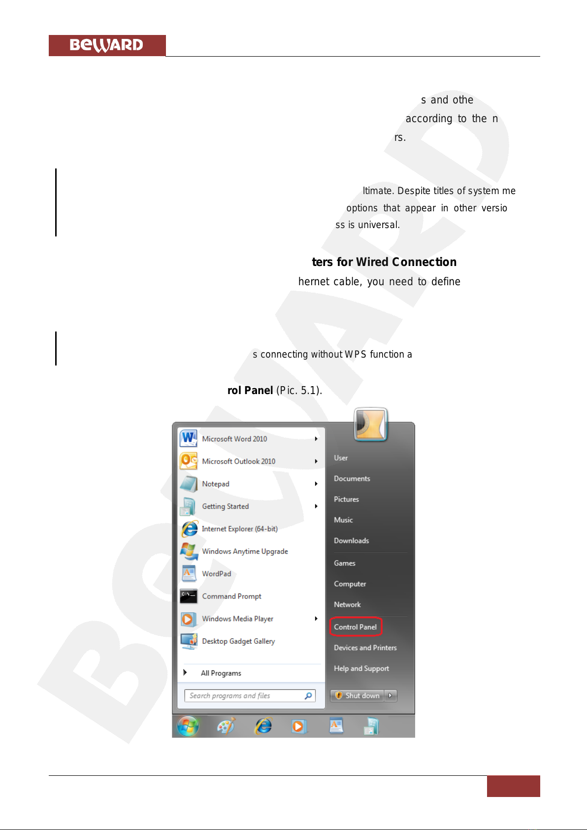
To make the N120 IP camera work together with computers, laptops and other devices in
your local network, you need to connect this camera to the network according to the network
parameters. This chapter explains how to define the network parameters.
NOTE:
The connection establishment process is shown for OS Windows 7 Ultimate. Despite titles of system menus
and options may differ from the titles of system menus and options that appear in other versions of
Windows, the procedure of the connection establishment process is universal.
5.1. Defining the Local Network Parameters for Wired Connection
When connecting the camera using an Ethernet cable, you need to define local network
parameters.
NOTE:
It is necessary to do in case of using wireless connecting without WPS function also.
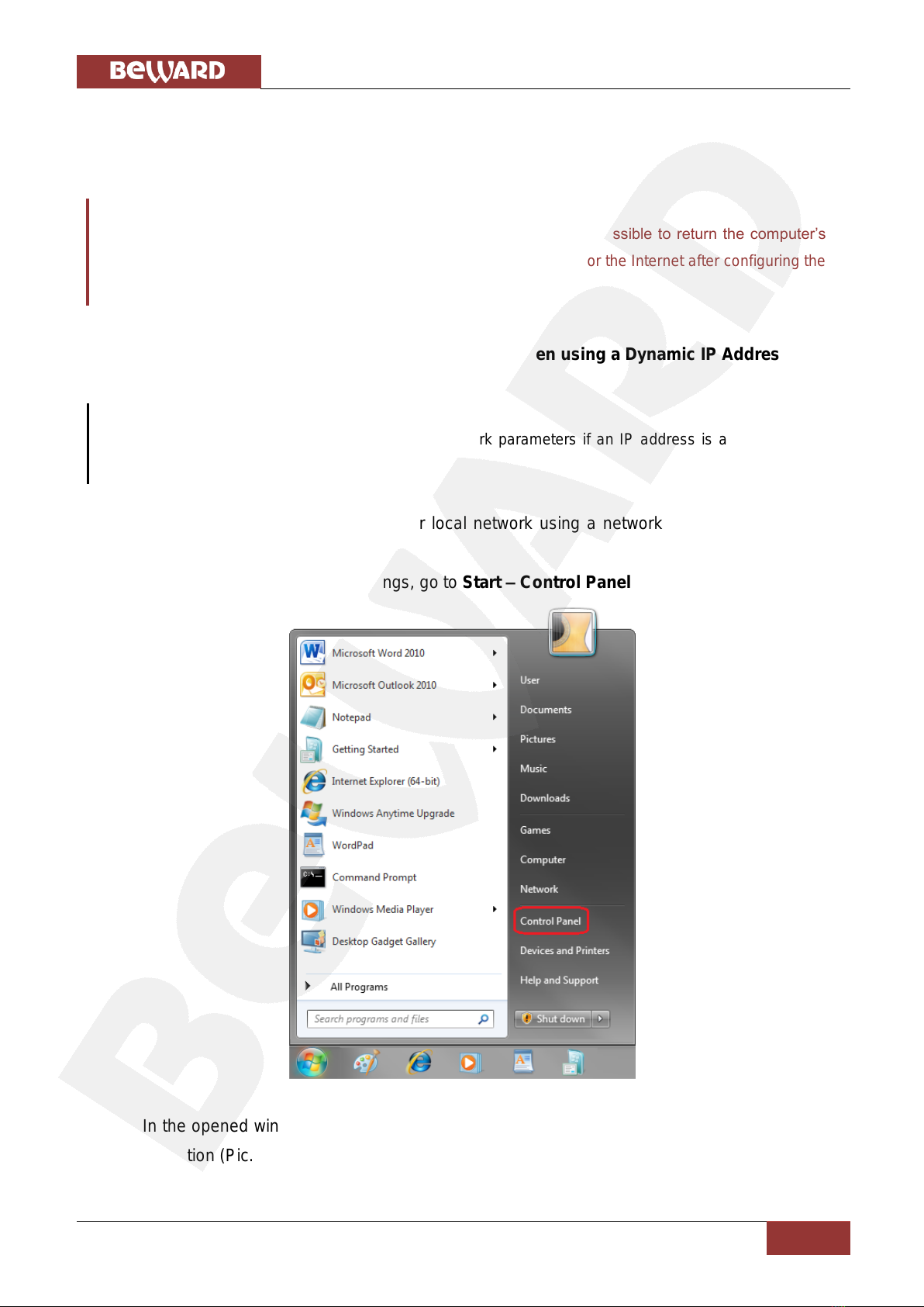
To do so, go to Start –Control Panel (Pic. 5.1).
Pic. 5.1
Chapter 5. Setting up the Wired Connection for Windows 7
N120 Installation User Manual
14
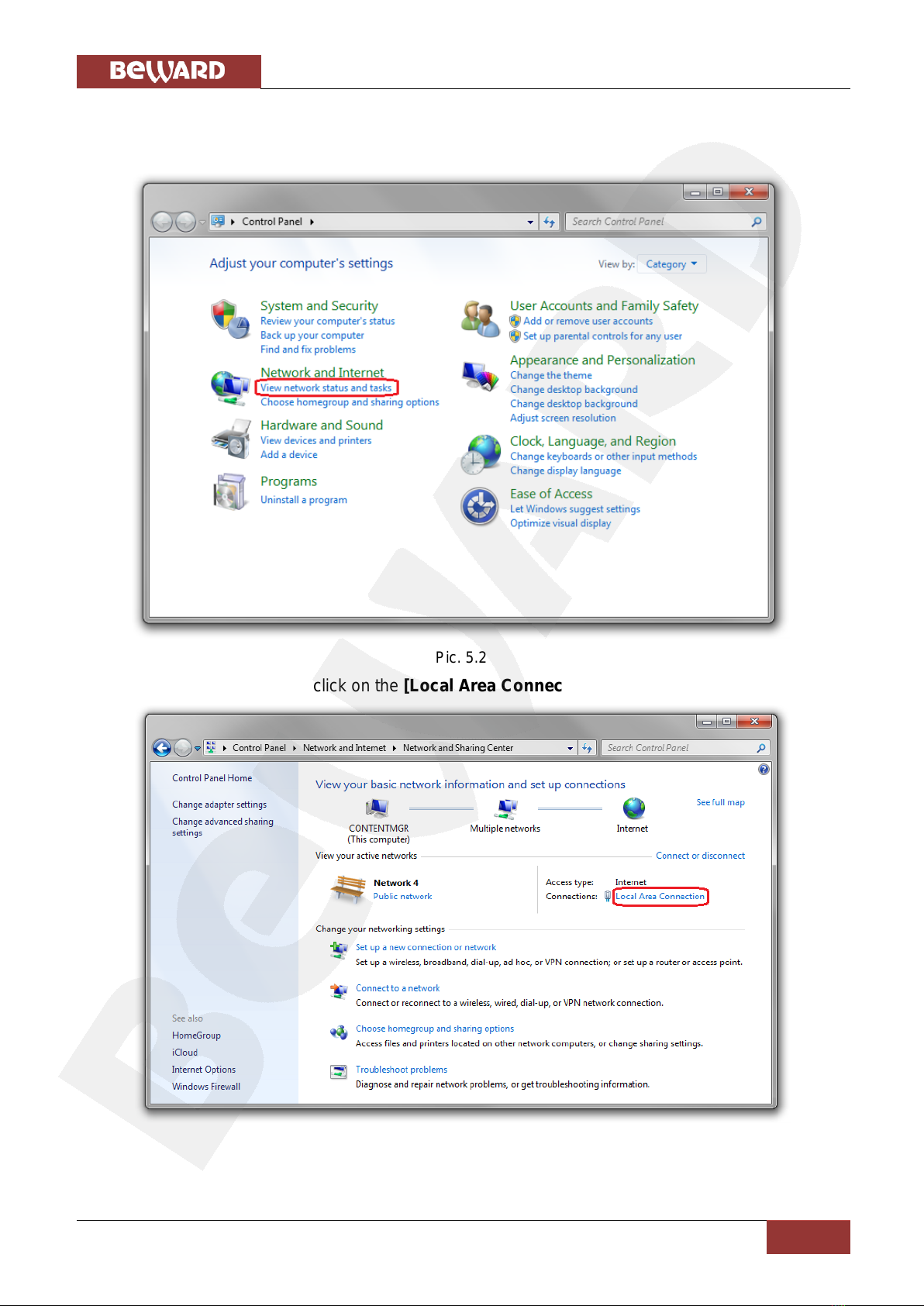
In the opened window click on the [View network status and tasks] in the [Network and
Internet] section (Pic. 5.2).
Pic. 5.2
In the opened window click on the [Local Area Connection] (Pic. 5.3).
Pic. 5.3

Chapter 5. Setting up the Wired Connection for Windows 7
N120 Installation User Manual
15
NOTE:
If there are several active networks, choose the one that you are going to connect your camera to.
In the opened window click the [Properties] button (Pic. 5.4).
Pic. 5.4
In the opened window select the [Internet Protocol Version 4 (TCP/IPv4)] menu item and
click the [Properties] button (Pic. 5.5).
Pic. 5.5
Chapter 5. Setting up the Wired Connection for Windows 7
N120 Installation User Manual
16
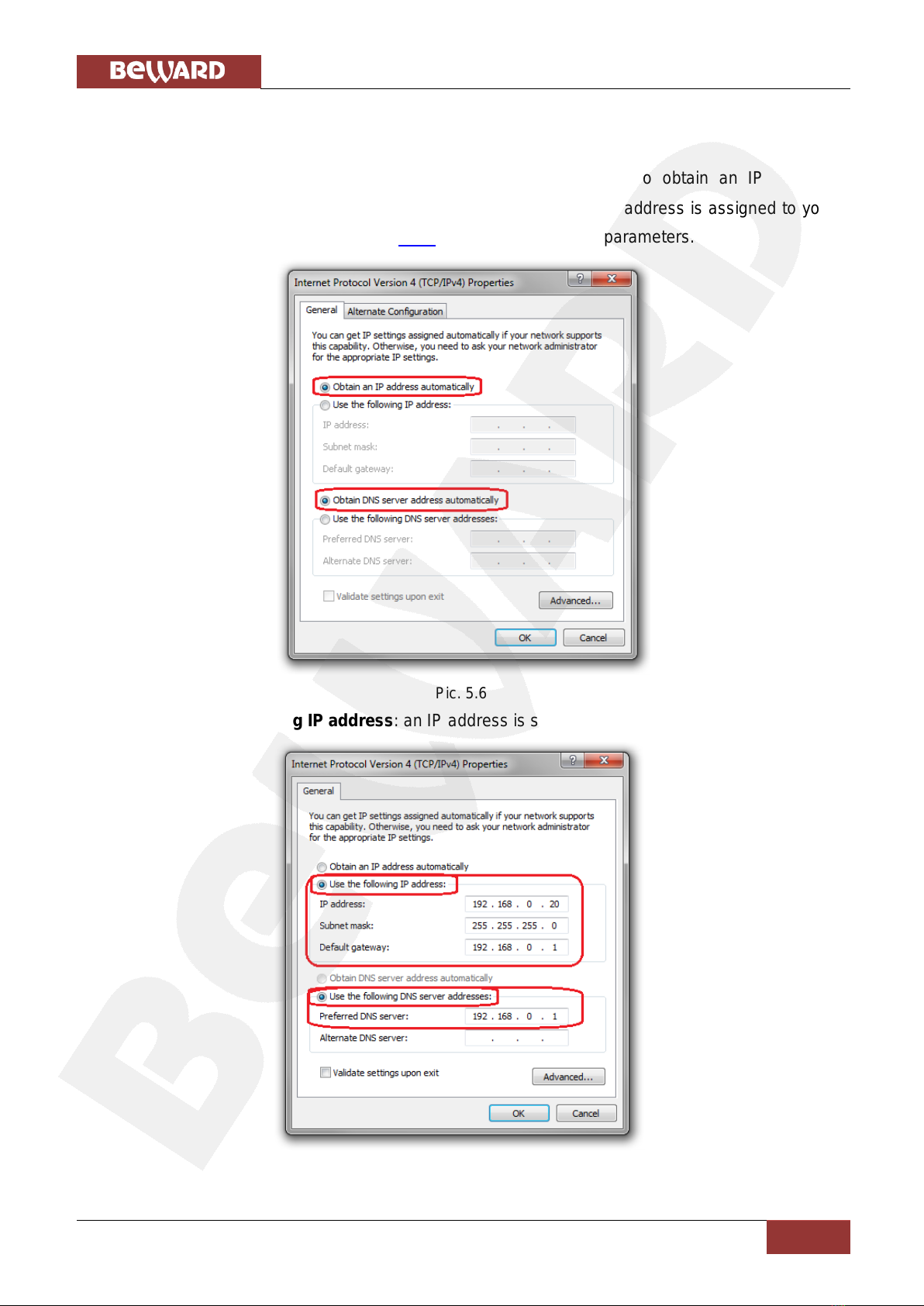
The window opens displaying information about the network connection settings. There are
two ways to configure the IP address:
1. Obtain an IP address automatically: select this option to obtain an IP address
automatically from a DHCP-server on your network (Pic. 5.6). If an IP address is assigned to your
computer automatically, go to paragraph 5.1.1 to define the network parameters.
Pic. 5.6
2. Use the following IP address: an IP address is specified manually (Pic. 5.7).
Pic. 5.7
Chapter 5. Setting up the Wired Connection for Windows 7
N120 Installation User Manual
17
Make a note of the following parameters: IP address, Subnet mask, Default gateway, DNS
server.
IMPORTANT!
If you do not make a note of the network parameters, then it will be impossible to return the computer’s
network settings to their initial state and to connect it to a local network or the Internet after configuring the
N120.
5.1.1. Defining the Local Network Parameters when using a Dynamic IP Address
NOTE:
This paragraph explains how to define the local network parameters if an IP address is assigned to your
computer automatically (by DHCP-server).
Connect a computer (laptop) to your local network using a network cable and wait till the
connection process completing.
To define the local network settings, go to Start –Control Panel (Pic. 5.8).
Pic. 5.8
In the opened window click on the [View network status and tasks] in the [Network and
Internet] section (Pic. 5.9).

Chapter 5. Setting up the Wired Connection for Windows 7
N120 Installation User Manual
18
Pic. 5.9
In the opened window click on the [Local Area Connection] (Pic. 5.10).
Pic. 5.10
NOTE:
If there are several active networks, choose the one that you are going to connect your camera to.
Chapter 5. Setting up the Wired Connection for Windows 7
N120 Installation User Manual
19
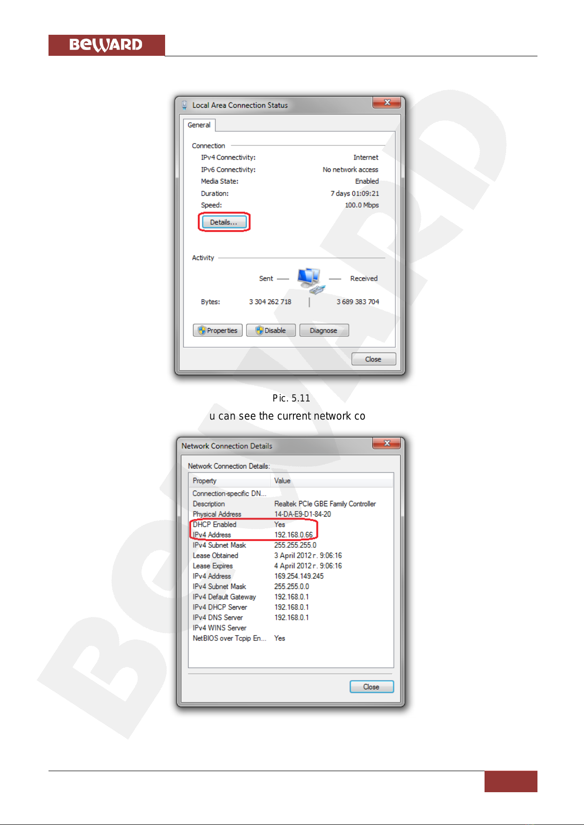
In the opened window click the [Details] button (Pic. 5.11).
Pic. 5.11
In the opened window you can see the current network connection details (Pic. 5.12).
Pic. 5.12
Table of contents
Other Beward IP Camera manuals

Beward
Beward N6601 User manual

Beward
Beward N300 User manual

Beward
Beward N37210 User manual

Beward
Beward N 1000 Instruction Manual

Beward
Beward N6603 User manual

Beward
Beward N13201 User manual

Beward
Beward N 13102 User manual

Beward
Beward N6603 User manual

Beward
Beward N13100 User manual

Beward
Beward N300 Instruction Manual


