BFW Long Island Technology Group Hatteras User manual

LED Light Source
Operating Manual
HatterasTM


Table of Content
Symbol Description .....................................................................................2
Warnings and Cautions................................................................................3
Package Content .......................................................................................................... 5
Intended Use ............................................................................................................... 5
Unintended Use........................................................................................................... 5
Operation....................................................................................................6
Light Source ................................................................................................................. 6
Cleaning and Maintenance ..........................................................................7
Light Source ................................................................................................................. 7
Specifications ..............................................................................................8
Electromagnetic Compatibility.....................................................................9
Troubleshooting and Service .....................................................................13
Troubleshooting......................................................................................................... 13
Warranty and Service ................................................................................................ 14

2
Symbol Description
These important symbols may appear on your Long Island Technology Group Optic light source. Please note
their meaning.
Attention: Read this owner’s manual for all warnings, precautions and instructions for use.
CE marking of conformity indicates this device complies with European Directive 93/42 EC
on medical devices and Directive 2002/95/EC on the restriction of the use of certain hazard-
ous substances in electrical and electronic equipment.
The UL mark indicates this product has been tested to, and conforms to applicable stan-
dards.
More information for this product can be found in this operating manual.
AS TO ELECTRICAL SHOCK, FIRE AND MECHANICAL HAZARDS ONLY
IEC 60601-1 Edition 3 (2008), IEC 60601-1-2 Edition 3 (2007), IEC 60601-2-18 Edition 3 (2009)
ANSI/AAMI E-S60601-1 (2005), CAN/CSA-C22.2 No. 60601-1 (2008)

3
Warnings and Cautions
Users of this product should be thoroughly trained in the appropriate medical procedures. Also they should
read and understand this owner’s manual for this light source and all equipment used with it.
!DO NOT shine light into eyes. Eye injury may result.
!DO NOT use in the presence of ammable anesthecs or other ammable mixtures. Explosion or Fire
may result.
!DO NOT use if packaging is damaged.
!Service must be performed only by Long Island Technology Group or properly trained biomedical tech-
nicians.
!DO NOT operate light closer then 3 inches to ssue. Tissue Damage may result.
!DO NOT use non-approved ber opc cables. Damage to the Haeras™ or ber opc cable may result.
!DO NOT block the light emission by turning the turret to cover the opening. Fire or damage to the Hat-
teras™ may result.
!DO NOT plug or unplug AC cord with wet hands. Electrical shock may result.
!DO NOT stack the HaerasTM or obstruct the vents. Damage to the HaerasTM or Fire may result.
!Medical Electrical Equipment needs special precauons regarding EMC and needs to be installed and
put in service according to the EMC informaon in the Electromagnec Capability of this manual.
!APPLIED PARTS of other ME EQUIPMENT used within the CONFIGURATION FOR ENDOSCOPIC APPLICA-
TION must be TYPE BF APPLIED PARTS or TYPE CF APPLIED PARTS
!Before each use, the compability of the ENDOSCOPIC Equipment with any ACCESSORIES and/or EN-
ERGIZED ENDOTHERAPY DEVICES should be checked according to any criteria for safe use dened in the
instrucons for use
!DB9 Serial port located in the rear is for Manufacturer use only. Use of unauthorized accessories may
negavely aect EMC performance and result in non-compliance. Do not use a DB9 cable longer than 3
m (9.84 ).

4
Warnings and Cautions
!WARNING Use of this equipment adjacent to or stacked with other equipment should be avoided
because it could result in improper operaon. If such use is necessary, this equipment and the other
equipment should be observed to verify that they are operang normally.
!WARNING Use only components and accessories listed on page 5 and 8 of this manual. Failure to do so
may decrease system performance, may lead to unsafe operaon, may negavely aect EMC perfor-
mance, and could result in non-compliance and could void the warranty.
!WARNING Portable RF communicaons equipment (including peripherals such as antenna cables and
external antennas) should be used no closer than 30 cm (12 inches) to any part of the HaerasTM, in-
cluding cables specied by the manufacturer. Otherwise, degradaon of the performance of this equip-
ment could result.

5
Warnings and Cautions
Package Content
1 - Hatteras™ LED Light Source
1 - Operating Manual Card
1 - Medical Grade Power Cable
Intended Use
The Hatteras™ Light Source is a LED light source designed to be a replacement for similar halogen light sources.
The device is intended to be used with a fiber optic cable and an optic system. A rotating turret accommodates
fiber optic cables from Wolf, Storz, Olympus and ACMI/BFW products. The light is an excellent supplementary
light source for examinations and procedure. The advantage of the HatterasTM system is that it uses an LED
light engine which runs cooler then halogen light engine. The intended environment for use is for Professional
Health Care except for near active HF Surgical Equipment and the RF shielded room of an ME System for mag-
netic resonance imaging. Please follow the maintenance instructions on p7 in order to maintain basic safety.

6
Operation
Light Source
1. Plug AC cable from the AC cable receptacle (A) into a medical grade power supply.
2. Flip the main power switch (B) to the on position.
A
B
C
3. Press the Power button (D) to turn the system to standby.
!If you see an error on the display (F) please consult the Troubleshoong secon on page 11.
4. Insert your fiber optic cable into the active port as indicated by the gray dot (J).
5. Press the standby button (G) to turn the light on at the most recent brightness or 80% brightness, shown
on the display (F).
!The light will not come on or remain on if there is no ber in place the acve port. Press and hold the
standby buon for 3 seconds to turn the LED on with no ber present.
6. Pressing the + (H) or – (I) buttons to increase or decrease the light brightness by 10%.
7. Pressing the standby button (G) again will turn the light off.
8. Pressing the dim button (E) will change the brightness level of the display (F).
D
E
F
GH
I
J
A. AC Cable Receptacle
B. Main Power Switch
C. DB9 Serial Port- Manufactur-
er use only
D. Power Button
E. Dim Button
F. Display
G. Standby Button
H. Increase Button
I. Decrease Button
J. Active Port Indicator

7
Cleaning and Maintenance
Light Source
1. Clean the HatterasTM with an alcohol wipe.
2. Use a can of compressed air to clean out any dust accumulations.
!DO NOT pour cleaning soluon directly on the surface of the HatterasTM
!DO NOT use any sterilizaon process or cleaning process using excessive heat or humidity as it will
damage the device
!NEVER immerse the light source in any type of liquid
NOTE. Damaging any part of the system with the use of an improper cleaning agent or cleaning process will
void all warranties.

8
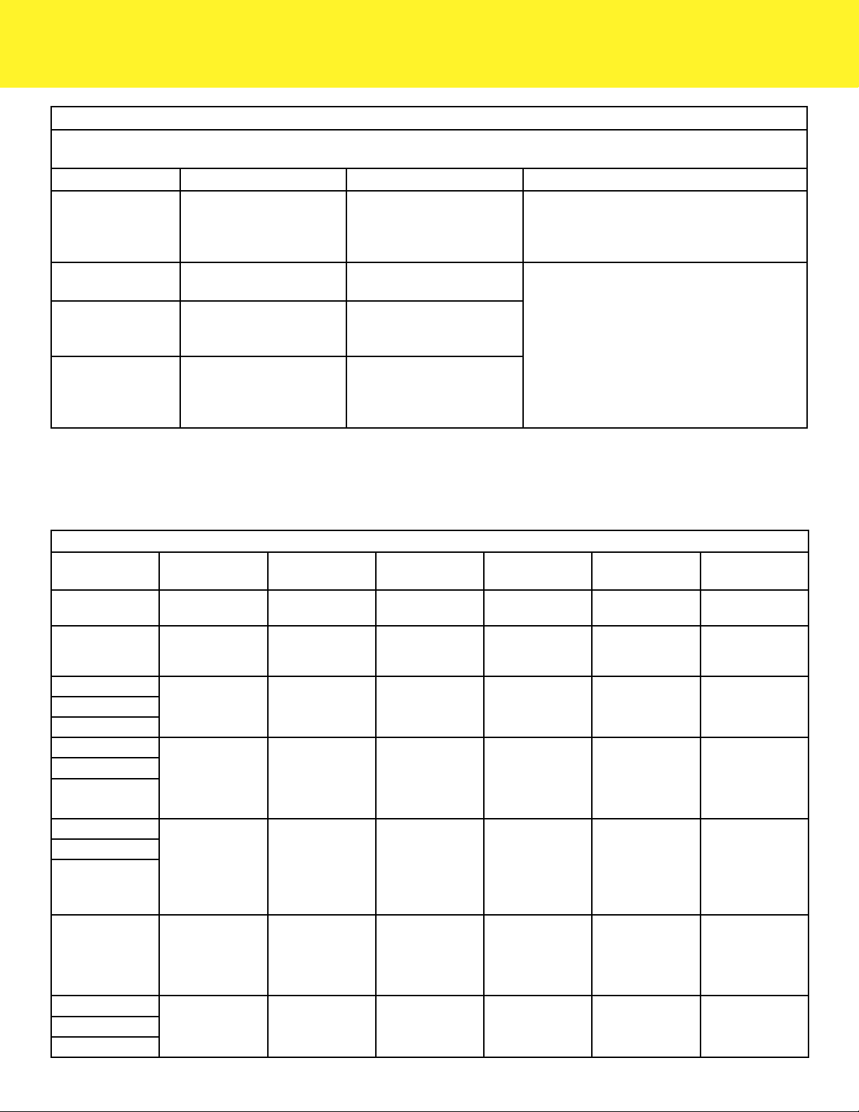
Specications
Classification
Classification & Type FDA Class II: Medical Electrical Equipment per IEC
60601-1/CAN/CSA c22.2 No. 60601-1
Safety , EMC, and Regulatory Compliance IEC 60601-1 Edition 3 (2008)
IEC 60601-1-2 Edition 4 (2014)
IEC 60601-2-18 Edition 3 (2009)
AAMI ES60601-1 Edition 1 (2005)
CSA C22.2 NO 60601-1:08 Edition 2 (2008)
Mechanical
Light Source
LxWxH 14.0” x 5.0” x 8.0”
Indicators 7-segment display
Weight 9.6 lbs
Electrical
Light Source
Input Voltage 100-240 VAC, 50/60 Hz @ 1 Ampere
Line Cord (IEC 60320 - Hospital Grade) Maximum Length 10ft
Fuse 5 mm x 20 mm, 4A, 250VAC, high breaking capacity,
slow blow fuse
Environment
Operation Temperature 50 Degrees F (10 C) to 104 Degrees F (40 C)
Operating Humidity 20% to 80% RH non-condensing
Storage Temperature 14 Degrees F (-10 C) to 140 Degrees F (60 C)
Storage Humidity 10% to 95% RH non-condensing
Performance
Lamp Type LED
Lamp Life 10,000+ hours
Lamp Color Temperature Average 5,700 Kelvin measured at 100% intensity, CRI
of at least 70
Output Type Approximately 160,000+ Lux at 14 inches when used
with BFWTM AtoNTM Headlight
Over-Temperature Protection device automatically shuts down to prevent
overheating. Fans will remain on during Over-Tem-
perature Protection. Power OFF and power unit On to
relight lamp.
9
Electromagnetic Compatibility
Portable and mobile RF communications equipment can affect medical electrical equipment.
Guidance and manufacturer’s declaration-electromagnetic emissions
e HatterasTM is intended for use in the electromagnetic environment specied below. e customer or the user of the HatterasTM
should assure that it is used in such an environment
Immunity
Test
IEC 60601 Test
Level Compliance Level Electromagnetic Environment Guidance
Conducted
RF IEC
61000-4-6
Radiated
RF IEC
61000-4-3
3 Vrms 150kHz - 80
MHz
3V/meter 80 MHz -
2.5 GHz
3 Vrms
3V/m from
30MHz to 1GHz,
3V/m for 1 GHz to
25GHz; (1000 Hz
80% Modulated
Test Signal)
Portable and mobile RF communications equipment should be used no
closer to any part of the HatterasTM, including cables, than the recom-
mended separation distance calculated from the equation application to
the frequency of the transmitter.
Recommended Separation Distance:
Battery Operated Device
d = 1.17√P
d = 1.17√P 80 MHz to 800 MHz
d = 2.23√P 800 MHz to 2.5 GHz
Where P is the maximum output power rating of the transmitter in
watts(W) according to the transmitter manufacturer and d is the recom-
mended separation distance in meters (m).
Field strengths from xed RF transmitters, as determined by an electro-
magnetic site survey (1), should be less than the compliance level in each
frequency range (2).
Interference may occur in the vicinity of equipment marked with the
following symbol:

10
Electromagnetic Compatibility
NOTE 1: At 80 MHz, the separation distance for the higher frequency range applies.
NOTE 2: ese guidelines may not apply in all situations. Electromagnetic propagation is aected by absorption and reection from
surfaces, objects, and people.
(1) Field strengths from xed transmitters, such as base stations for radio (cellular/cordless) telephones and land mobile radios, am-
ateur radio, AM and FM radio broadcast and TV broadcast cannot be predicted theoretically with accuracy to asses the electromag-
netic environment due to xed RF transmitters, an electromagnetic site survey should be considered. If the measured eld strength
in the location in which the HatterasTM is used exceeds the applicable RF compliance level above, the HatterasTM should be observed
to verify normal operation. IF abnormal performance is observed, additional measure may be necessary, such as re-orienting or
relocating the HatterasTM.
(2) Over the frequency range 150kHz to 80MHz, eld strengths should be less than 3 V/m.
Recommended separation distances between portable and mobile RF communications equipment and the HatterasTM
e HatterasTM is intended for use in an electromagnetic environment in which radiated RF disturbances are controlled. e custom-
er or user of the HatterasTM can help prevent electromagnetic interference by maintaining a minimum distance between portable and
mobile RF communications equipment (transmitters) and the HatterasTM as recommended below, according to the maximum output
power of the communications equipment.
Rate maximum output power
of transmitter
Separation distance according to frequency of transmitter in meters
W 150 kHz to 80 MHz
d = 1.17 P
80 MHz to 800 MHz
d = 1.17 P
800 MHz to 2.5 GHz
d = 2.23 P
.01 0.12 0.12 0.23
.1 0.37 0.37 0.737
1 1.17 1.17 2.33
10 3.0 3.70 7.37
100 11.70 11.70 23.30
For transmitters rated at a maximum output power not listed above, the recommended separate distance d in meters (m) can be esti-
mated using the equation applicable to the frequency of the transmitter, where P is the maximum output power rating of the trans-
mitter in watts (W) according to the transmitter manufacturer.
NOTE 1: At 80 MHz and 800 MHz, the separation distance for the higher frequency range applies.
NOTE 2: e ISM (industrial, scientic and medical) bands between 150 kHz and 80 MHz are 6.765 MHz to 6.795 MHz; 13.553
MHz to 13.567 MHz; 26.957 MHz to 27.283 MHz; and 40.66 MHz to 40.70 MHz.
NOTE 3: An additional factor of 10/3 has been incorporated into the formulae used in calculated the recommended separation dis-
tance for transmitters in the ISM frequency bands between 150 kHz and 80 MHz and in the frequency range 80 MHz to 2.5 GHz to
decrease the likelihood that mobile/portable communications equipment could cause interference if it is inadvertently brought into
patient areas.
NOTE 4: ese guidelines may not apply in all situations. Electromagnetic propagation is aected by absorption and reection from
surfaces, objects, and people.

11
Electromagnetic Compatibility
Guidance and manufacturer’s declaration - electromagnetic immunity
e HatterasTM is intended for use in the electromagnetic environment specied below. e customer or the end user of the Hatter-
asTM should assure that it is used in such an environment.
Immunity test IEC 60601 test level Compliance level Electromagnetic environment - guidance
Radiated RF elec-
tromagnetic eld
& Proximity elds
from RF wireless
communications
equipment
IEC 61000-4-3
Radiated: 80MHz to
2700MHz at 3V/m
IEC 61000-4-3
Radiated: 80MHz to
2700MHz at 3V/m
Radiated RF levels should be that of a typical
commercial or hospital environment
Conducted Distur-
bances induced by
RF elds
IEC 61000-4-6
Conducted: 150kHz to
80MHz at 3Vrms outside the
ISM band, 6Vrms in the ISM
band
IEC 61000-4-6
Conducted: 150kHz to
80MHz at 3Vrms outside the
ISM band, 6Vrms in the ISM
band
Mains power quality should be that of a typi-
cal commercial or hospital environment.
Electrostatic dis-
charge (ESD)
IEC 61000-4-2
± 8 kV contact
± 15 kV air
IEC 61000-4-2
± 8 kV contact
± 15 kV air
Floors should be wood, concrete or ceramic
tile. If oors are covered with synthetic mate-
rial, the relative humidity should be at least 30
%. e user of the (HatterasTM) should avoid
situations that could result in excess electro-
static discharge.
Electrical Fast Tran-
sient/burst
IEC 61000-4-4
± 2 kV for power supply lines
100kHz repetition frequency
IEC 61000-4-4
± 2 kV for power supply lines
100kHz repetition frequency
Mains power quality should be that of a typi-
cal commercial or hospital environment.
Surge
IEC 61000-4-5
± 1 kV line(s) to line(s)
± 2 kV line(s) to earth
IEC 61000-4-5
± 1 kV line(s) to line(s)
± 2 kV line(s) to earth
Mains power quality should be that of a typi-
cal commercial or hospital environment.
Voltage dips, short
interruptions and
voltage variations on
power supply input
lines
IEC 61000-4-11
0 % UT; 0,5 cycle
At 0°, 45°, 90°, 135°, 180°,
225°, 270° and 315°
0 % UT; 1 cycle
and
70 % UT; 25/30 cycles
Single phase: at 0°
0 % UT; 250/300 cycle
IEC 61000-4-11
0 % UT; 0,5 cycle
At 0°, 45°, 90°, 135°, 180°,
225°, 270° and 315°
0 % UT; 1 cycle
and
70 % UT; 25/30 cycles
Single phase: at 0°
0 % UT; 250/300 cycle h)
Mains power quality should be that of a
typical commercial or hospital environment.
If the user of the HatterasTM requires contin-
ued operation during power mains interrup-
tions, it is recommended that the HatterasTM
be powered from an uninterruptible power
supply or a battery.
Proximity elds
from RF wireless
communications
equipment
IEC 61000-4-3
See Table 9 on p12.
IEC 61000-4-3
See Table 9 on p12.
RF wireless communications equipment
should be used no closer than 30 cm to the
HatterasTM.
Power frequency
(50/60 Hz) magnetic
eld
IEC 61000-4-8
30A/m
IEC 61000-4-8
30A/m
Power frequency magnetic elds should be at
levels characteristic of a typical location in a
typical commercial or hospital environment.
NOTE UTis the a.c. mains voltage prior to application of the test level.
12
Electromagnetic Capability
Guidance and manufacturer’s declaration - Electromagnetic Emissions
e HatterasTM is intended for use in the electromagnetic environment specied below. e customer or the end user of the Hatter-
asTM should assure that it is used in such an environment.
Emissions Test IEC 60601 test level Compliance level Electromagnetic environment - guidance
RF emissions
CISPR 11
Group 1 Group 1
e HatterasTM uses RF energy only for its
internal function. erefore, its RF emissions are
very low and are not likely to cause any interfer-
ence in nearby electronic equipment.
RF emissions
CISPR 11 Class A Class A
e HatterasTM is suitable for use in all establish-
ments other than domestic and those directly
connected to the public low-voltage power
supply network that supplies buildings used for
domestic purposes.
Harmonic emissions
IEC 61000-3-2
Class A Class A
Voltage uctuations/
icker emissions
IEC 61000-3-3
Complies Complies
NOTE e EMISSIONS characteristics of this equipment make it suitable for use in industrial areas and hospitals (CISPR 11 class
A). If it is used in a residential environment (for which CISPR 11 class B is normally required) this equipment might not oer adequate
protection to radio-frequency communication services. e user might need to take mitigation measures, such as relocating or re-ori-
enting the equipment.
Table 9 - Test specications for Enclosure Port Immunity to RF wireless communications equipment
Test frequency
(MHz)
Band (MHz) Service Modulation Maximum power
(W)
Distance (m) Immunity Test
Level (V/m)
385 380 - 390 TETRA 400 Pulse modulation
18Hz 1,8 0,3 27
450 430 - 470 GMRS 460,
FRS 460
FM
± 5Hz deviation
1 kHz sine
2 0,3 28
710
704 - 787 LTE Band 13, 17 Pulse modulation
217 Hz 0,2 0,3 9745
780
810
800 - 960
GSM 800/900,
TETRA 800,
iDEN 820,
CDMA 850,
LTE Band 5
Pulse modulation
18Hz 2 0,3 28
870
930
1720
1700 - 1990
GSM 1800;
CDMA 1900;
GSM 1900;
DECT;
LTE Band 1, 3,
4, 25; UMTS
Pulse modulation
217 Hz 2 0,3 28
1845
1970
2450 2400 - 2570
Bluetooth,
WLAN,
802.11 b/g/n,
RFID 2450,
LTE Band 7
Pulse modulation
217 Hz 2 0,3 28
5240
5100 - 5800 WLAN 802.11 a/n Pulse modulation
217 Hz 0,2 0,3 95500
5785
13
Troubleshooting and Service
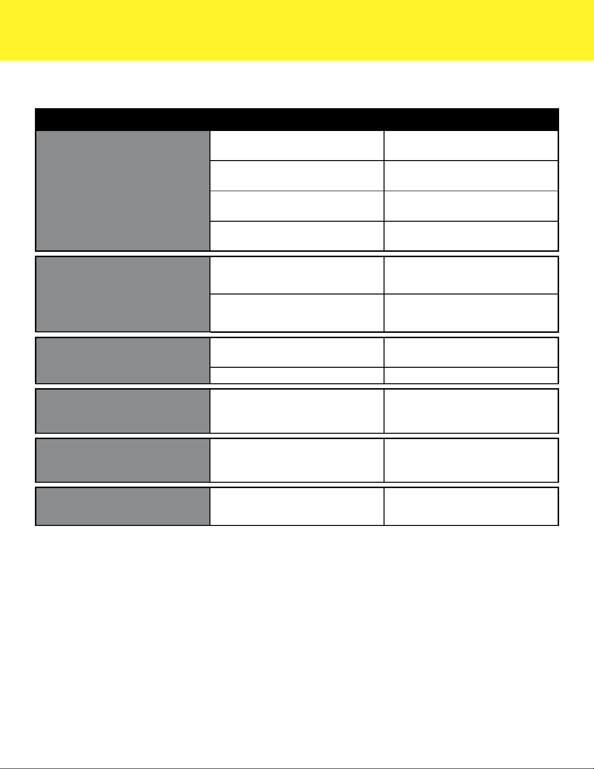
Troubleshoong
Symptom Possible Issue Solution
No Power
Main power cord not plugged into
socket Plug in cord
Fuse is blown Return HatterasTM to manufacturer
for service
Main power switch is not fully
engaged Toggle ON/OFF switch
Internal component is not func-
tioning
Return HatterasTM to manufacturer
for service
Light Does not Illuminate
Fiber is not fully inserted into the
active port
Push fiber into the active port until
it clicks
Internal component is not func-
tioning
Return HatterasTM to manufacturer
for service
Low Light Output LED is nearing end of life Return HatterasTM to manufacturer
for service
Fiber optic cable is damaged Replace Fiber optic cable
“Er0” appears in the dis-
play
LED is operating warmer than
normal
Remove objects around the Hatter-
asTM that may be blocking the vents
or producing heat
“Er1” appears in the dis-
play
LED has reached a critical tem-
perature and has shut its self off for
safety
Remove objects around the Hatter-
asTM that may be blocking the vents
or producing heat
“Er2” appears in the dis-
play One of the fans has stalled Remove obstructions in the vents
14
Troubleshooting and Service
Warranty and Service
Warranty against manufacturer’s defects applies to the following components of the Hatteras™ under normal
use for one (1) year from the date of sale from Long Island Technology Group (includes parts and labor).
• LED Optics and Controller
• Cables and Connectors
The warranty does not cover products damaged by the following:
• Accident, misuse, abuse, or alteration
• Servicing by unauthorized persons
• Use with unauthorized accessories
• Connection to incorrect current or voltage
In all cases Long Island Technology Group, reserves the right to determine the cause of all malfunctions and at
its sole discretion will determine the damage and/or repairs that are covered under this warranty.
Send All Inquires To:
Long Island Technology Group, LLC
60 Carolyn Blvd
Farmingdale, New York 11735
USA
www.litgp.com
Tel: (631)-270-4463
Fax: (631)-414-7078
Obelis s.a.
Blvd Géné ral Wahis 53
1030 Brussels, Belgium
Tel: +(32) 2.732.59.54
Fax: +(32)2.732.60.03
Email: [email protected]

15
60 Carolyn Blvd, Farmingdale NY 11735
(631) 270-4463 litgp.com
Scan Here to See All Long
Island Technology GroupTM
Manuals
Or Visit: http://www.litgp.com/manuals
Revision 3.4 9/30/2019
Contents are fragile, Handle with care.
Conforms to:
IEC 60601-1 Edition 3, IEC 60601-1-2 Edition 4, IEC 60601-2-18 Edition 3
AAMI ES60601-1 Edition 1, CSA C22.2 NO 60601-1:08 Edition 2
Manufactured by Long Island Technology Group, LLC
60 Carolyn Blvd, Farmingdale, NY 11735
Table of contents
Popular Medical Equipment manuals by other brands

Restorative Therapies
Restorative Therapies RT300 Service guide

Libelium
Libelium MySignals user manual

Karl Storz
Karl Storz 110 Series manual

Otto Bock
Otto Bock Genium Protector 4X880 Series Instructions for use

Blatchford
Blatchford Silcare Walk Cushion Liner user guide

3M
3M Littmann Classic II S.E. manual


