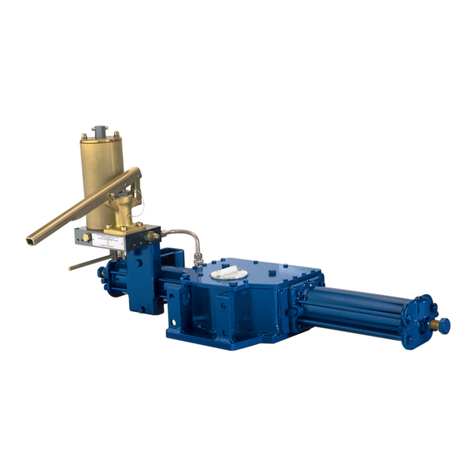
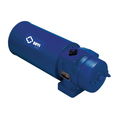
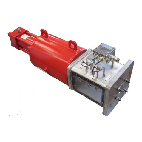
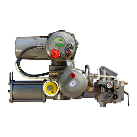
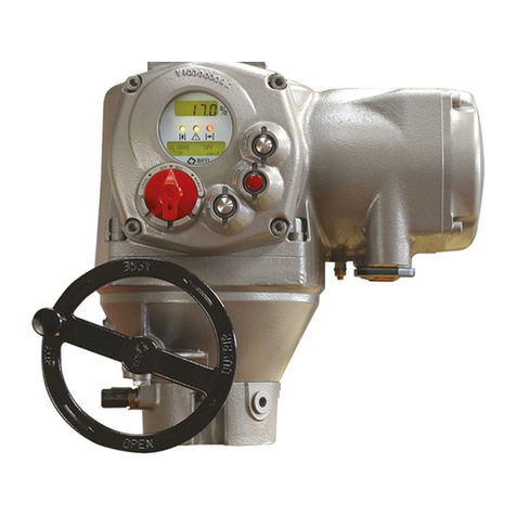
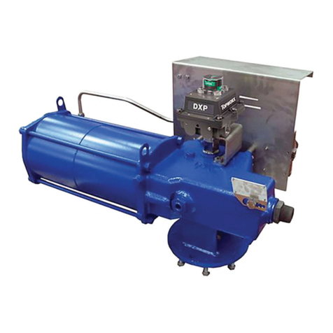
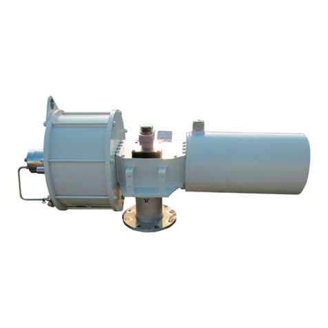
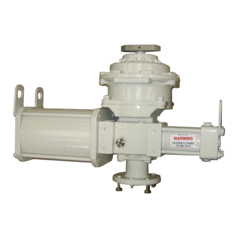
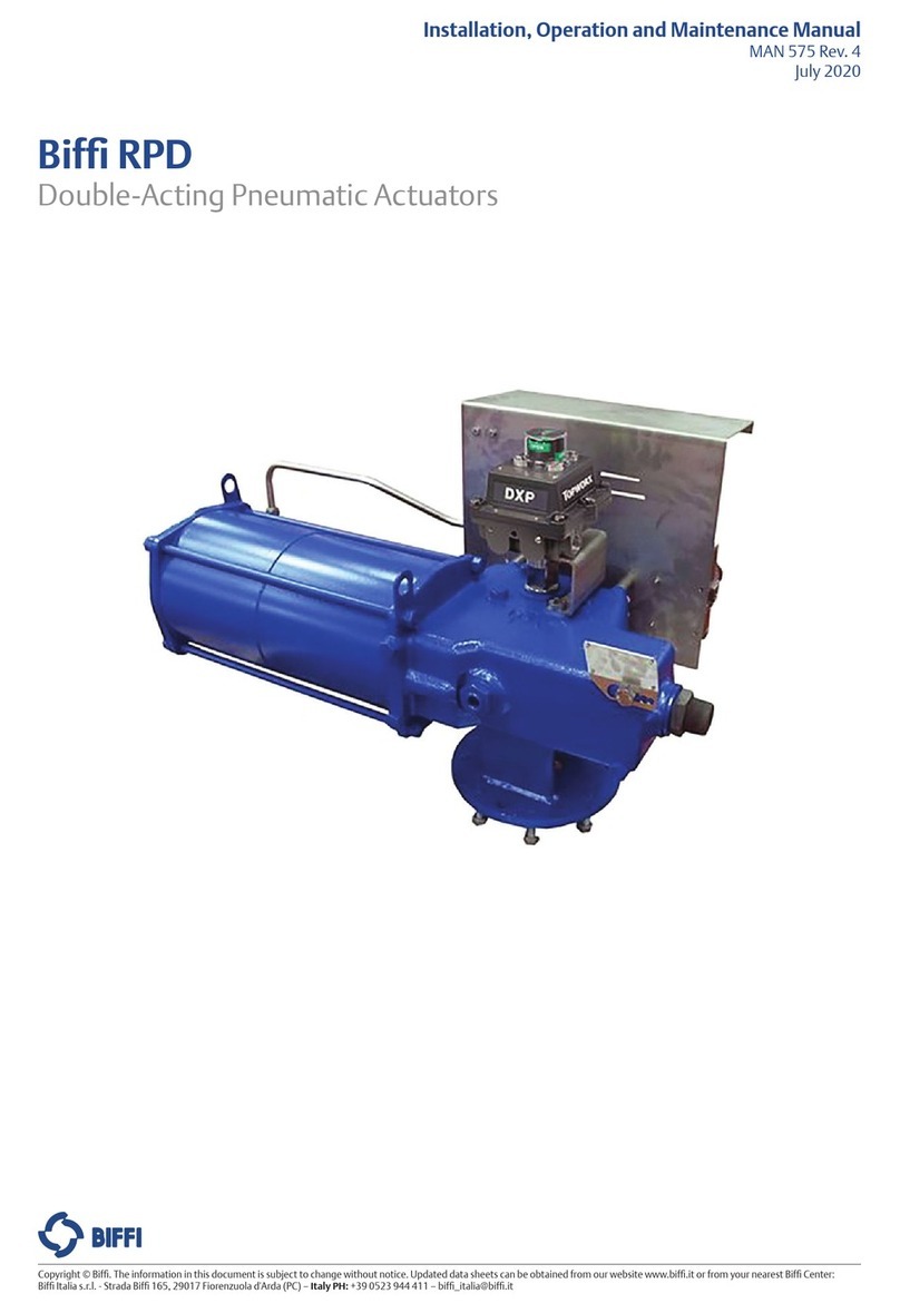
BIFFI EHO User manual

Installation, Operation and Maintenance Manual
VCIOM-15345-EN Rev. 1
February 2022
Bif EHO (Electro-Hydraulic Operated)
Spring-Return Actuator
Copyright © Bif. The information in this document is subject to change without notice. Updated data sheets can be obtained from our website www.bif.it or from your nearest Bif Center:
Bif Italia s.r.l. - Strada Bif 165, 29017 Fiorenzuola d'Arda (PC) – Italy PH: +39 0523 944 411 – bif_italia@bif.it

Installation, Operation and Maintenance Manual
VCIOM-15345-EN Rev. 1
Revision Details
February 2022
Revision Details
Revision Date Description Prepared Checked Approved
1 February 2022
0December 2020 Document release Toscani Callegari Oreci
Revision Details

i
Installation, Operation and Maintenance Manual
VCIOM-15345-EN Rev. 1
Table of Contents
February 2022
Table of Contents
Table of Contents
Section 1: Introduction
1.1 Scope............................................................................................................ 1
1.2 General Information...................................................................................... 1
1.3 Safety Information ........................................................................................ 3
1.4 Abbreviation Denitions ............................................................................... 4
Section 2: Installation
2.1 Preparation ................................................................................................... 5
2.2 Valve Preparation.......................................................................................... 6
2.3 Actuator Preparation..................................................................................... 6
2.4 Lifting the Bif EHO Actuator ........................................................................ 7
2.5 Installing the Bif EHO Actuator on the Valve .............................................. 10
2.6 Setting the Stroke Limit Stops ..................................................................... 11
2.7 Hydraulic Fluid ............................................................................................ 12
2.8 Accumulator (Optional) .............................................................................. 13
Section 3: Electrical Connections
3.1 Remove Separate Terminal Chamber (STC) Cover........................................ 18
3.2 Sealing Cable/Conduit Entries ..................................................................... 19
3.3 Recommended Terminal Connections......................................................... 19
3.4 Separate Terminal Chamber (STC) Connections........................................... 20
3.5 Replace Terminal Chamber Cover ................................................................ 20
3.6 External Earth/Ground Connections............................................................ 20
3.7 Discrete Controlled Inputs Connection........................................................ 21
Section 4: Set-up/Start-up Procedure
4.1 Preparation ................................................................................................. 23
4.2 Initial Check of the Unit............................................................................... 24
4.3 Initial Connections ...................................................................................... 24
4.4 Handpump Operation................................................................................. 24
4.5 Hydraulic Test ............................................................................................. 25
4.6 Check Rotation ........................................................................................... 26
4.7 Self-Calibration ........................................................................................... 27
4.8 Limit Switch Adjustment (Optional) ............................................................ 28
4.9 Function Test with Local Controls................................................................ 31
4.10 Other Options............................................................................................. 32
Section 5: Communication Protocols
5.1 Modbus RTU ............................................................................................... 33
5.2 HART .......................................................................................................... 35
5.3 FOUNDATION™ Fieldbus............................................................................. 36

ii
Table of Contents
February 2022
Installation, Operation and Maintenance Manual
VCIOM-15345-EN Rev. 1
Table of Contents
Section 6: Operation
6.1 Hydraulic Power System.............................................................................. 37
6.2 Fluid Reservoir............................................................................................. 37
6.3 Main Components and Options................................................................... 37
6.4 Functional Description ................................................................................ 40
6.5 Actuator Operation Channels...................................................................... 42
Section 7: Local Display Module (LDM)
7.1 Positions and Functions of Selector Knob .................................................... 44
Section 8: Customizing Bif EHO Settings
8.1 Entering the Setup Menu............................................................................. 45
8.2 Change Settings.......................................................................................... 47
8.3 Find Setting Feature .................................................................................... 50
8.4 EHO Conguration Menu ............................................................................ 53
8.5 Alarms ........................................................................................................ 67
Section 9: Troubleshooting
Troubleshooting....................................................................................................70
Section 10: Hazardous Area Classication and SIL Certication
Hazardous Area Classication and SIL Certication.................................................71
Section 11: General Wiring Diagram
11.1 Sample Wiring Diagram .............................................................................. 72
11.2 Applicable Operating Diagram.................................................................... 74
Section 12: Maintenance
12.1 Storage Procedures..................................................................................... 85
12.2 Service Interval ........................................................................................... 85
12.3 Lubrication Requirements ........................................................................... 86
12.4 Recommended Annual Inspection............................................................... 86

Installation, Operation and Maintenance Manual
VCIOM-15345-EN Rev. 1 February 2022
Introduction 1
Section 1: Introduction
1.1 Scope
This manual is offered as a guide to be used along with locally approved and safe practices
to install, operate, service and maintain the Bif EHO Actuator. Carefully follow the
instructions in this manual and make sure you install the actuator correctly and according
to your requirements.
1.2 General Information
1.2.1 Overview
The Bif EHO is a self-contained, quarter-turn, valve actuator that combines proven
technologies from Emerson’s Actuation Technologies. The actuator has been designed
for critical shutdown applications where reliability is crucial. The Bif EHO utilizes a
dependable spring-return actuator for the fail-safe stroke combined with an integral
hydraulic power pack and electronic control module.
The Bif EHO accepts a wide range of single-phase, three-phase or DC power sources.
A hydraulic handpump can be used to stroke the actuator during commissioning or in the
event of an emergency power loss.
Electronic modules are contained within an explosion proof, IP68 enclosure and all
electronic components are isolated from the customer connection terminals.
The Bif EHO provides a compact design with actuator and control components that have
been eld proven for decades in critical service applications.
The Bif EHO is designed for modulating ESD applications and comes with alert, alarm,
diagnostic, and self-calibration features.

February 2022
Installation, Operation and Maintenance Manual
VCIOM-15345-EN Rev. 1
Introduction2
Section 1: Introduction
1.2.2 Product Attribute
• Easy installation – Bif™ EHO actuator is a totally self-contained system and
designed for compactness and adaptable to new or existing valves
• Bif OLGA-H/OLGAS-H hydraulic double-acting or spring-return fail-safe actuator
• Bif RPHD/RPHS hydraulic double-acting or spring-return fail-safe actuator
• EIM™ electronics and communication technology
• Multiple input power options with either AC or DC
• Local lockable Remote/Local/Ofine selector switch
• Local open/close selector knob
• Partial stroke test
• Fast speed of operation to fail-safe position if required
• Emergency shutdown – independent safety circuits and solenoid valve
• Dual sealed Separate Terminal Chamber, allows installation wiring to be performed
or fuses to be replaced without exposing control components to hostile
environmental conditions
• Control enclosure is made of low-copper aluminum alloy, salt resistant also rated
for IP68 ingress protection
• Hydraulic handpump manual override
• Accumulators (optional)
• Operating pressures up to 3000 psi with standard components
• Easy control over actuator stroking speeds – The stroking speed is controlled
through adjustable hydraulic ow control valves. This enables eld personnel to
easily adjust actuator stroking speed to comply with eld requirements
• Communication support through Modbus, HART, Foundation Fieldbus
• Supports conguration, monitoring, and diagnostics with DCMlink
• Over 15 alerts and alarms
• Diagnostics and self-calibration features
• Modulate with 4 - 20 mA analog input

Installation, Operation and Maintenance Manual
VCIOM-15345-EN Rev. 1 February 2022
Introduction 3
Section 1: Introduction
1.3 Safety Information
Safety notices in this manual detail precautions the user must take to reduce the risk of
personal injury and damage to the equipment. The user must read these instructions in
their entirety. Failure to observe these safety notices could result in serious bodily injury,
damage to the equipment, void of the warranty. Take special notice of all tags, warning
labels and instructions presented on the actuator. These may provide more specic and
signicant information regarding the actuator than this general manual.
It is the responsibility of the user to ensure proper safety practices are utilized. Always
take necessary precautions and use proper protective equipment when dealing with
compressed gasses, compressed hydraulic uid, pinch points and electricity.
Safety notices are presented in this manual in three forms (Warning, Caution and Notice)
as follows:
! WARNING
Alerts user of potential danger; failure to follow the warning notice could result in serious
personal injury or death.
! CAUTION
Identies precautions the user must take to avoid personal injury or equipment damage.
NOTICE
Highlights information critical to the user’s understanding of the Bif EHO valve actuator
installation or operation.
Refer to Bif OLGA-H, OLGAS-H for Hydraulic RPHD, and RPHS Installation, Operation and
Maintenance Manual for additional details. If requested, the cover holes are protected by a
weather protection Loctite SI 5366 (or equivalent transparent silicon base product), easily
removable with a screw if requested special service maintenance. After the reassembly
activity, remember to rell the weather protection product in the holes.

February 2022
Installation, Operation and Maintenance Manual
VCIOM-15345-EN Rev. 1
Introduction4
Section 1: Introduction
1.4 Abbreviation Denitions
Abbreviations used in this manual and their denitions are listed in Table 1.
Table 1. Abbreviation Denitions
Abbreviation Denition
IOM Installation Operation Manual
ESD Emergency Shutdown
FS Fail-Safe
SA Single-Acting
DA Double-Acting
MAWP Maximum Allowable Working Pressure
MOP Maximum Operating Pressure
STC Separate Terminal Chamber
PST Partial Stroke Test
FST Full Stroke Test
LDM Local Display Module
RDM Remote Display Module
CBM Circuit Breaker Module
PCB Printed Circuit Board
LS Limit Switch
PS Pressure Switch
NC Normally Closed
NO Normally Open
CCW Counterclockwise
CW Clockwise
OL Overload
PPE Personal Protective Equipment
GA General Arrangement Drawing
SOV Solenoid Valve
NO Normally Open
NC Normally Closed
CAM Communication Adapter Module

Installation, Operation and Maintenance Manual
VCIOM-15345-EN Rev. 1 February 2022
5Installation
Section 2: Installation
2.1 Preparation
2.1.1 Delayed Usage
If for any reason the actuator is not to be installed immediately, Bif recommends the
following procedures. Failure to comply, with recommended procedures, could lead to
actuator malfunction and possibly void the warranty. For storage procedures exceeding
one year, consult Bif for further recommendations.
As shipped from the factory, the Bif EHO actuator is an inherently weatherproof unit,
providing that all compartment covers and cable entry plugs remain intact.
The actuator should be immediately stored in a clean, dry warehouse, free from vibration
and rapid temperature changes, until it can be installed and energized.
If the actuator must be stored outside, store it off of the ground at an elevation sufcient
to prevent it from being immersed in water or buried in snow. Check for any unpainted
or exposed metal surfaces and make sure they are protected with a coating of grease to
prevent any corrosion. Cover the actuator to prevent damage from site debris.
2.1.2 Tools and Materials Required
To complete these procedures, you will need the following documentation for the
Bif EHO Actuator and the items are indicated in Table 2.
• General Arrangement Drawing
• Bill of Material
• Hydraulic System Schematic
• System Wiring Diagram
Table 2. Tools and Material Requirements
Tools and Material Requirements
Primary Power Source for the Bif EHO
(check the Bif EHO System Electrical Diagram for requirements)
Supplemental quantity of hydraulic uid, if needed
(See Section 2.7, Hydraulic Fluid and Bif EHO specication, for required uid type)
Nitrogen Source (if an Accumulator is supplied with the Bif EHO)
Hand Tools: complete complement of open end (SAE and metric) wrenches, screwdrivers Philips
and at blade and a set of hex wrenches
Chains and lifting straps that are inspected and certied for the weight of the Bif EHO Actuator
(check shipping weights)
Sealant for all cable and conduit entries (approvable by the National Electric Code or your country
standard and applicable local codes)

February 2022
Installation, Operation and Maintenance Manual
VCIOM-15345-EN Rev. 1
6 Installation
Section 2: Installation
2.2 Valve Preparation
2.2.1 Remove Valve Gearing if equipped.
2.2.2 If valve is equipped with stops, remove valve stem extension housing. Examine
the valve stops to ensure no foreign material is present that would restrict normal
travel of the valve. Some valves are equipped with inspection ports in the valve
housing for ease in examining the stops.
2.2.3 Check alignment of stem key slot to the position of the valve. Normally with the
valve in the open position, the key slot is in line with the run of the pipeline. With
the valve in the closed position, the key slot should be 90° to the run of the valve.
2.2.4 The Bif EHO Actuator may be mounted to the valve at any time regardless of
whether or not the valve is under pressure.
2.3 Actuator Preparation
2.3.1 Once the Bif EHO Actuator is uncrated and cleaned for installation, check to
ensure there will be no interference with piping or other structure when the
actuator is properly mounted to the valve.
NOTICE
At this point, check to see that when the actuator is mounted to the valve and in its
nal orientation, the outboard end of the power cylinder positioned below the Hydraulic
Reservoir Breather. If this is not possible, contact Bif for further instructions on piping
to elevate the breather. Refer also to standard manual of relevant Bif Actuator, RPH and
OLGA-H series.
2.3.2 Check that all mounting materials such as fasteners, adapters, brackets etc. are on
hand and ready for use.
2.3.3 Check the actuator and valve to see that they are in the same relative position,
that is either open or closed. If the actuator has to be moved, use the handpump
provided. For handpump operation, remove the plug in the reservoir and install
the breather (refer to Section 4.4, Handpump Operation).
2.3.4 If the unit is equipped with an optional piston style accumulator, it is critical that
the accumulator is precharged with nitrogen prior to operating the equipment.
Refer to Section 2.8 for precharging instructions.
NOTICE
All spring-return Bif EHO Actuators are supplied with a thermal compensating device
for protection from thermal-expansion of the hydraulic uid. This thermal compensating
device is preset at the factory and will not need servicing during installation or start-up of
the actuator.

Installation, Operation and Maintenance Manual
VCIOM-15345-EN Rev. 1 February 2022
7Installation
Section 2: Installation
NOTICE
Failure to precharge the accumulator may cause the accumulator to not function properly.
! CAUTION
Be aware, while preparing to and lifting the actuator, the Thermal Compensating Device
contains high-pressure nitrogen. Use care not to damage the Thermal Compensating
Device or its attachments.
2.4 Lifting the Bif EHO Actuator
NOTICE
All Bif EHO OLGA-H/OLGAS-H-Series or RPHD/RPHS-Series Considerations
When handling any Bif EHO OLGA-H/OLGAS-H-Series or RPHD/RPHS-Series be
aware of tubing, accessories, handpump, accumulators, local display module and
control enclosures. Straps and chains can become entangled and cause damage to these
components. Never use chains on the spring cartridge as it may warp and cause the
actuator not to function correctly or may cause personal injury.
NOTICE
Do not use hydraulic tubing and electrical cable for lifting.
! CAUTION
Be sure to use appropriately rated crane/hoist and straps/chains to raise and lower
the actuator.

February 2022
Installation, Operation and Maintenance Manual
VCIOM-15345-EN Rev. 1
8 Installation
Section 2: Installation
2.4.1 OLGA-H/OLGAS-H-Series Actuators
2.4.1.1 Horizontal Pipeline Vertical Stem
The OLGA-H/OLGAS-H series actuators mounting on a horizontal pipeline with
a vertical valve stem should be supported using the 3 lifting point (two on the
scotch yoke mechanism and one on the spring container). A strap may be attached
to the stabilization tab on the spring module to balance the unit while lifting.
The weight of the actuator must be supported by the proper lifting point, not the
stabilization tab, see Figure 1.
Figure 1
! CAUTION
Never lift the actuator with a valve attached. Always handle actuator/valve assemblies by
attaching lifting equipment to the valve only.
! CAUTION
Please note that other mounting positions are available, in case of needing please contact
the factory.

Installation, Operation and Maintenance Manual
VCIOM-15345-EN Rev. 1 February 2022
9Installation
Section 2: Installation
2.4.2 RPHD/RPHS-Series Actuators
2.4.2.1 Horizontal Pipeline Vertical Stem
The RPHD/RPHS series actuators mounting on a horizontal pipeline with a vertical
valve stem should be supported using the 4 lifting point (two on the cylinder and
two on the spring container). The weight of the actuator must be supported by
the proper lifting point, not the stabilization tab, see Figure 2.
Figure 2
! CAUTION
Never lift the actuator with a valve attached. Always handle actuator/valve assemblies by
attaching lifting equipment to the valve only.
! CAUTION
Please note that other mounting positions are available, in case of needing please contact
the factory.

February 2022
Installation, Operation and Maintenance Manual
VCIOM-15345-EN Rev. 1
10 Installation
Section 2: Installation
2.5 Installing the Bif EHO Actuator on the Valve
The actuator will be bolt-mounted directly to a bracket or adaptor that will be bolted
securely to the mounting ange top works of the valve.
2.5.1 Check to see that the dimensions of the bracket or adaptor are suitable for use
with the valve mounting ange and stem.
2.5.2 Check valve direction of rotation and the actuator direction of rotation to see they
match (for example: CW = close, CCW = open).
2.5.3 Check to see the actuator and valve are in the same relative position
(see Section 2.3.3).
2.5.4 Check all mounting surfaces, they must be clean and free of debris to permit
proper t up.
2.5.5 Prior to mounting, grease the coupling bore and the bore of the actuator.
NOTICE
Do not apply grease to the mounting ange surfaces on the valve or the adaptor.
2.5.6 Install the stem key and grease it (keys may be held in place with tape).
2.5.7 Install the coupling onto the stem and stem key.
2.5.8 Install the coupling key and grease it.
2.5.9 Carefully align the coupling and key to the bore and keyway in the actuator and
slide the actuator onto the coupling until the adapter (bracket) bottoms out on
the valve bonnet.
NOTICE
Ensure the adapter seats out on the valve bonnet, without interference, before
installing fasteners.
2.5.10 Use the required fasteners to rmly attach the adapter to the valve bonnet.
Tighten the fasteners to their manufacturer’s recommended maximum torque
(dry or lubricated).

Installation, Operation and Maintenance Manual
VCIOM-15345-EN Rev. 1 February 2022
11Installation
Section 2: Installation
2.6 Setting the Stroke Limit Stops
2.6.1 The Bif OLGA-H/OLGAS-H and RPHD/RPHS Actuator is provided with bidirectional
travel stops allowing 80° to 100° total travel (+/- 5° adjustment at each end of the
90° stroke).
2.6.2 Actuators are shipped from the factory with the travel stops adjusted for
approximately 90° rotation. Generally, it is necessary to make slight travel
stop adjustments once the actuator is installed on the valve. Refer to the valve
manufacturer's recommendations for specic requirements.
2.6.3 When the valve has internal stops, the actuator stops must be set so that the load
is applied to them, not the valve stops.
2.6.4 If adjustment is required, use the handpump to move the actuator off the
stop at the Fail-Safe Position before attempting to turn the adjusting screw
(refer to Section 4.4, Handpump Operation).
! CAUTION
Do not adjust actuator’s stop at the Fail-Safe Position, with the spring force against the
stop. Always use the handpump to move the actuator off the stop before attempting to
turn the adjusting screw.
2.6.5 With the Fail-Safe Position stop set, use the handpump to move the actuator to
the other end of the stroke and check the stop position. If adjustment is required,
slowly open Manual Bypass Valve (Lockable) (19) just enough to allow the actuator
to spring-return off the stop before adjusting.

February 2022
Installation, Operation and Maintenance Manual
VCIOM-15345-EN Rev. 1
12 Installation
Section 2: Installation
2.7 Hydraulic Fluid
Bif Electro-Hydraulic Operated actuators are shipped with the reservoir lled to operation
level. Before commissioning and periodically afterwards, check to see the uid level is
correct. The oil ll cap is provided with a dipstick marked with a green and a red mark.
When the optional accumulator is drained of uid and the actuator is at Fail-Safe Position,
the oil should be at the green mark. The reservoir also has a sight gauge for the purpose
of seeing uid is present. Should uid need to be added or replaced, use only factory
approved hydraulic uid.
This specication covers hydraulic uids which are approved by engineering for use in
Bif Electro-Hydraulic Operated actuator in a temperature range from -40 °C to 60 °C
(-40 °F to 140 °F).
2.7.1 Approved Fluids
Standard Fluid [use with -29 °C to 60 °C (-20 °F to 140 °F) applications]
— AGIP ARNICA 22
— ConocoPhillips Megaow™ AW HVI Hydraulic Oil
— 22 Shell Tellus S2 V 22
— Mobil DTE 10 Excel™ 22
Low Temperature Fluid [use with -40 °C to 60 °C (-40 °F to 140 °F) applications]
— Shell AEROSHELL 41 Fluid
— Mobil Univis™ HVI 13
Although other brands of uid matching the same specications may be used, to maintain
the warranty and ensure trouble-free operation, always check with the factory before
substituting any other uid.

Installation, Operation and Maintenance Manual
VCIOM-15345-EN Rev. 1 February 2022
13Installation
Section 2: Installation
2.8 Accumulator (Optional)
2.8.1 Introduction
The Bif EHO Actuator may be equipped with an accumulator for modulating valve
control or to enable manual operation of the actuator if there is a loss of electrical power.
Accumulators always have the nitrogen pressure drained for shipping.
When using this procedure, refer to the Bif EHO Actuator General Arrangement drawing
and Hydraulic Schematic for the unit being worked on. Schematics shown in this document
are for illustration purposes only.
! WARNING
This unit contains high-pressure hydraulic uid and nitrogen gas. Exercise caution when
performing any type of maintenance. Wear proper safety attire and required personal
protective equipment, including safety glasses.
2.8.2 Accumulator Pre-charge
a. Locate Isolation Valve (25) (Nitrogen Blow Down and Fill) for the Customer
Nitrogen Fill Connection, called out on the General Arrangement Drawing
and Hydraulic Schematic (see Figure 3).
b. Close the Isolation Valve (25) (Nitrogen Blow Down and Fill) and remove
the pipe plug from the adaptor.
NOTICE
The Adaptor is tapped with a 1/4-NPTF thread.
c. Ensure 3-way Isolation Valve (22) is turned fully counterclockwise.
d. Slowly open Isolation Valve (Accumulator drain) (24) and drain all the uid
back to the reservoir.
e. Connect a nitrogen supply to the Customer Nitrogen Fill Connection at
Isolation Valve (25) (Nitrogen Blow Down and Fill).
f. Open the Isolation Valve (25) (Nitrogen Blow Down and Fill) and charge
the Accumulator, to the pre-charge pressure as specied by the Pressure
versus Temperature Graph on the General Arrangement Drawing.

February 2022
Installation, Operation and Maintenance Manual
VCIOM-15345-EN Rev. 1
14 Installation
Section 2: Installation
NOTICE
For temperatures, which do not appear on the graph, the formula to calculate the
pre-charge pressure shown on the General Arrangement Picture Assembly should be used.
NOTICE
Recheck the pre-charge pressure after a time interval sufcient to insure the nitrogen
pressure is equal to the ambient temperature (a minimum of 4 hours). Adjust the
pre-charge pressure as required to conform to the Pressure versus Temperature graph.
g. After the nitrogen lling is complete, close the Isolation Valve (25)
(Nitrogen Blow Down and Fill).
h. Disconnect the nitrogen supply and remove the female pipe adaptor from
Isolation Valve (25) (Nitrogen Blow Down and Fill).
i. Install the straight thread plug and O-ring, shipped as an accessory, into
Isolation Valve (25) (Nitrogen Blow Down and Fill).
NOTICE
The straight thread plug must be installed, after lling is complete, to prevent accidental
leakage of nitrogen from Isolation Valve (25) (Nitrogen Blow Down and Fill).
j. Close Isolation Valve (24).

G
C
H
F
B
D
I
E
A
Installation, Operation and Maintenance Manual
VCIOM-15345-EN Rev. 1 February 2022
15Installation
Section 2: Installation
TO MANIFOLD
POWER PORT
TO CYLINDER
Figure 3 Typical EHO Optional Accumulator System
Table 3. Typical EHO Optional Accumulator System
Part Number Part Name
AReservoir
BAccumulator
CNitrogen Relief Valve
D3-way Isolation Valve
EIsolation Valve (Accumulator Drain)
FIsolation Valve (Nitrogen Blow Down and Fill)
GNitrogen Pressure Gauge
H Nitrogen Gauge Isolation Valve
ISpeed Control

February 2022
Installation, Operation and Maintenance Manual
VCIOM-15345-EN Rev. 1
16 Installation
Section 2: Installation
2.8.3 Pre-charge Verication
Check the nitrogen pre-charge in the accumulator periodically to ensure the accumulator is
at full potential. Follow the steps below and record nal readings for reference.
a. Shut off the hydraulic power supply to the accumulator.
b. Ensure 3-way Isolation Valve (D) is turned fully counterclockwise.
c. Slowly open Isolation Valve (Accumulator drain) (E) and drain all the uid
back to the reservoir.
d. Read the pressure at the nitrogen pressure gauge (G) and compare it to
the Oil/Temperature Chart shown on the General Assembly Drawing for
the job being checked.
e. If the pre-charge is low, add nitrogen to increase the pressure to the
requirements listed on the GA Oil/Temperature Chart. See Section 2.8.2,
Accumulator Pre-charge, if the pre-charge is high relieve pressure to equal
the GA Oil/Temperature Chart.
f. Record Information below.
g. With bypass valve closed, reconnect the hydraulic power supply and bring
the accumulator back up to full pressure.
h. Check the entire nitrogen circuit for leaks using a liquid leak detector such
as Snoop (manufactured by Swagelok). As the unit is self-contained, only
a zero leak rate is acceptable. Corrective action must be taken for any
leaks found.
2.8.4 Check Thermal Compensating Device
The nitrogen pre-charge should be checked in the Thermal Compensating Device annually.
To accomplish this, use a commercially available charging kit and follow the instructions
supplied with the kit.
! WARNING
This unit contains high-pressure hydraulic uid and nitrogen gas. Exercise caution when
performing any type of maintenance. Wear proper safety attire and required personal
protective equipment, including safety glasses. Ensure the accumulator has been drained
of all hydraulic and nitrogen pressure before attempting any repair.
Table of contents
Other BIFFI Controllers manuals

BIFFI
BIFFI ALGA - EAC User manual

BIFFI
BIFFI ICON3000 Series User manual

BIFFI
BIFFI ALGAS-QA Series Manual

BIFFI
BIFFI GILS User manual

BIFFI
BIFFI HLAS User manual

BIFFI
BIFFI GIGS 0.3 User manual

BIFFI
BIFFI HLAS User manual

BIFFI
BIFFI OLGAS-H User manual

BIFFI
BIFFI FCB Series User manual

BIFFI
BIFFI HLAS-C Series User manual
Popular Controllers manuals by other brands

Fairplay
Fairplay MP-70 Series quick reference

C.P. Electronics
C.P. Electronics GESM-AC installation guide

Light Symphony
Light Symphony LS30505SCC instructions

KeriSystems
KeriSystems PXL-510 quick start guide

Hobby-Wing
Hobby-Wing XERUN XR10 STOCK SPEC 1S user manual

Samwontech
Samwontech TEMP1000 Series Communications manual