19
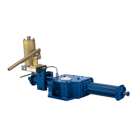
Replacement of seals for actuators with Biffi
manual hand-pump (see figure 27)
If there are leaks in the hydraulic cylinder or a
malfunction in the mechanical components, or
in case of scheduled preventive maintenance,
the actuator must be disassembled and
seals must be replaced with reference to the
sectional drawing and adopting the following
procedures:
1� Remove the nuts (item 16) and the washers
(item 15) from the tie rods (item 10) at the
end flange (item 13) side�
2� Slide off the end flange and the tube
(item12)�
3� Remove the screws (item 2-fig� 26) and the
cover (item 1-fig� 26)�
4� Unscrew the piston rod (item 6) threaded
end from the adaptor bush (item 32-fig� 26)
of guide block (item 14-fig� 26)�
5� Slide off the piston rod from the head flange
(item 2)�
6� Disassemble the head flange from the
mechanism housing (item 8-fig� 26) by
removing the screws (item 7- fig� 26) only
if the gasket (item 39-fig� 26) has to be
replaced because damaged�
Seals replacement
Prior to reassemble check that the actuator
components are in good conditions and clean�
Lubricate all the surfaces of the parts, which
move in contact with other components, by
recommended grease� If the O-ring must be
replaced, remove the existing one from its
groove, clean the groove carefully and lubricate
it with protective oil or grease film� Assemble
the new O-ring into its groove and lubricate it
with a protective oil or grease film�
1� Replace the O-rings (3) of the head flange
(2)�
2� Replace the O-ring (3) of the end flange (13)�
For replacement of piston rod seal ring (4) and
of the O-ring (5) proceed as follows:
1� Remove the existing PTFE seal ring (4) and
the O-ring (5) from their groove�
2� Clean the groove carefully and lubricate it
with a protective oil or grease film�
3� Assemble the new O-ring into its groove and
lubricate it with a protective oil or grease
film�
4� Assemble the new PTFE seal ring (4) into
the flange groove, on the rubber O-ring (5),
by bending it: take care that the bending
radius is as large as possible to avoid
damaged the seal� Then enlarge the seal
ring with your fingers so as to restore its
round shape: pay attention not to utilize any
tools, which can damage the seal ring�
To replace the piston dual-seal ring (9) proceed
as follows :
1� Remove the existing dual-seal ring (9) from
its groove�
2� Clean the groove carefully and lubricate it
with a protective oil or grease film�
3� Assemble the new dual-seal ring (9) by
introducing one side of it into the groove
and then enlarge it with your fingers so as
to introduce it into the groove: take care
to enlarge it uniformly without any tools
which could possibly damage it� The elastic
memory of the kind of PTFE type the seal
ring is made of allows the ring to shrink
back to its previous dimension after a short
time�
4� If the O-ring (17) has to be replaced,
measure the protrusion of the stop screw
(11) with reference to the end flange (13)
surface, so as to be able to easily restore
the setting of the actuator mechanical
stop in the open valve position, once
the maintenance procedures have been
completed�
5� Loosen the protection cover (14) and
unscrew the stop screw (11) until it is
removed�
6� Replace the O-ring (17) from the stop screw
cover (14)�
7� Screw the stop screw into the threaded hole
of the end flange until it reaches its original
position (the same protrusion with reference
to the flange surface)�
8� Tighten the protection cover (14)�
Reassemble
1� Assemble the new gasket (item 39-fig�26)
after cleaning the surfaces of housing
(item8-fig� 26) and head flange (item 2)
which are in contact�
2� Assemble the head flange and tighten the
screws (item 7- fig� 26) to the recommended
torque�
3� Clean and lubricate the piston rod (item 6)
surface, particularly that of the bevel, with
a protective oil or grease film and introduce
it into the head flange hole, taking care not
to damage the PTFE seal ring (item 4): the
piston rod bevel has to enlarge smoothly the
seal ring�
4� Carefully clean the threaded end of the
piston rod and the threaded hole of the
adaptor bush (item 32-fig� 26) of guide block
(item 14-fig� 26)� Spread some sealant
LOCTITE 452, or equivalent, on the rod
threaded end and screw into the adaptor
bush threaded hole and tighten�
5� Carefully clean the inside of the tube
(item12) and check that the entire surface,
particularly that of the bevels, is not
damaged� Lubricate with protective oil or
a grease film the tube inside surface and
the bevels at the ends� Slide the tube onto
the piston taking cares not to damaged the
dual-seal ring (item 9): the tube bevel has to
smoothly compress the seal ring�
6� Take care also not to damage the head
flange O-ring (item 3)�
7� Assemble the end flange (item 13) by
centring it on the inside diameter of the
tube, taking cares not to damage the O-ring
(item 3)�
8� Assemble the washers (item 15) and the
nuts (item 16) onto the tie rods (item 10)�
Tighten the nuts to the recommended
torque, alternating between opposite
corners�
9� Restore a generous coating of grease on
the contact surfaces of the yoke (item 11-
fig� 26) and the bushings (item 13-fig� 26),
on the yoke grooves, on the sliding blocks
(item5-fig� 26), on guide bar (item 9-fig� 26)�
10� Assemble the new gasket (item 39-fig� 26)
after cleaning the surfaces of the housing
(item 8-fig� 26) and cover (item 1-fig� 26)
11� Lubricate with protective oil or grease the
O-ring (item 34-fig� 26)�
12� Assemble the cover (item 1-fig� 26) and the
screws (item 2-fig� 26)� Tighten the screws
to the recommended torque�
IMPORTANT
AFTER MAINTENANCE OPERATIONS CARRY OUT
A FEW ACTUATOR OPERATIONS TO CHECK THAT
ITS MOVEMENT IS REGULAR AND THAT THERE
IS NO AIR LEAKAGE THROUGH THE SEALS.
BIFFI OLGA-H HIGH PRESSURE DOUBLE ACTING HYDRAULIC ACTUATOR
INSTALLATION, OPERATION AND MAINTENANCE MANUAL


