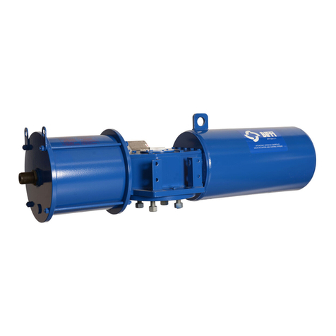
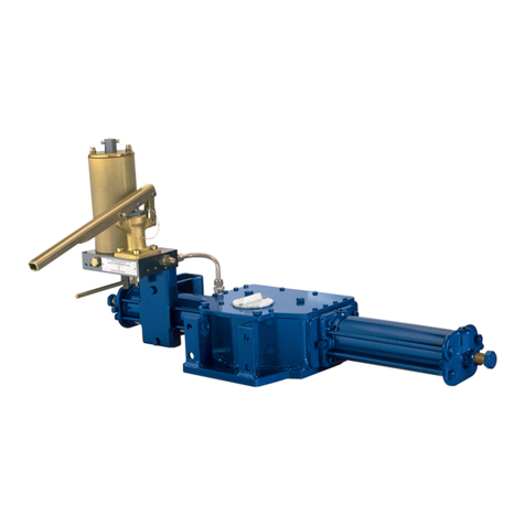
BIFFI TPS Series User manual

TPS Series
Single acting pneumatic actuator for quarter turn
applications
BIFFI ITALIA srl. - ITALIA – Strada BIFFI 165 - 29017 Fiorenzuola d’Arda (PC)
Phone +39 0523 94 44 11 – Fax +39 0523 94 18 85
TURN PNEUMATIC – TPS Series
Compact pneumatic actuator – single acting
MAN 714
Use and maintenance manual
Drawn up according to CE Directives
- Translation of the original instructions -
Rev. 03 – Edition 07.2019


DOCUMENT REVISION TABLE
Rev.
Date
Description
Prepared
Checked
Approved
00
07/2013
Document release
Comelli
Comelli
Vigliano
01 09/2013 Supplement: ATEX safety
provisions
Comelli Comelli Vigliano
02 08/2016
TPS 0.A model added
Comelli Comelli Vigliano
Standard ISO 5211 interface
(extract from document SCN
7976) updated
Comelli Comelli Vigliano
Custom Alga/Algas
interchangeable interface
(extract from document SCN
7975) updated
Comelli Comelli Vigliano
03 16/07/2019 Updated actuator data-plate
and suggested grease for
lubrication
Ermanni Orefici Vigliano
Before carrying out any operation with the actuator or any maintenance
intervention, all the instructions, procedures and warnings described in this
Instruction Manual must be read and understood.
Furthermore, please refer to the confirmation documentation for further information
depending on the configuration of the pneumatic actuator referred to in the present
Instruction Manual.
- TO BE KEPT FOR FUTURE REFERENCE -


COMPACT PNEUMATIC ACTUATOR - TPS Series
Table of contents
MAN 714 TPS Series – Use and maintenance manual – Rev. 03 1
TABLE OF CONTENTS
1 GENERAL INFORMATION ...................................................................................... 1.1
1.1 Identification data of the Manufacturer .................................................................................................................. 1.1
1.2 Instruction manual identification data .................................................................................................................... 1.1
1.3 Requesting technical assistance ........................................................................................................................... 1.1
1.4 Spare parts ordering .............................................................................................................................................. 1.2
1.5 Intended use ......................................................................................................................................................... 1.2
1.6 Misuses ................................................................................................................................................................. 1.3
1.7 Limitation of use .................................................................................................................................................... 1.3
1.8 General safety provisions ...................................................................................................................................... 1.4
1.9 Limitation of liability ............................................................................................................................................... 1.4
1.10 Warranty ................................................................................................................................................................ 1.4
1.11 Regulatory reference framework ........................................................................................................................... 1.5
1.12 Demolition and disposal ........................................................................................................................................ 1.5
2 TECHNICAL DESCRIPTION ................................................................................... 2.1
2.1 Fields of application ............................................................................................................................................... 2.1
2.2 Identification data of the actuator .......................................................................................................................... 2.1
2.3 General safety provisions ...................................................................................................................................... 2.4
2.4 Safety provisions for installation in hazardous areas............................................................................................. 2.5
2.5 Actuator applications ............................................................................................................................................. 2.6
2.6 General description ............................................................................................................................................... 2.6
2.7 Main features ........................................................................................................................................................ 2.8
2.8 Options and configurations .................................................................................................................................... 2.9
2.9 Accessories ......................................................................................................................................................... 2.10
2.10 Reading and understanding the product ID code ................................................................................................ 2.10
2.11 Main components and materials ......................................................................................................................... 2.11
2.11.1 TPS 0.A Actuator ........................................................................................................................................................ 2.11
2.11.2 TPS 0.1 / 0.3 / 0.9 / 1.5 / 3 Actuators .......................................................................................................................... 2.12
2.11.3 TPS 6 Actuator ........................................................................................................................................................... 2.13
2.11.4 TPS 14 / 18 / 32 Actuators .......................................................................................................................................... 2.14
2.12 Technical data ..................................................................................................................................................... 2.15
2.12.1 General data ............................................................................................................................................................... 2.15

COMPACT PNEUMATIC ACTUATOR - TPS Series
chapter 1 - General information
2 MAN 714 TPS Series – Use and maintenance manual – Rev. 03
2.12.2 Overall dimensions, weights and estimated centre of gravity position ........................................................................2.16
2.13 Valve coupling interface (Top Mounting) ............................................................................................................ 2.18
2.14 Connecting the stem valve ................................................................................................................................. 2.23
2.15 Pneumatic interfaces (TPS 0.A / 0.1 / 0.3 / 0.9 / 1.5 / 3) ..................................................................................... 2.23
2.16 Pneumatic interfaces (TPS 6) ............................................................................................................................. 2.24
2.17 Pneumatic interfaces (TPS 14 / 18 / 32) ............................................................................................................. 2.25
2.18 Other interfaces, devices and accessories ......................................................................................................... 2.27
2.19 Minimum requirements for installing control, signalling and diagnostic devices on board the actuator .............. 2.28
3 HEALTH AND SAFETY PROVISIONS .................................................................... 3.1
3.1 Introduction ........................................................................................................................................................... 3.1
3.2 Duties of the Safety Officer ................................................................................................................................... 3.2
3.3 Duties of the staff interacting with the actuator ..................................................................................................... 3.2
3.4 Residual risks ....................................................................................................................................................... 3.3
3.5 Information on personal protective equipment (P.P.E.) ........................................................................................ 3.4
4 TRANSPORT AND HANDLING .............................................................................. 4.1
4.1 Transport of the actuator ...................................................................................................................................... 4.1
4.1.1 General information .......................................................................................................................................................4.1
4.2 Lifting the actuator ................................................................................................................................................ 4.2
4.2.1 Lifting points ..................................................................................................................................................................4.2
4.2.2 Codes of practice for lifting operations ..........................................................................................................................4.3
4.3 Actuator handling .................................................................................................................................................. 4.4
4.3.1 General handling provisions ..........................................................................................................................................4.4
5 RECEIPT AND INSTALLATION OF ACTUATOR ................................................... 5.1
5.1 Receipt and inspection ......................................................................................................................................... 5.1
5.2 Storage ................................................................................................................................................................. 5.1
5.3 Customer Duties ................................................................................................................................................... 5.2
5.4 Assembly procedures ........................................................................................................................................... 5.3
5.4.1 Assembly .......................................................................................................................................................................5.3
5.4.2 Pneumatic connections .................................................................................................................................................5.6
5.4.3 Electrical connections (if foreseen) ................................................................................................................................5.7
6 COMMISSIONING AND ADJUSTMENTS ............................................................... 6.1
6.1 Inspections prior to commissioning ....................................................................................................................... 6.1
6.2 Calibrating the angular stroke ............................................................................................................................... 6.2

COMPACT PNEUMATIC ACTUATOR - TPS Series
Table of contents
MAN 714 TPS Series – Use and maintenance manual – Rev. 03 3
7 BIFFI LIMIT SWITCH BOX (IF FITTED) .................................................................. 7.1
7.1 Calibration of Biffi limit switches (if fitted) .............................................................................................................. 7.1
7.1.1 Limit switch calibration procedure ................................................................................................................................. 7.2
7.1.2 Indicator reset procedure: ............................................................................................................................................. 7.3
8 ROUTINE MAINTENANCE ...................................................................................... 8.1
8.1 General information ............................................................................................................................................... 8.1
8.2 Monitoring and visual inspection activities ............................................................................................................. 8.2
8.3 Monitoring and visual inspection activities for SIL certification .............................................................................. 8.2
9 SUPPLEMENTARY MAINTENANCE ...................................................................... 9.1
9.1 General information about supplementary maintenance ....................................................................................... 9.2
9.2 Technical guidelines for replacing the pneumatic cylinder seals ........................................................................... 9.4
9.2.1 General description ....................................................................................................................................................... 9.4
9.2.2 Partial or total seal replacement ................................................................................................................................... 9.9
9.2.3 Disassembling the pneumatic cylinder ....................................................................................................................... 9.10
9.2.4 Replacing the seals .................................................................................................................................................... 9.14
9.2.5 Assembling the pneumatic cylinder ............................................................................................................................ 9.15
9.3 Information necessary for seal replacement ........................................................................................................ 9.18
9.4 Lubrication ........................................................................................................................................................... 9.20
10 SPARE PARTS ...................................................................................................... 10.1
10.1 Pneumatic cylinder seals (material: NBR) ........................................................................................................... 10.1
10.2 Pneumatic cylinder seals (Fluorosilicone material).............................................................................................. 10.2
11 TROUBLESHOOTING ........................................................................................... 11.1
12 DISMANTLING AND DISPOSAL ........................................................................... 12.1

COMPACT PNEUMATIC ACTUATOR - TPS Series
chapter 1 - General information
4 MAN 714 TPS Series – Use and maintenance manual – Rev. 03
INDEX OF FIGURES
F 2.1 – Rating plate .......................................................................................................................................................... 2.1
F 2.2 – Identification plate ................................................................................................................................................. 2.4
F 2.3 – Main components and materials – TPS 0.A ........................................................................................................ 2.11
F 2.4 – Main components and materials – TPS 0.1 / 0.3 / 0.9 / 1.5 / 3 ........................................................................... 2.12
F 2.5 – Main components and materials – TPS 6 ........................................................................................................... 2.13
F 2.6 – Main components and materials – TPS 14 / 18 / 32 ........................................................................................... 2.14
F 2.7 – TPS actuator dimensions .................................................................................................................................... 2.16
F 2.8 – Standard ISO 5211 interface .............................................................................................................................. 2.20
F 2.9 – Custom ISO 5211 interface ................................................................................................................................ 2.21
F 2.10 – ALGA/ALGAS interchangeable interface .......................................................................................................... 2.22
F 2.11 – Position of pneumatic interfaces ....................................................................................................................... 2.23
F 2.12 – Position of pneumatic interfaces ....................................................................................................................... 2.24
F 2.13 – Position of pneumatic interfaces ....................................................................................................................... 2.25
F 2.14 – Position of interfaces, devices and accessories ............................................................................................... 2.27
F 2.15 – Lower view with example of over pressure valve positioning ............................................................................ 2.27
F 2.16 – Detail of connection and coupling interface of valve status indicator device ..................................................... 2.28
F 4.1 – Lugs / Eyes for lifting the actuator only ................................................................................................................. 4.2
F 4.2 – Example of hook with safety latch......................................................................................................................... 4.3
F 5.1 – Example of coupling flange ................................................................................................................................... 5.3
F 6.1 – Stopper operation ................................................................................................................................................. 6.2
F 6.2 – Stopper operation ................................................................................................................................................. 6.3
F 6.3 – Stopper components ............................................................................................................................................. 6.4
F 7.1 – Stoppers: position adjustment .............................................................................................................................. 7.1
F 7.2 – Cam calibration ..................................................................................................................................................... 7.2
F 7.3 – Status indicator and roll pin .................................................................................................................................. 7.3
F 9.1 – Pneumatic cylinder seals ...................................................................................................................................... 9.4
F 9.2 – Pneumatic cylinder components ........................................................................................................................... 9.5
F 9.3 – Pneumatic cylinder exploded view ........................................................................................................................ 9.6
F 9.4 – Retaining system of the thrust flange .................................................................................................................... 9.7
F 9.5 – Retaining system of the thrust flange – section view ............................................................................................ 9.7
F 9.6 – Retaining system of the thrust flange – detail of half rings without safety ring ...................................................... 9.8
F 9.7 – Hand tool types for pneumatic cylinder dis/assembly ........................................................................................... 9.8
F 9.8 – Threaded bores for piston – ring assembly extraction (item 8a) ......................................................................... 9.12
F 9.9 – Threaded plugs on end flange (item 2) ............................................................................................................... 9.17

COMPACT PNEUMATIC ACTUATOR - TPS Series
Table of contents
MAN 714 TPS Series – Use and maintenance manual – Rev. 03 5
INDEX OF TABLES
T 2.1 – Constant and variable helical spline profiles ......................................................................................................... 2.8
T 2.2 – Configuration definitions ....................................................................................................................................... 2.8
T 2.3 – Output torque curve type – cylinders - springs ..................................................................................................... 2.9
T 2.4 – Environmental operating conditions ..................................................................................................................... 2.9
T 2.5 – Explanation of product ID code .......................................................................................................................... 2.10
T 2.6 – General technical data........................................................................................................................................ 2.15
T 2.7 – Technical data for each model ........................................................................................................................... 2.17
T 2.8 – Types of valve interfaces .................................................................................................................................... 2.19
T 2.9 – Technical data for standard flanges compliant with ISO 5211 ............................................................................ 2.20
T 2.10 – Technical data for custom flanges compliant with ISO 5211 ............................................................................ 2.21
T 2.11 – Technical data for custom flanges interchangeable with ALGA/ALGAS actuators ........................................... 2.22
T 2.12 – Pneumatic interfaces and air consumption ....................................................................................................... 2.26
T 3.1 – Personal protective equipment ............................................................................................................................. 3.4
T 5.1 – Tightening torques (applicable for screws in ASTM A320 L7 and nuts in ASTM A194 gr.7 s3) ........................... 5.5
T 6.1 – Wrench sizes for stopper adjustment ................................................................................................................... 6.5
T 8.1 – Maintenance summary table ................................................................................................................................ 8.2
T 8.2 – Checks for SIL certification ................................................................................................................................... 8.2
T 9.1 – Pneumatic cylinder seals for TPS series actuators .............................................................................................. 9.4
T 9.2 – Components to be ‘disassembled’ when replacing pneumatic cylinder seals ....................................................... 9.5
T 9.3 - Tightening torques – Tie rod material: ASTM A320 – L7. Nut material: ASTM A 194 gr 7 s3 ............................. 9.18
T 9.4 - Tightening torques – Tie rod material: ASTM A320 B8M CL 2 - Nut material: EN ISO3506-2 A4-80 ................. 9.18
T 9.5 – Info useful for seal replacement on pneumatic cylinder of TPS series actuators ................................................ 9.19
T 10.1 - List of seal kits for pneumatic cylinder of TPS series actuators – NBR material ............................................... 10.1
T 10.2 – List of seal kits for pneumatic cylinder of TPS series actuators – Fluorosilicone material ................................ 10.2
T 11.1 – Troubleshooting ................................................................................................................................................ 11.1

COMPACT PNEUMATIC ACTUATOR - TPS Series
chapter 1 - General information
6 MAN 714 TPS Series – Use and maintenance manual – Rev. 03
REMARKS:
BIFFI Italia srl has taken every care in collecting and verifying the documentation used in drafting the present
instruction manual. Nevertheless, Biffi Italia srl does not provide any guarantees with regard to this Instruction
Manual. BIFFI Italia srl shall not be held responsible for any mistake or inaccuracy contained herein, or for any
damage whether accidental or arising from the use of this manual.
BIFFI Italia srl is the owner of intellectual property rights with regard to the content hereof, which can be subject
to subsequent modifications without prior notice.
The information contained in this Instruction Manual refers only to the actuator and not to any of the
accessories (such as: Pneumatic control panel, device indicating the ‘open’ / ‘closed’ status of the
valve, etc.) for which reference must be made to the relevant documentation.

COMPACT PNEUMATIC ACTUATOR - TPS Series
Introduction
MAN 714 TPS Series – Use and maintenance manual – Rev. 03 7
INTRODUCTION
Biffi Italia srl owns all intellectual property rights over the content of this manual. Any reproduction thereof, in
whole or in part, is prohibited without the prior written permission of Biffi Italia srl. Biffi Italia srl reserves the
right to make changes without notice with respect to the content of this document.
PURPOSE OF THIS MANUAL
The purpose of this manual is to specify the expected use of the actuator as intended in the design, and to
provide the necessary instructions as regards transport, handling, installation, adjustment and use, staff
training, accident prevention, maintenance and spare parts ordering. A description of the main technical
features of the actuator is also included.
However, in terms of conditions of use, risk assessment and accident prevention, the content of the
manual cannot be a substitute for the users’ experience.
WHO SHOULD USE THIS MANUAL
- Safety Supervisor of the plant where the actuator is being used.
- Personnel in charge of lifting and transport.
- Personnel in charge of assembly, use and adjustment.
- Personnel in charge of maintenance and disposal.
SAFE KEEPING OF THIS MANUAL
For a proper safekeeping, please keep the manual in a protected and dry place, sheltered from dust and
sunbeams. A copy of the manual must always be available to hand for both operator and maintenance
technician.
Do not remove, add or modify any part of the manual: only the Manufacturer of the actuator is entitled to make
any changes.
INFORMATION:
This manual must be kept at the actuator location at all times and for the entire life cycle, even in case of
conveyance or sale to third parties.
SUPPLEMENTS AND REVISIONS
This manual reflects the state-of-the-art technology existing when the machine was marketed and cannot be
considered as inadequate due to subsequent revisions made on the basis of new knowledge.
The Manufacturer reserves the right to make changes to the production and relevant documentation, without
being bound to make changes to the previous production and documentation, except in those cases where
the health and safety of persons and property is concerned.

COMPACT PNEUMATIC ACTUATOR - TPS Series
Introduction
8 MAN 714 TPS Series – Use and maintenance manual – Rev. 03
READING THROUGH THIS MANUAL
This instruction manual consists of chapters, each relating to a specific topic. The pages and the figures are
numbered according to the “Chapter-Page” and “Chapter-Figure” scheme. The paragraphs are numbered
according to the “Chapter. Section. Paragraph” scheme.
Warnings and pieces of information have each been inserted within the most appropriate section and are not
repeated elsewhere. For this reason, the manual must be read first entirely and in sequence, from beginning
to end, and all such information must be understood and kept in mind. Afterwards, only the required paragraphs
can be referred to.
SYMBOLS USED IN THE TEXT
The graphical symbols used in this manual to point out precautions or warnings that must be observed, are
listed below:
OBLIGATION Sign
It is absolutely MANDATORY to carry out the actions indicated by this sign.
PROHIBITION Sign
It is absolutely PROHIBITED to carry out the actions indicated by this sign.
DANGER Sign
It indicates an action or behaviour likely to cause damage to property or persons.
Hereunder is a list of the graphic symbols used in this manual in order to make reading easier, and
understanding of certain significant parts of the text more immediate. Each symbol (ISO 7000) is identified by
its related image, code number and meaning.
0421 EXAMINE – CHECK
0717 CALL FOR MAINTENANCE
0981 DATA CARRIER

COMPACT PNEUMATIC ACTUATOR - TPS Series
Chapter 1 - General information
MAN 714 TPS Series – Use and maintenance manual – Rev. 03 1.1
1 GENERAL INFORMATION
The manual is an integral part of the machine.
It should be carefully read before carrying out any operation and it should be kept for future
references.
1.1 Identification data of the Manufacturer
BIFFI ITALIA S.R.L.
+39 0523 94.44.11 main
+39 0523 94.18.85 fax
www.biffi.it
Strada Biffi n. 165
29017 Fiorenzuola d’Arda (PC)
ITALY
Member Company under the management and coordination of Emerson Electric Co. (USA)
Cap. Soc. € 1.820.000 i. v. – Registro Imprese di Piacenza / Cod. Fisc. / P. IVA n. 01018580330
R.E.A. di Piacenza n. 121628 - Meccanografico PC 00279 - Authorized Economic Operator IT AEOF 11 0383
1.2 Instruction manual identification data
The identification code, the revision number and the edition of this manual are featured on the footer of each
page: these data must be specified when purchasing additional copies of the manual.
1.3 Requesting technical assistance
For any information regarding:
- use,
- maintenance,
- installation
you can contact Biffi Italia srl After Sales Service:
BIFFI ITALIA SRL
- After Sales Service -
Strada BIFFI 165 – 29017 Fiorenzuola d’Arda (PC), Italia
Phone +39 0523 94 45 23 - Fax +39 0523 94 18 85
e-mail: [email protected]
INFORMATION:
Any inquiry or request for assistance submitted to the After Sales Service must indicate the data featured
on the rating plate of the machine.

COMPACT PNEUMATIC ACTUATOR - TPS Series
Chapter 1 - General information
1.2 MAN 714 TPS Series – Use and maintenance manual – Rev. 03
1.4 Spare parts ordering
The parts subject to normal wear and tear require periodic replacement. Whenever ordering spare parts, make
sure they can be clearly identified by submitting the relevant info, such as: code number featured in the
diagrams, ID data featured on the physical label, any reference code mentioned in this instruction manual,
etc.).
The request must be addressed to:
BIFFI ITALIA SRL
- Spare parts service -
Strada BIFFI 165 – 29017 Fiorenzuola d’Arda (PC), Italia
Phone +39 0523 94 45 23 - Fax +39 0523 94 18 85
e-mail: [email protected]
Always use genuine spare parts to preserve the safety conditions provided by the
Manufacturer.
1.5 Intended use
The actuator is designed to be used by adequately instructed and trained technical personnel for
PROFESSIONAL applications only.
The machine must only be used as intended by the Manufacturer, namely in accordance with the
definition given under the heading “Actuator applications”, with the relevant details regarding
performance, features and restrictions, listed in Chapter 2 - TECHNICAL DESCRIPTION, and with the
procedures for use, adjustment, maintenance and cleaning described in this manual.
In particular:
the actuator must be installed properly;
the characteristics regarding the electrical power supply, pneumatic supply, hydraulic supply, etc.
o must correspond to the values indicated on the actuator rating plate;
o must have a variability that does not exceed the contractual limit values or those indicated on
the actuator rating plate;
the environmental operating conditions must always be observed;
the specified performance values must always be observed, namely: pressure, temperature, load
conditions, etc.;
the procedures described in this manual as regards use and maintenance must always be observed;
all the provisions concerning the safety of persons and property must be strictly observed.
Any exception to what so far stated must be decided upon during the contractual stage. Should that not be the
case, the Purchaser shall be charged with both civil and criminal liability in relation to any improper use
whatsoever of the actuator.
Any other use not specifically indicated must be considered IMPROPER.

COMPACT PNEUMATIC ACTUATOR - TPS Series
Chapter 1 - General information
MAN 714 TPS Series – Use and maintenance manual – Rev. 03 1.3
1.6 Misuses
Any use of the actuator not described in this manual must be regarded as “not intended” by the Manufacturer.
When installed in the plant together with all the accessories specified in the order acknowledgement, the
actuator cannot be operated if the guards provided by the Manufacturer are not fixed in place, and/or if the
safety equipment is not assembled, not connected, not adjusted, deliberately excluded or in any way
ineffective.
1.7 Limitation of use
Please refer to the environmental conditions where the actuator is employed. In addition to the information
given in section 2.12 - Technical data, the provisions listed below must also be observed:
ATMOSPHERE AT RISK OF FIRE
It is FORBIDDEN to use TPS series actuators in environments at risk of fire and not equipped
with suitable systems for the prevention and extinguishing of fires.
INFORMATION:
The TPS Series pneumatic actuators can be installed in areas at risk of fire exclusively if
they are suitably protected (for example, by means of flameproof covering or of materials
with specific fire resisting characteristics).
Please refer to the documentation relating to the order confirmation for the installation
instructions concerning this problem.
EXPLOSIVE ATMOSPHERE
It is FORBIDDEN to use TPS series actuators beyond the limits indicated on the rating plate
as regards ATEX certification.
INFORMATION:
TP series pneumatic actuators can be used in explosive atmosphere with the following
classification of zones: zone 1/21
ENVIRONMENTAL PRESSURE
It is FORBIDDEN to use TPS series actuators in “underwater” environments.
INFORMATION:
TPS series actuators comply with standard EN 60529:1991 + A1:2000 with reference to
IP66M and IP67M degrees of protection. Consistently with the test conditions provided by
the Standard, TPS series actuators can be installed partially or totally immersed, but
cannot be installed in underwater environments where the actuator can be externally
exposed to the action of hydrostatic pressure.
CORROSIVE ATMOSPHERE
It is FORBIDDEN to use TPS series actuators in environments containing acids, except
for the information below.
INFORMATION:
The quality of the products used and the varnishing method offer a C5I/C5M protection
classification, pursuant to Standard UNI EN ISO 12944, in that way making the actuator
suitable for industrial/maritime/off-shore applications.

COMPACT PNEUMATIC ACTUATOR - TPS Series
Chapter 1 - General information
1.4 MAN 714 TPS Series – Use and maintenance manual – Rev. 03
INFORMATION:
For any installation instructions differing from those set out in the present Instruction manual, you are
kindly requested to refer to the documentation relative to the order acknowledgement.
Non-compliance with prohibition notices may cause harm to persons and damage to
property.
1.8 General safety provisions
The general provisions as regards health, safety and accident prevention are described in detail in Chapter 3
- HEALTH AND SAFETY PROVISIONS.
They refer to all the stages of actuator use, from installation to operation and from transport to disposal. The
general safety provisions are not repeated in any of the other chapters; therefore, before carrying out any
operations, make sure you fully understand them.
1.9 Limitation of liability
Biffi Italia srl declines all liability arising from the misuse or not reasonably foreseeable use of the
actuator, use of non-genuine spare parts and from any modification or tampering whatsoever.
The Safety supervisor is responsible for the thorough and scrupulous enforcement of the safety provisions.
The Safety supervisor must also ascertain that the personnel entrusted with the use of the machine hold the
qualifications to carry out the required task, are knowledgeable about the instructions described in this manual
and about the general safety provisions applicable to the actuator.
Failure to observe the safety rules may cause personal injury and may damage actuator
components.
1.10 Warranty
Biffi Italia srl guarantees that all the items produced are free of defects in workmanship and manufacturing
materials and meet relevant current specifications, provided they are installed, used and serviced according
to the instructions contained in the present manual. The warranty can last either one year from the date of
installation by the initial user of the product, or eighteen months from the date of shipment to the initial user,
depending on which event occurs first. All detailed warranty conditions are specified in the documentation
forwarded together with the product.
The warranty does not cover special products or components not covered by warranty in their turn by
subcontractors, or materials that were used or installed inappropriately, which were modified or repaired by
unauthorized staff.
In the event that a fault condition is caused by improper installation, maintenance or use, or by irregular working
conditions, the repairs will be charged according to applicable fees.
The warranty and Biffi Italia srl liability shall lapse in the event that any modification or tampering
whatsoever be performed on the actuator.

COMPACT PNEUMATIC ACTUATOR - TPS Series
Chapter 1 - General information
MAN 714 TPS Series – Use and maintenance manual – Rev. 03 1.5
1.11 Regulatory reference framework
BIFFI Italia srl actuators are designed, manufactured and controlled according to the Quality Control System
in compliance with EN ISO 9001 international Standard.
Biffi Italia srl actuators, subject matter of the present document, are designed, manufactured and tested in
compliance with the requirements and provisions laid down in the Directives and Standards listed below:
IMPLEMENTED DIRECTIVES
2006/42/EC Machinery Directive
2014/68/EU Directive for pressure PED equipment
2014/35/EU "Low Voltage" Directive
2014/30/EU "Electromagnetic Compatibility" Directive
2014/34/EU Directive and safety instructions intended for use in potentially explosive
atmospheres
HARMONISED STANDARDS
UNI EN ISO 12100: 2010 Safety of machinery - General principles for design - Risk assessment and risk
reduction
1.12 Demolition and disposal
At the end of its lifespan, the actuator must be dismantled and the various parts and components must be
disposed of accordingly.
During this stage, strictly comply with all the relative regulations in force in the Country
where the actuator was in use.
The actuator CE Mark plate must be totally destroyed.
For further information:
Chapter 12 - DISMANTLING AND DISPOSAL


COMPACT PNEUMATIC ACTUATOR - TPS Series
Chapter 2 – Technical description
MAN 714 TPS Series – Use and maintenance manual – Rev. 03 2.1
2 TECHNICAL DESCRIPTION
2.1 Fields of application
The subject matter of the present manual are the single acting actuators of the Turn Pneumatic (TPS) series
and their various configurations.
The present manual applies ONLY to the actuator intended as a mechanical device that delivers an operating
torque for the 90° rotation of a quarter turn valve, which is moved by a pneumatic cylinder or by the elastic
energy of the spring.
The present manual DOES NOT apply to any accessories installed on the actuator, for which you have to refer
to the relevant annexed documentation specified on the order acknowledgement (of which this manual is an
integral part).
2.2 Identification data of the actuator
The main identification data of the order acknowledgement are featured on the plate affixed to the actuator
and shown in the figure below.
F 2.1 – Rating plate
The Purchaser must make sure the plate is never removed from the actuator and the
featured data are always clearly legible.
It is forbidden to modify the information and the marks without previous written authorization by
BIFFI Italia srl.

COMPACT PNEUMATIC ACTUATOR - TPS Series
Chapter 2 – Technical description
2.2 MAN 714 TPS Series – Use and maintenance manual – Rev. 03
The rating plate shown in figure F 2.1 complies with the directives listed in section 1.11 and features clearly
legible and ineffaceable data, namely:
In the upper part:
o Name and address of the manufacturer
o CE Mark pursuant to Directive 97/23/EC (until 18/07/2016) or 2014/68/EU (from 19/07/2016) and the
identification number of the notified body.
Optional featuring: the identification number of the notified body is present if the product is marketed
in Countries where Directive 97/23/CE (until 18/07/2016) or 2014/68/EU (from 19/07/2016) is a
mandatory requirement or on the Purchaser’s demand when the above-mentioned Directive is not
applicable.
“ORDER” field – Customer order number
“CONFIRM” field – Order acknowledgement number
“MODEL” field – Reference number of the actuator subject matter of the order.
REMARK: The product identification code can be easily interpreted by referring to Section 2.10, where
the meaning of the various fields is explained in detail.
“S/N” field – Serial number of the production list associated to the machine.
REMARK: the actuator is one of the elements of the entire supply (Section 2.1), which includes also the
accessories, control panel and sundry items.
“MANUFACTURE YEAR” field – year of manufacture
“FLUID” field – type of pressurized fluid used inside the pneumatic cylinder
“ALLOWABLE TEMPERATURE RANGE” field – external environment temperature range in which the
actuator can be used
“MAX. ALLOWABLE PRESSURE” field – maximum allowable pressure of fluid inside the pneumatic
cylinder
“SUPPLY PRESSURE” field – reference pressure range as regards the operating conditions specified in
the order acknowledgement
“VALVE TAG” field – identification data of the valve on which the actuator has to be installed
“DN” field – nominal dimension of the line on which the valve is installed (optional feature)
“ “ field – line left empty for any particular remarks regarding the order acknowledgement
In the lower part:
o The mark and data regarding the actuator performance and application limits pursuant to Directive
94/9/EC (ATEX):
o II 2 GD c 135°C (T4)
This manual suits for next models
10
Table of contents
Other BIFFI Controllers manuals
BIFFI
BIFFI OLGA-H User manual
BIFFI
BIFFI HLA Series User manual

BIFFI
BIFFI OLGA-H User manual

BIFFI
BIFFI RPS User manual

BIFFI
BIFFI ECU 1000 Manual
BIFFI
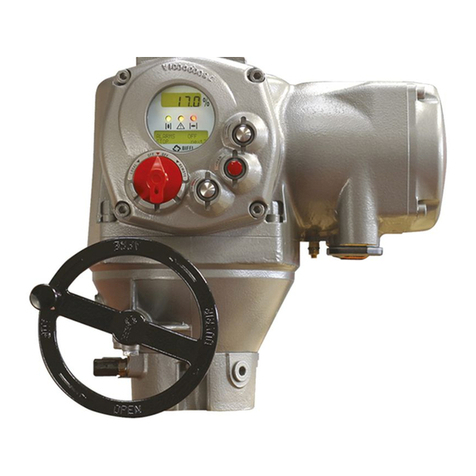
BIFFI F01-2000 Parts list manual
BIFFI
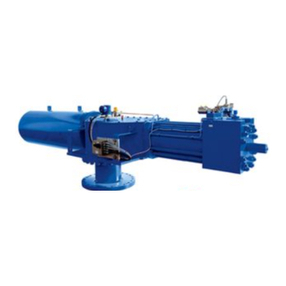
BIFFI OLGAS-H User manual
BIFFI
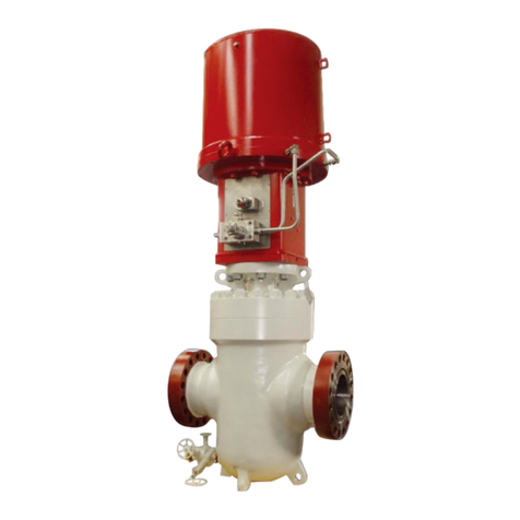
BIFFI HLAS-C Series User manual
BIFFI
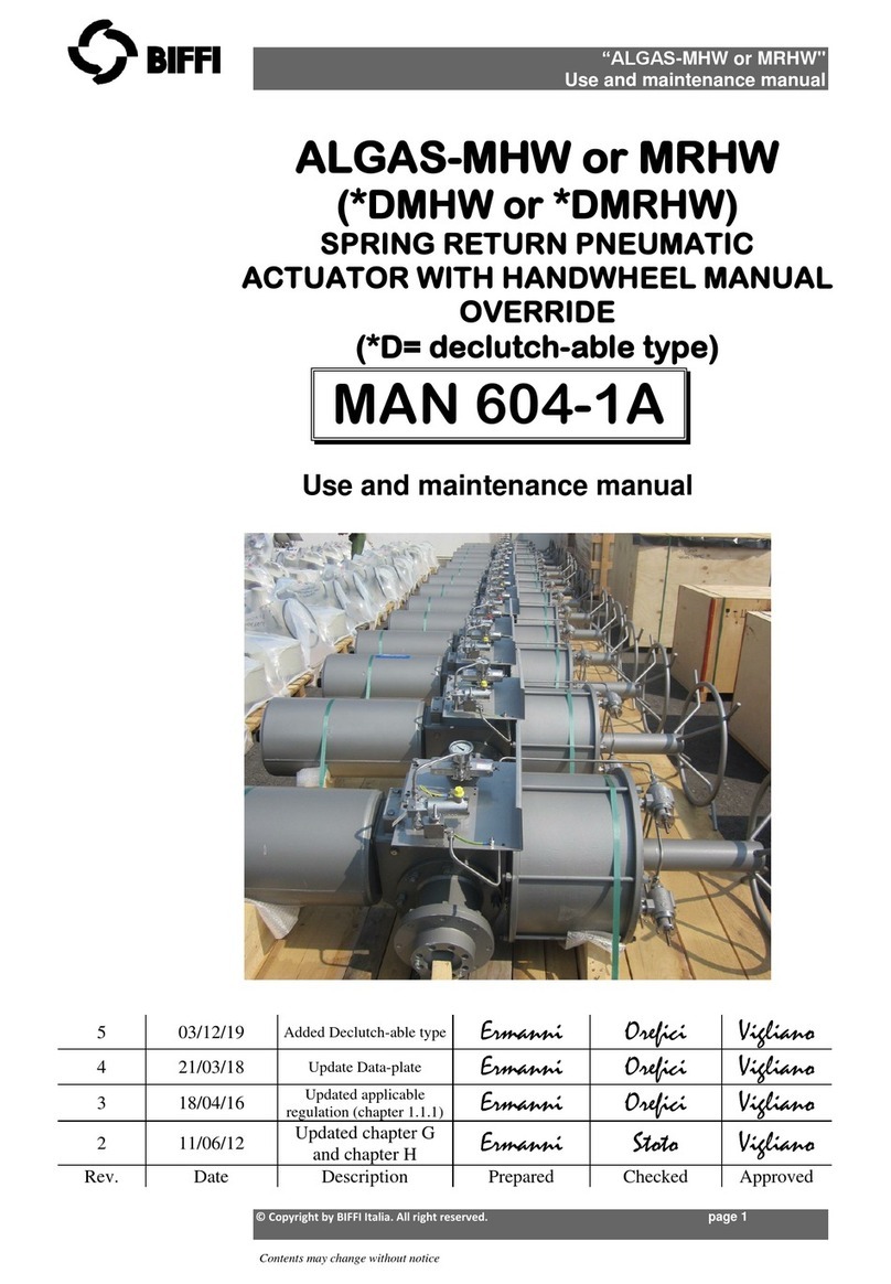
BIFFI ALGAS-MHW User manual
BIFFI
BIFFI ALGA Series User manual
Popular Controllers manuals by other brands
Mold-Masters
Mold-Masters TempMaster Series quick guide

Mitsubishi Electric
Mitsubishi Electric FX2N-10PG user manual

Curtis
Curtis 1232E manual
Rockwell Automation
Rockwell Automation Allen-Bradley MicroLogix 1400 Series user manual
Infineon
Infineon CoolSET-F3R ICE3BRXX65JZ series Design guide

Festo
Festo CECC-X-M1 series Brief description
