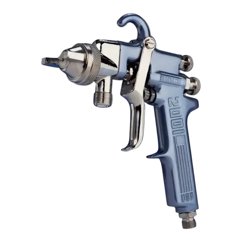
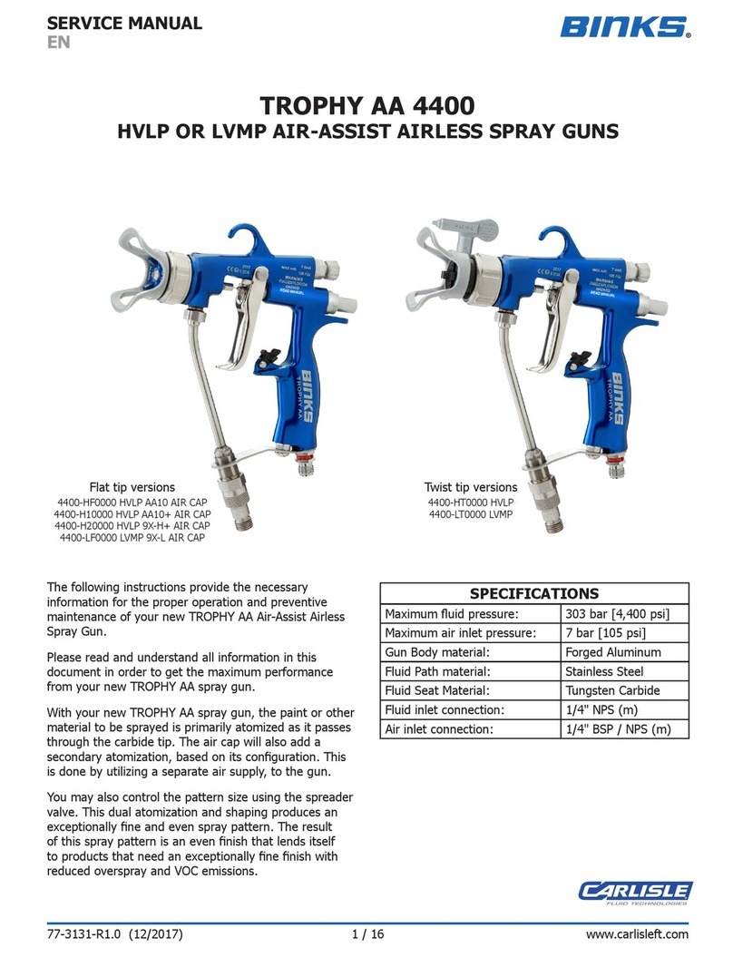
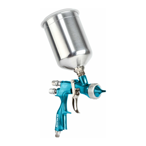
Binks TROPHY AA 4400 User manual

TROPHY AA 4400
HVLP OR LVMP AIR-ASSIST
AIRLESS SPRAY GUNS
Twist tip versions
4400-HT0000 HVLP
4400-LT0000 LVMP
Flat tip versions
4400-HF0000 HVLP AA10 AIR CAP
4400-H10000 HVLP AA10+ AIR CAP
4400-H20000 HVLP 9X-H+ AIR CAP
4400-LF0000 LVMP 9X-L AIR CAP
The following instructions provide the necessary
information for the proper operation and preventive
maintenance of your new TROPHY AA Air-Assist Airless
Spray Gun.
Please read and understand all information in this
document in order to get the maximum performance
from your new TROPHY AA spray gun.
With your new TROPHY AA spray gun, the paint or other
material to be sprayed is primarily atomized as it passes
through the carbide tip. The air cap will also add a
secondary atomization, based on its conguration. This
is done by utilizing a separate air supply, to the gun.
You may also control the pattern size using the spreader
valve. This dual atomization and shaping produces an
exceptionally ne and even spray pattern. The result
of this spray pattern is an even nish that lends itself
to products that need an exceptionally ne nish with
reduced overspray and VOC emissions.
SPECIFICATIONS
Maximum uid pressure: 303 bar [4,400 psi]
Maximum air inlet pressure: 7 bar [105 psi]
Gun Body material: Forged Aluminum
Fluid Path material: Stainless Steel
Fluid Seat Material: Tungsten Carbide
Fluid inlet connection: 1/4" NPS (m)
Air inlet connection: 1/4" BSP / NPS (m)
77-3131-R2 (3/2018) 1 / 16 www.carlisleft.com
EN
SERVICE MANUAL

DJ Hasselschwert
Toledo, OH 43612
4-3193R-1
11-Jul-17
Signed for and on behalf of
Carlisle Fluid Technologies:
Machinery Directive 2006/42/EC
ATEX Directive 2014/34/EU
by complying with the following statutory documents and harmonized standards:
EN ISO 12100:2010 Safety of Machinery - General Principles for Design
BS EN 1953:2013 Atomising and spraying equipment for coating materials - Safety requirements
EN 13463-1:2009 Non electrical equipment for use in potentially explosive atmospheres - Basic methods and requirements
Providing all conditions of safe use / installation stated within the product manuals have been complied with and also installed
in accordance with any applicable local codes of practice.
(Vice President: Global
Product Development)
The object of the declaration described above is in conformity with the relevant Union harmonisation
legislation:
This Declaration of Conformity
/incorporation is issued under the sole
responsiblility of the manufacturer:
Carlisle Fluid Technologies Inc.,
320 Phillips Ave.,
Toledo, OH 43612
EU Declaration of Conformity
II 2 G X
Notified body details and role:
Element Materials Technology. WN8 9PN UK
Lodging of Technical file
Protection Level:
Product Description/Object of Declaration:
Solvent and Water based Materials
Zone 1
Suitable for use in hazardous area:
This Product is designed for use with:
AIR-ASSIST
AIRLESS SPRAY GUN
EN
77-3131-R2 (3/2018)2 / 16www.carlisleft.com

Binks reserves the right to modify equipment specification without prior notice.
LOCK OUT / TAG-OUT
Failure to de-energize, disconnect, lock out and tag-out all power
sources before performing equipment maintenance could cause
serious injury or death.
OPERATOR TRAINING
All personnel must be trained before operating finishing
equipment.
EQUIPMENT MISUSE HAZARD
Equipment misuse can cause the equipment to rupture,
malfunction, or start unexpectedly and result in serious injury.
PROJECTILE HAZARD
You may be injured by venting liquids or gases that are released
under pressure, or flying debris.
PINCH POINT HAZARD
Moving parts can crush and cut. Pinch points are basically any
areas where there are moving parts.
INSPECT THE EQUIPMENT DAILY
Inspect the equipment for worn or broken parts on a daily basis.
Do not operate the equipment if you are uncertain about its
condition.
In this part sheet, the words WARNING, CAUTION and NOTE are used to
emphasize important safety information as follows:
Hazards or unsafe practices which
could result in minor personal injury,
product or property damage.
!
CAUTION
Hazards or unsafe practices which
could result in severe personal
injury, death or substantial property
damage.
!
WARNING
Important installation, operation or
maintenance information.
NOTE
Read the following warnings before using this equipment.
READ THE MANUAL
Before operating finishing equipment, read and understand all
safety, operation and maintenance information provided in the
operation manual.
WEAR SAFETY GLASSES
Failure to wear safety glasses with side shields could result in
serious eye injury or blindness.
NEVER MODIFY THE EQUIPMENT
Do not modify the equipment unless the manufacturer provides
written approval.
IT IS THE RESPONSIBILITY OF THE EMPLOYER TO PROVIDE THIS INFORMATION TO THE OPERATOR OF THE EQUIPMENT.
FOR FURTHER SAFETY INFORMATION REGARDING THIS EQUIPMENT, SEE THE GENERAL EQUIPMENT SAFETY BOOKLET (77-5300).
KNOW WHERE AND HOW TO SHUT OFF THE EQUIPMENT
IN CASE OF AN EMERGENCY
PRESSURE RELIEF PROCEDURE
Always follow the pressure relief procedure in the equipment
instruction manual.
NOISE HAZARD
You may be injured by loud noise. Hearing protection may be
required when using this equipment.
STATIC CHARGE
Fluid may develop a static charge that must be dissipated through
proper grounding of the equipment, objects to be sprayed and all
other electrically conductive objects in the dispensing area. Improper
grounding or sparks can cause a hazardous condition and result in
fire, explosion or electric shock and other serious injury.
PROP 65 WARNING
WARNING: This product contains chemicals known to the
State of California to cause cancer and birth defects or other
reproductive harm.
WEAR RESPIRATOR
Toxic fumes can cause serious injury or death if inhaled.
Wear a respirator as recommended by the fluid and solvent
manufacturer’s Safety Data Sheet.
TOXIC FLUID & FUMES
Hazardous fluid or toxic fumes can cause serious injury or death if
splashed in the eyes or on the skin, inhaled, injected or
swallowed. LEARN and KNOW the specific hazards or the fluids
you are using.
KEEP EQUIPMENT GUARDS IN PLACE
Do not operate the equipment if the safety devices have been
removed.
!
WARNING
AUTOMATIC EQUIPMENT
Automatic equipment may start suddenly without warning.
FIRE AND EXPLOSION HAZARD
Improper equipment grounding, poor ventilation, open flame or
sparks can cause a hazardous condition and result in fire or
explosion and serious injury.
MEDICAL ALERT
Any injury caused by high pressure liquid can be serious. If you
are injured or even suspect an injury:
• Go to an emergency room immediately.
• Tell the doctor you suspect an injection injury.
• Show the doctor this medical information or the medical alert
card provided with your airless spray equipment.
• Tell the doctor what kind of fluid you were spraying or
dispensing.
GET IMMEDIATE MEDICAL ATTENTION
To prevent contact with the fluid, please note the following:
• Never point the gun/valve at anyone or any part of the body.
• Never put hand or fingers over the spray tip.
• Never attempt to stop or deflect fluid leaks with your hand,
body, glove or rag.
• Always have the tip guard on the spray gun before spraying.
• Always ensure that the gun trigger safety operates before
spraying.
EN
77-3131-R2 (3/2018) 3 / 16 www.carlisleft.com
INSTALLATION
Before proceeding, make sure trigger lock is engaged.
NOTE
1. Connect your high-pressure uid hose to the gun uid
inlet and tighten securely.
2. Connect your air hose to the gun air connection and
tighten securely.
3. Slowly increase air to the pump to obtain a uid pressure
at the gun’s lower end of the pressure range. A typical
starting uid pressure is 70 bar [1000 psi]. Actual starting
pressure points may be higher or lower and be dependent
on the type of pump used, the type of material sprayed,
and the spray gun itself.
4. Using the control knob of the gun air regulator at the air
control, set the gun shaping air pressure at 0 bar [0 psi].
5. To test the spraying pattern, spray a sample piece of wood
or cardboard with a fast pass about 30cm [1 ft] away
from the surface. The results of the test will allow you to
determine the uniformity of the particle size and spraying
pattern.
6. If the spraying pattern develops tails or is not uniform,
gradually increase the air pressure as necessary to
develop a uniform spraying pattern. 1 bar [14 psi] is the
maximum inlet air pressure for HVLP air caps, or use 1.4-
2.8 bar [20-40 psi] inlet air pressure for LVMP air caps.
7. If the pattern is still unacceptable, you may gradually
increase the uid pump air pressure in 0.7 bar [10 psi]
increments using the uid pump air regulator control
knob. Repeat step 6, as needed.
8. Once the quality of spray is acceptable, begin spraying.
If the spraying rate is too slow to keep up with the
production line speed, or if the quantity of material
sprayed is inadequate for acceptable coverage, repeat
step 7, until desired pattern and material quantity is
achieved. If the maximum uid pressure is reached before
the required material coverage and spraying speed are
achieved, you may need to switch to a different uid tip.
FLUID TIP SELECTION
Factors to consider in selecting a uid tip for an air-assist
airless spray gun include:
• The size of the parts being sprayed.
• The production line speed
• The material ow rate and lm thickness.
• The viscosity of the material applied
• The type of material applied.
• The quality of atomization of the coating required.
The selection of a uid tip necessary to perform a specic
spraying job is best determined through a combination of
experimentation and expert advice from your material and
equipment suppliers.
Air Supply
Oil & Water
Extractor MX Pump
Fluid
Filter
Air
Control
Trophy AA
Spray Gun
SPRAY PATTERN ADJUSTMENT
• Turn the spreader valve knob indicated below
counterclockwise to decrease the pattern size;
clockwise to increase pattern size.
Spray pattern adjustment
control knob
For HVLP spray, spray pattern adjustment feature requires
1 bar [14 psi] maximum of air inlet pressure.
For LVMP spray, spray pattern adjustment requires
approximately 1.4-2.8 bar [20-40 psi] of air inlet pressure.
Higher fluid pressures will require a higher air inlet pressure
to accommodate pattern adjustment.
NOTE
FLUID HOSES
Air-assist airless spray guns operate at uid pressures higher
than operating pressures of air spray guns. As a result, when
operating an air-assist airless spray gun, it is critical to select
the appropriate uid hose that is rated for the pressure range
at which the airless gun is operated.
The spray gun must be earthed to dissipate any electrostatic charges which may be created by fluid or air flows.
This can be achieved through the spray gun mounting, or conductive air/fluid hoses. Electrical bond from the spray gun to earth
should be checked and a resistance of less than 106Ohms is required.
!
WARNING
EN
77-3131-R2 (3/2018)4 / 16www.carlisleft.com

GENERAL TROUBLESHOOTING
PROBLEM CAUSE REMEDY
Fluid leaking from needle
packing
Worn needle packing or needle shaft Replace air valve & uid needle assembly, item 5.
Loose needle packing Tighten packing nut gradually until leak stops.
Fluid leaking from the front of
the gun
Worn or damaged needle ball Replace air valve & uid needle assembly, item 5.
Worn seat assembly Replace uid nozzle, item 9.
Fluid in air passages Spray tip seal leaking Tighten air cap & nozzle guard assembly, item 11 or 13.
Replace carbide tip seal. RS-5000-K5 or RS-5000-K10
Leaking around uid seat Tighten or replace uid nozzle, item 9.
Fluid slow to shut off Fluid buildup on needle assembly Clean or replace air valve & uid needle assembly, item 5.
No uid output when gun is
triggered
Tip orice is plugged Flat tips - Turn off uid supply. Relieve pressure into a closed
earth-grounded container. Engage trigger safety. Remove air
cap/nozzle guard assembly and spray tip. Clean or replace
the spray tip, item 12.
Twist tips – Rotate twist tip 180° within the air cap, then
spray into a closed earth-grounded container to try to clear
tip of any debris. If that fails, turn off uid supply. Engage
trigger safety. Remove air cap/nozzle guard assembly and
spray tip. Clean or replace the twist tip, item 10.
Needle is damaged or broken Turn off uid supply. Relieve pressure into a closed earth-
grounded container. Engage trigger safety. Replace air valve
& uid needle assembly, item 5.
Fluid lter is plugged Turn off uid supply. Relieve pressure into a closed-grounded
container. Engage trigger safety. Turn off air supply to pump
and relieve uid pressure from pump using bypass valve on
pump. Very slowly loosen the uid hose connection at the
gun to relieve any pressure in the hose. Remove the uid
hose. Using two wrenches, one to hold the uid tube in
place, and the other to remove the nut. Open the uid lter,
and clean or replace the lter element, item 17e.
Fluid hose is plugged Turn off uid supply. Relieve pressure into a closed-grounded
container. Engage trigger safety. Turn off air supply to pump
and relieve uid pressure from pump using bypass valve on
pump. Very slowly loosen the uid hose connection at the
gun to relieve any pressure in the hose. Remove the hose
and clear obstruction, or replace hose.
Needle Packing Nut
Trigger Safety
Fluid Filter
EN
77-3131-R2 (3/2018) 5 / 16 www.carlisleft.com
This manual suits for next models
12
Table of contents
Other Binks Paint Sprayer manuals

Binks
Binks MAG HVLP 4006-1100-0 User manual

Binks
Binks HP 4/32 User manual

Binks
Binks 102-2400 FRP User manual

Binks
Binks 7N User manual

Binks
Binks MACH 2A User manual

Binks
Binks 44-6000 Troubleshooting guide

Binks
Binks Mag II User manual

Binks
Binks HP 6/60 User manual

Binks
Binks TROPHY SERIES User manual

Binks
Binks Signature Series User manual

Binks
Binks 460 User manual

Binks
Binks AA4000 User manual

Binks
Binks M1-G HVLP User manual

Binks
Binks AA1600M User manual

Binks
Binks 2100 gw User manual

Binks
Binks TROPHY 2466 SERIES User manual

Binks
Binks 202-755 User manual

Binks
Binks SB-E-A1-21-1 User manual

Binks
Binks EMG Series User manual

Binks
Binks M1-G HVLP User manual