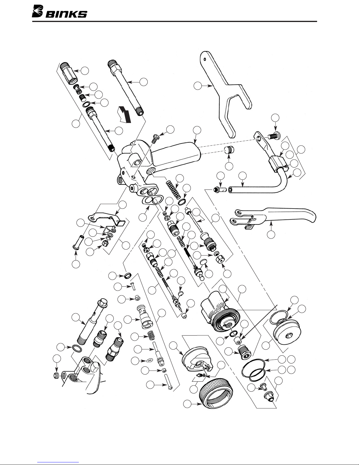
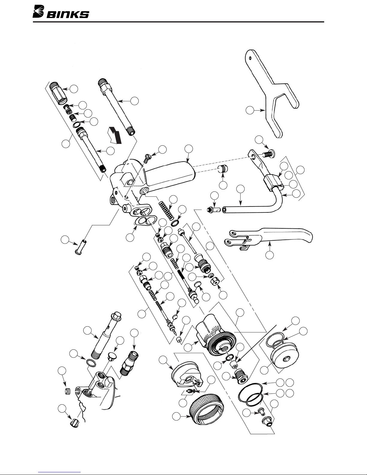
Binks 102-2400 FRP User manual

Binks MODELS 102-2400 FRP,
102-2500 GEL-COAT, AND
102-2545 VINYL ESTER
AIR-ASSISTED AIRLESS
CENTURY SPRAY GUNS
Replaces
Part Sheet
77-2520R-7
Part
Sheet
77-2520R-8
Be sure you understand ALL of the following instructions
thoroughly BEFORE operating any part of the airless equip-
ment system. CONSULT YOUR BINKS REPRESENTA-
TIVE TO CLEAR UP ANY ITEMS OF INSTRUCTION
YOU DO NOT UNDERSTAND.
1. Under no circumstances should the spray gun be carelessly
handled nor its spray (even when the nozzle is removed)
directed at close proximity at any part of the human body.
2. NEVER clean, change, or remove nozzle from the spray
gun without doing the following:
a. Lock trigger (62) by pushing forward. Rotate locking
block (68) in upward position.
b. Shut off pump and turn off air supply.
c. Release fluid pressure in the entire system, from pump
to spray gun. Stop pump in down position.
3. NEVER attempt to force the flow of liquid backward
through the gun.
4. NEVER plug a hose leak with your finger, with adhesive
tape, or other “stop-gap” device.
5. NEVER operate the airless system with a defective hose.
ALWAYS replace the defective hose immediately. For
continuing safety, users are urged to:
a. ALWAYS handle carefully all hose connections, joints,
and seating surfaces on the spray gun to prevent dam-
age.
b. NEVER kink or bend the fluid hose into less than a
four inch radius.
c. FREQUENTLY check the hose for kinks or abrasions.
These may develop into a rupture.
d. NEVER use standard hardware to modify the airless
system. ALWAYS use Binks high pressure fittings
only.
6. The airless pump must be grounded before operating the
airless system.
WARNING — HIGH PRESSURE — WARNING
UP TO 2500 POUNDS PER SQUARE INCH
•DO NOT POINT SPRAY GUN AT ANY PART OF THE HUMAN BODY
•FLUID UNDER HIGH PRESSURE CAN PENETRATE THE SKIN AND CAUSE SEVERE INTERNAL INJURY
•IN CASE OF INJURY OBTAIN MEDICAL ATTENTION IMMEDIATELY
•BE SURE TO REPORT NATURE OF INJURY AND TYPE OF FLUID OR SOLVENT TO THE DOCTOR
AIR ASSIST
AIR CAP
CATALYST
INJECTOR
CATALYST FILTER
CENTURY TIP
TRIGGER LOCK
AIR ASSIST INLET
1/4 NPS(m) / 1/4 NPT(m)
CATALYST INLET
1/4 NPS(m)
RESIN INLET
1/4 NPS(m)
102-2400 Century Wet-Out Gun
111-4052 Wrench
102-2521 Catalyst Injector
102-2526 Catalyst Injector
102-2531 Catalyst Injector
106-1170 Kit
102-2500 Century Gel-Coat Gun
111-4052 Wrench
102-2515 Catalyst Injector
102-2518 Catalyst Injector
102-2521 Catalyst Injector
106-1170 Kit
102-2545 Century Vinyl Ester Gun
111-4052 Wrench
102-2521 Catalyst Injector
102-2526 Catalyst Injector
106-1170 Kit
CHOPPER INLET
(not shown—see page 4)

2
WARNING
!
In this part sheet, the words WARNING, CAUTION and NOTE are used to emphasize important safety information as follows:
CAUTION
Hazards or unsafe practices which could
result in minor personal injury, product
or property damage.
!
WARNING
Hazards or unsafe practices which could
result in severe personal injury, death
or substantial property damage.
!
NOTE
Important installation, operation or
maintenance information.
Read the following warnings before using this equipment.
FOR FURTHER SAFETY INFORMATION REGARDING BINKS AND DEVILBISS EQUIPMENT,
SEE THE GENERAL EQUIPMENT SAFETY BOOKLET (77-5300).
READ THE MANUAL
Before operating finishing equipment, read and
understand all safety, operation and maintenance
information provided in the operation manual.
PLURAL COMPONENT MATERIALS HAZARD
Because of the vast number of chemicals that could
be used and their varying chemical reactions, the
buyer and user of this equipment must determine
all facts relating to the materials used, including
any of the potential hazards involved.
NOISE HAZARD
You may be injured by loud noise. Hearing protection
may be required when using this equipment.
FIRE AND EXPLOSION HAZARD
Improper equipment grounding, poor ventilation,
open flame or sparks can cause hazardous
conditions and result in fire or explosion and
serious injury.
PINCH POINT HAZARD
Moving parts can crush and cut. Pinch points are
basically any areas where there are moving parts.
KNOW WHERE AND HOW TO SHUT OFF THE
EQUIPMENT IN CASE OF AN EMERGENCY
PRESSURE RELIEF PROCEDURE
Always follow the pressure relief procedure in the
equipment instruction manual.
WEAR SAFETY GLASSES
Failure to wear safety glasses with side shields
could result in serious eye injury or blindness.
DE-ENERGIZE, DEPRESSURIZE, DISCONNECT
AND LOCK OUT ALL POWER SOURCES DURING
MAINTENANCE
Failure to De-energize, disconnect and lock out
all power supplies before performing equipment
maintenance could cause serious injury or death.
OPERATOR TRAINING
All personnel must be trained before operating
finishing equipment.
EQUIPMENT MISUSE HAZARD
Equipment misuse can cause the equipment to
rupture, malfunction, or start unexpectedly and
result in serious injury.
KEEP EQUIPMENT GUARDS IN PLACE
Do not operate the equipment if the safety
devices have been removed.
HIGH PRESSURE CONSIDERATION
High pressure can cause serious injury. Relieve all
pressure before servicing. Spray from the spray
gun, hose leaks, or ruptured components can
inject fluid into your body and cause extremely
serious injury.

3
Do not handle or use until safety precautions
concerning Methyl Ethyl Ketone Peroxides in
the Manufacturer’s literature have been read
and understood.
Contact with foreign materials, especially
strong mineral acids, metals (including certain
equipment and containers) or metal salts, or
exposure to heat above 135° F (57° C) may
lead to violent decomposition, releasing
flammable vapors which may self-ignite.
Do not get into eyes or on skin or clothing.
Wear eye and skin protection when handling.
Avoid breathing mist. Use with adequate
ventilation. Store only it in the original
closed container. Wash hands thoroughly
after handling. Protect from direct sunlight,
heat, sparks and other sources of ignition.
Prevent contamination with foreign materials.
Do not add to hot materials.
To maintain the chemical activity store below
100° F (38° C).
In case of fire, use water spray, foam or dry
chemical.
In case of spill or leak, absorb or blend with
inert, non-combustible material. Put in suitable
container. Dispose of immediately in
accordance with federal, state and local
regulations.
Do not reuse container as some of the original
hazardous contents may still be present.
Follow the above precautions in handling.
HALOGENATED HYDROCARBON
SOLVENTS CAN CAUSE AN EXPLOSION
WHEN IN CONTACT WITH ALUMINUM
COMPONENTS OF A PRESSURIZED OR
CLOSED FLUID SYSTEM (PUMPS,
HEATERS, FILTERS, etc.)
The same possibility of an explosion is possible
with the galvanized coatings in pressure tanks.
The possibility of a non-flammable explosion
increases greatly at high operating temperatures.
The explosion could be of sufficient strength to
cause bodily injury, death, and substantial
property damage.
Cleaning agents, coatings, or adhesives may
contain HALOGENATED HYDROCARBON
SOLVENTS. CHECK WITH YOUR SOL-
VENT AND PAINT SUPPLIER.
If you are now using a Halogenated Hydrocarbon
Solvent in a pressurized fluid system with
aluminum components or galvanized wetted
parts, the following steps should be taken
immediately:
1. Remove all pressure; drain and disconnect
the entire system.
2. Inspect and replace all corroded parts.
3. Contact your solvent supplier for a
NON-HALOGENATED SOLVENT to
flush and clean the system of all residues.
HALOGENATED Solvents are defined as any
hydrocarbon solvent containing any of the
following elements:
CHLORINE “CHLORO” (Cl)
BROMINE “BROMO” (Br)
FLUORINE “FLUORO” (F)
IODINE “IODO” (I)
Of those listed, the Chlorinated Solvents will
most likely be the type used as a cleaning agent
or solvent in an adhesive or coating. The most
common are:
METHYLENE CHLORIDE
1,1,1, TRICHLORETHANE
PERCHLORETHYLENE
Although stabilizers have been added to some
of the solvents to reduce their corrosive effect,
we are aware of none that will prevent these
solvents from reacting under all conditions
with aluminum components or galvanized
coatings.
Previous use of the solvents under pressurized
conditions, without incident, does not necessarily
indicate that it can be considered safe.
These guns are constructed with
components of aluminum alloy
and SHOULD NOT be used with any
Halogenated Hydrocarbon solvents.
WARNING
!
WARNING
!
When using Binks equipment with
Methyl Ethyl Ketone Peroxide in Plasticizer
OBSERVE the following precautions
CORROSIVE TO THE EYES – MAY CAUSE BLINDNESS.
MAY BE FATAL IF SWALLOWED. STRONG IRRITANT.
CONTAMINATION OR HEAT MAY LEAD TO FIRE OR
EXPLOSIVE DECOMPOSITION. COMBUSTIBLE.
READ & UNDERSTAND THE MATERIAL SAFETY DATA SHEET FROM
MATERIAL SUPPLIER
FIRST AID
EYES
Wash immediately (seconds count) with
water and continue washing for at least
15 minutes. Obtain medical attention.
SKIN
Wash with soap and water. Remove
contaminated clothes and shoes and again
wash thoroughly with soap and water.
SWALLOWING
Administer large quantities of milk or
water. Obtain immediate medical attention
for lavage.

4
102-2400 CENTURY GUN (FRP)
1
6
7
7a
8
9
10
67
80
81
73 74
72
8a
2
26
19 17
16
23
14
20
21
18
11
13
12 14
15
16
17
35
34
36 37
33
38
39
40
55
61
48
43
41 85
66
64
65
64
24 25 89 68
62
63
54
60
59 58 57
56
28 17
29 88
84
49 50
87 86
31
32
3
4
5
51
52
53
44
45
46
47
42
VIEW A
VIEW A
Note: Items 24 and 68 not available separately.
Resin Seat (10) not part
of head Assembly (9).

5
ITEM PART
NO. NO. DESCRIPTION QTY.
1102-2434 AIR/CATALYST CAP
RETAINER RING .............................. 1
2102-2431 AIR/CATALYST CAP .......................... 1
3— CATALYST INJECTOR
(See Injector Chart) ............................ 1
4102-2433*•◗O-RING .............................................. 1
5— TIP ASSEMBLY
(See Tip Assembly Chart) .................... REF
6102-2499* TIP SEAL
(See Note under Tip Assembly Chart) .. REF
720-4542*• ◗O-RING (Silicone Red) ......................... 1
7A 20-6473◗EPR O-RING (Optional)....................... —
820-6296*• ◗O-RING (Silicone Red) ......................... 1
8A 20-6474◗EPR O-RING (Optional)....................... —
9102-2401 HEAD ASSEMBLY.............................. 1
10 102-2447•RESIN SEAT ....................................... 1
11 102-2410•RESIN NEEDLE ASSEMBLY................ 1
12 102-2412 NEEDLE SUB-ASSEMBLY................... 1
13 102-2411*•◗PACKING ........................................... 1
14 102-2613 SPRING .............................................. 2
15 102-2419 RESIN PACKING NUT ........................ 1
16 102-2428 CONVEX NUT.................................... 2
17 52-487 BRASS NUT........................................ 3
18 102-2448•CATALYST SEAT ............................... 1
19 102-2420•CATALYST NEEDLE ASSEMBLY........ 1
20 102-2422 NEEDLE SUB-ASSEMBLY................... 1
21 102-2421*•◗PACKING ........................................... 1
23 102-2429 CATALYST PACKING NUT ................ 1
24 — GUARD TUBE (Reference Only) .......... —
25 20-5006 C-CLIP ................................................ 2
26 102-2621 CHOPPER VALVE ASSEMBLY ........... 1
28 20-6631 SCREW............................................... 1
29 20-6663O-RING .............................................. 1
31 102-3335*SEAL .................................................. 1
32 102-2649SPRING .............................................. 1
33 102-2615 AIR ASSIST VALVE ASSEMBLY ......... 1
34 54-2417 NUT ................................................... 1
35 54-2419*PACKING ........................................... 1
36 54-751 BODY................................................. 1
37 54-744*VALVE ASSEMBLY ............................ 1
38 54-749*AIR ASSIST VALVE SEAL ................... 1
39 54-1964*SPRING .............................................. 1
40 102-2427*GASKET ............................................. 1
ITEM PART
NO. NO. DESCRIPTION QTY.
41 102-2402 HANDLE........................................... 1
42 102-2440 CATALYST INLET/FILTER ASS’Y. ..... 1
43 102-2442 TUBE ASSEMBLY ............................. 1
44 20-4858*□O-RING ............................................ 1
45 102-2181*•□FILTER SCREEN ................................ 1
46 54-1263 FILTER SUPPORT.............................. 1
47 102-2441 MATERIAL INLET Catalyst ................ 1
48 102-2435 RESIN INLET..................................... 1
49 20-3111 PIPE PLUG 1/8" NPT.......................... 1
50 102-2408•GASKET 1/2 I.D. x 9/16 O.D................ 1
51 102-2409 HEAD RETAINER ............................. 1
52 102-2467 CHOPPER AIR INLET........................ 1
53 102-2403 AIR ASSIST INLET ............................ 1
54 102-2470 CHOPPER TRIGGER ASSEMBLY ...... 1
55 102-2471 CHOPPER TRIGGER ......................... 1
56 102-2472 ON/OFF SELECTOR .......................... 1
57 102-2474 LOW FRICTION WASHER ................ 1
58 102-2475 WAVE SPRING ................................. 1
59 102-2473 RETAINER SCREW ........................... 1
60 54-1020 TRIGGER STUD ................................ 1
61 82-126 TRIGGER SCREW ............................. 1
62 102-2489 TRIGGER .......................................... 1
63 102-2404 GUARD STUD .................................. 1
64 102-2405 GUARD ASSEMBLY ......................... 1
65 20-6295 SCREW 5/16"-24 x 5/8" B.H. ............... 1
66 54-714 AIR PLUG ......................................... 1
67 102-2494 NIGHT CAP ASSEMBLY ................... 1
68 — LOCKING BLOCK (Reference Only) ... —
69 102-2438•5/64" DOWEL PIN (Not Shown)........ 1
70 102-2439•13/64" DOWEL PIN (Not Shown)...... 1
71 102-2510•3/8" DOWEL PIN (Not Shown).......... 1
72 102-2506 HEAD INSERT .................................. 1
73 102-2505 SEAL................................................. 1
74 102-2504 HEAD MACHINING ......................... 1
79 102-2511•1/4" DOWEL PIN (Not Shown).......... 1
80 20-5052 O-RING ............................................ 1
81 20-6183 O-RING ............................................ 1
84 102-2651 AIR VALVE BODY............................ 1
85 111-4052 WRENCH.......................................... 1
86 20-6502 SCREW ............................................. 1
87 102-2464VALVE.............................................. 1
88 102-2652 STEM................................................ 1
89 237-752 PLUNGER (Not Shown)...................... 1
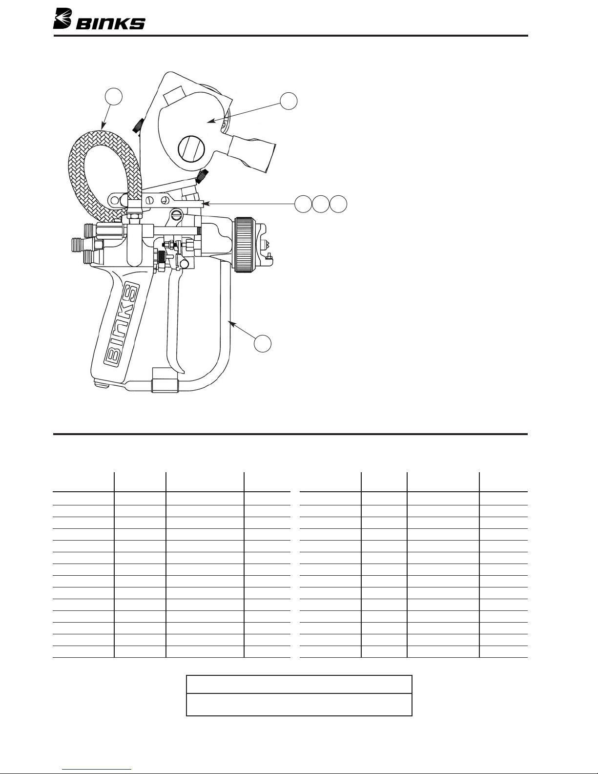
PARTS LIST
(When ordering, please specify Part No.)
ACCESSORIES
102-2478 3/8" NPS Resin Inlet
102-2446 Resin Seat, Carbide
ORDER SEPARATELY TOOLS LIST
1. 102-2432 DUAL CATALYST 3/16" IGNITION WRENCH
NOZZLE AIR CAP ASSEMBLY 5/16" IGNITION WRENCH
2. 102-285 CALIBRATION 3/8" WRENCH
NOZZLE ASSEMBLY 7/16" WRENCH
3. 102-2525 HV AIR CAP 9/16" WRENCH
3/16" ALLEN WRENCH
2 FLAT SCREWDRIVERS
5/64" DOWEL PIN
13/64" DOWEL PIN
•In 106-1171 Fluid Repair Kit. In 106-1172 Air Valve Repair Kit.
In 106-1173 O-Ring Kit (15 of Each). In 106-1174 Soft Seat Kit.
□In 106-1175 Catalyst Filter Repair Kit. ◗In 106-1170 Soft Seal Kit.
NOTE: Parts marked with * are only available from Binks in quantity packs
or Repair Kits. Refer to the Repair Kits for order numbers. See Price
List for minimum quantities.

6
1
6
7
7a
8
9
10
67
81
82
73
74
72
8a
2
19 17
16
23
22
20
21
18
11
13
12
14
15
16
17
35
34
36
37
33
38
39
40
61
48
43
78
83
66
64
65
64
24 25 86 68
62
63
80
3
4
5
44
45
46
47
42
VIEW
A
Note: Items 24 and 68 not available separately.
Note: A Carbide Seat (102-2446) is standard on
Model 102-2500 for Item 10.
Resin Seat (10) not part
of head Assembly (9).
102-2500 GEL-COAT CENTURY GUN
75 49
50
75
53
51
VIEW A

7
Binks Model 102-2500 GEL-COAT CENTURY GUN
ITEM PART
NO. NO. DESCRIPTION QTY.
1102-2434 AIR/CATALYST CAP
RETAINER RING ............................ 1
2102-2431 AIR/CATALYST CAP ........................ 1
3— CATALYST INJECTOR
(See Injector Chart) ...................... 1
4102-2433*•◗O-RING ............................................ 1
5—* TIP ASSEMBLY
(See Tip Assembly Chart) .................. REF
6102-2499* TIP SEAL
(See Note under Tip Ass’y. Chart) ...... REF
720-4542*• ◗O-RING ........................................... 1
7A 20-6473 ◗EPR O-RING (Size 2-022, Optional) .... —
820-6296*• ◗O-RING ........................................... 1
8A 20-6474 ◗EPR O-RING (Size 2-029, Optional) .... —
9102-2401 HEAD ASSEMBLY............................ 1
10 102-2446 RESIN SEAT Carbide .........................
11 102-2410•RESIN NEEDLE ASSEMBLY.............. 1
12 102-2412 NEEDLE SUB-ASSEMBLY................. 1
13 102-2411*•◗PACKING ......................................... 1
14 102-2613 SPRING ............................................ 1
15 102-2419 RESIN PACKING NUT ...................... 1
16 102-2428 CONVEX NUT .................................. 2
17 52-487 BRASS NUT...................................... 2
18 102-2448•CATALYST SEAT Nylon .................... 1
19 102-2420•CATALYST NEEDLE ASSEMBLY ...... 1
20 102-2422 NEEDLE............................................ 1
21 102-2421*•◗PACKING ......................................... 1
22 102-2616 SPRING ............................................ 1
23 102-2429 CATALYST PACKING NUT .............. 1
24 — GUARD TUBE (Reference Only) ........ —
25 20-5006 C-CLIP .............................................. 2
33 102-2615 AIR ASSIST VALVE ASSEMBLY ....... 1
34 54-2417 NUT ................................................. 1
35 54-2419*PACKING ......................................... 1
36 54-751 BODY............................................... 1
37 54-744*VALVE ASSEMBLY .......................... 1
ITEM PART
NO. NO. DESCRIPTION QTY.
38 54-749*AIR ASSIST VALVE SEAL ................ 1
39 54-1964*SPRING............................................ 1
40 102-2427*GASKET........................................... 1
42 102-2440 CATALYST INLET/FILTER ASS’Y...... 1
43 102-2442 TUBE ASSEMBLY ............................ 1
44 20-4858*•□O-RING............................................ 1
45 102-2181*•□FILTER SCREEN ............................... 1
46 54-1263 FILTER SUPPORT............................. 1
47 102-2441 MATERIAL INLET Catalyst ............... 1
48 102-2435 RESIN INLET ASSEMBLY................. 1
49 20-3111 PIPE PLUG....................................... 1
50 102-2408•GASKET 1/2 I.D. x .615 O.D. .............. 1
51 102-2409 HEAD RETAINER ............................ 1
53 102-2403 AIR ASSIST INLET............................ 1
61 82-126 TRIGGER SCREW ............................ 1
62 102-2489 TRIGGER ......................................... 1
63 102-2404 GUARD STUD ................................. 1
64 102-2405 GUARD ASSEMBLY ........................ 1
65 20-6295 SCREW 5/16"-24 x 5/8" B.H. .............. 1
66 54-714 AIR PLUG ........................................ 1
67 102-2494 NIGHT CAP ASSEMBLY .................. 1
68 — LOCKING BLOCK (Reference Only) .. —
69 102-2438•5/64" DOWEL PIN (Not Shown)....... 1
70 102-2439•13/64" DOWEL PIN (Not Shown)..... 1
71 102-2510•3/8" DOWEL PIN (Not Shown)......... 1
72 102-2506 HEAD INSERT ................................. 1
73 102-2505 SEAL................................................ 1
74 102-2504 HEAD MACHINING......................... 1
75 20-6753 HOLE PLUG Plastic .......................... 2
78 102-2402 HANDLE Gel-Coat ............................ 1
79 102-2511•1/4" DOWEL PIN (Not Shown)......... 1
80 102-2465 TRIGGER STUD ............................... 1
81 20-5052 O-RING............................................ 1
82 20-6183 O-RING............................................ 1
83 111-4052 WRENCH......................................... 1
86 237-752 PLUNGER (Not Shown)..................... 1
PARTS LIST
(When ordering, please specify Part No.)
ACCESSORIES
102-2478 3/8" NPS Resin Inlet Assembly.
102-2447 Soft Resin Seat.
TOOLS LIST
• 3/16" IGNITION WRENCH • 3/16" ALLEN WRENCH
• 5/16" IGNITION WRENCH • 2 FLAT SCREWDRIVERS
• 3/8" WRENCH • 5/64" DOWEL PIN
• 7/16" WRENCH • 13/64" DOWEL PIN
• 9/16" WRENCH
•In 106-1171 Fluid Repair Kit. In 106-1172 Air Valve Repair Kit.
In 106-1173 O-Ring Kit (15 of Each). In 106-1174 Soft Seat Kit.
□In 106-1175 Catalyst Filter Repair Kit. ◗In 106-1170 Soft Seal Kit.
NOTE: Parts marked with * are only available from Binks in Quantity
Packs or Repair Kits. Refer to the Repair Kits List for order
numbers. See Price List for minimum order quantities.

8
1
6
7
7a
8
9
10
67
81
82
73
74
72
8a
2
19 17
16
23
22
20
21
18
11
13
12
14
15
16
17
35
34
36
37
33
38
39
40
61
48
43
78
83
66
64
65
64
24 25 86 68
62
63
80
3
4
5
44
45
46
47
42
VIEW
A
Note: Items 24 and 68 not available separately.
Note: A Carbide Seat (102-2446) is standard on
Model 102-2545 for Item 10.
Resin Seat (10) not part
of head Assembly (9).
102-2545 VINYL ESTER CENTURY GUN
75 49
50
75
53
51
VIEW A

9
Binks Model 102-2545 VINYL ESTER CENTURY GUN
ITEM PART
NO. NO. DESCRIPTION QTY.
1102-2434 AIR/CATALYST CAP
RETAINER RING ............................ 1
2102-2431 AIR/CATALYST CAP ........................ 1
3— CATALYST INJECTOR
(See Injector Chart) ...................... 1
4102-2433*•◗O-RING ............................................ 1
5—* TIP ASSEMBLY
(See Tip Assembly Chart) .................. REF
6102-2499* TIP SEAL
(See Note under Tip Ass’y. Chart) ...... REF
720-4542*• ◗O-RING ........................................... 1
7A 20-6473 ◗EPR O-RING (Size 2-022, Optional) .... —
820-6296*• ◗O-RING ........................................... 1
8A 20-6474 ◗EPR O-RING (Size 2-029, Optional) .... —
9102-2401 HEAD ASSEMBLY............................ 1
10 102-2446 RESIN SEAT Carbide .........................
11 102-2410•RESIN NEEDLE ASSEMBLY.............. 1
12 102-2412 NEEDLE SUB-ASSEMBLY................. 1
13 102-2411*•◗PACKING ......................................... 1
14 102-2613 SPRING ............................................ 1
15 102-2419 RESIN PACKING NUT ...................... 1
16 102-2428 CONVEX NUT .................................. 2
17 52-487 BRASS NUT...................................... 2
18 102-2448•CATALYST SEAT Nylon .................... 1
19 102-2420•CATALYST NEEDLE ASSEMBLY ...... 1
20 102-2422 NEEDLE............................................ 1
21 102-2421*•◗PACKING ......................................... 1
22 102-2616 SPRING ............................................ 1
23 102-2429 CATALYST PACKING NUT .............. 1
24 — GUARD TUBE (Reference Only) ........ —
25 20-5006 C-CLIP .............................................. 2
33 102-2615 AIR ASSIST VALVE ASSEMBLY ....... 1
34 54-2417 NUT ................................................. 1
35 54-2419*PACKING ......................................... 1
36 54-751 BODY............................................... 1
37 54-744*VALVE ASSEMBLY .......................... 1
ITEM PART
NO. NO. DESCRIPTION QTY.
38 54-749*AIR ASSIST VALVE SEAL ................ 1
39 54-1964*SPRING............................................ 1
40 102-2427*GASKET........................................... 1
42 102-2440 CATALYST INLET/FILTER ASS’Y...... 1
43 102-2442 TUBE ASSEMBLY ............................ 1
44 20-4858*•□O-RING............................................ 1
45 102-2181*•□FILTER SCREEN ............................... 1
46 54-1263 FILTER SUPPORT............................. 1
47 102-2441 MATERIAL INLET Catalyst ............... 1
48 102-2478 RESIN INLET ASSEMBLY (3/8") ....... 1
49 20-3111 PIPE PLUG....................................... 1
50 102-2408•GASKET 1/2 I.D. x .615 O.D. .............. 1
51 102-2409 HEAD RETAINER ............................ 1
53 102-2403 AIR ASSIST INLET............................ 1
61 82-126 TRIGGER SCREW ............................ 1
62 102-2489 TRIGGER ......................................... 1
63 102-2404 GUARD STUD ................................. 1
64 102-2405 GUARD ASSEMBLY ........................ 1
65 20-6295 SCREW 5/16"-24 x 5/8" B.H. .............. 1
66 54-714 AIR PLUG ........................................ 1
67 102-2494 NIGHT CAP ASSEMBLY .................. 1
68 — LOCKING BLOCK (Reference Only) .. —
69 102-2438•5/64" DOWEL PIN (Not Shown)....... 1
70 102-2439•13/64" DOWEL PIN (Not Shown)..... 1
71 102-2510•3/8" DOWEL PIN (Not Shown)......... 1
72 102-2506 HEAD INSERT ................................. 1
73 102-2505 SEAL................................................ 1
74 102-2504 HEAD MACHINING......................... 1
75 20-6753 HOLE PLUG Plastic .......................... 2
78 102-2402 HANDLE Gel-Coat ............................ 1
79 102-2511•1/4" DOWEL PIN (Not Shown)......... 1
80 102-2465 TRIGGER STUD ............................... 1
81 20-5052 O-RING............................................ 1
82 20-6183 O-RING............................................ 1
83 111-4052 WRENCH......................................... 1
86 237-752 PLUNGER (Not Shown)..................... 1
PARTS LIST
(When ordering, please specify Part No.)
ACCESSORIES
102-2435 1/4" NPS Resin Inlet Assembly.
102-2447 Soft Resin Seat.
TOOLS LIST
• 3/16" IGNITION WRENCH • 3/16" ALLEN WRENCH
• 5/16" IGNITION WRENCH • 2 FLAT SCREWDRIVERS
• 3/8" WRENCH • 5/64" DOWEL PIN
• 7/16" WRENCH • 13/64" DOWEL PIN
• 9/16" WRENCH
•In 106-1171 Fluid Repair Kit. In 106-1172 Air Valve Repair Kit.
In 106-1173 O-Ring Kit (15 of Each). In 106-1174 Soft Seat Kit.
□In 106-1175 Catalyst Filter Repair Kit. ◗In 106-1170 Soft Seal Kit.
NOTE: Parts marked with * are only available from Binks in Quantity
Packs or Repair Kits. Refer to the Repair Kits List for order
numbers. See Price List for minimum order quantities.

10
5
1
MODEL 102-2455 CENTURY CHOPPER GUN ASSEMBLY
NEW TIP CHART FOR CENTURY SERIES GUNS
ASSEMBLY ORIFICE SPRAY WIDTH I.D.
PART NO. SIZE @ 12" NO.
108-91507 0.015 7" 1507
108-91807 0.018 7" 1807
108-91809 0.018 9" 1809
108-92107 0.021 7" 2107
108-92109 0.021 9" 2109
108-92111 0.021 11" 2111
108-92113 0.021 13" 2113
108-92307 0.023 7" 2307
108-92309 0.023 9" 2309
108-92607 0.026 7" 2607
108-92609 0.026 9" 2609
108-92612 0.026 12" 2612
108-93107 0.031 7" 3107
108-93109 0.031 9" 3109
ASSEMBLY ORIFICE SPRAY WIDTH I.D.
PART NO. SIZE @ 12" NO.
108-93605 0.036 5" 3605
108-93607 0.036 7" 3607
108-93609 0.036 9" 3609
108-94107 0.041 7" 4107
108-94109 0.041 9" 4109
108-94405 0.044 5" 4405
108-94407 0.044 7" 4407
108-94409 0.044 9" 4409
108-95107 0.051 7" 5107
108-95109 0.051 9" 5109
108-95707 0.057 7" 5707
108-96307 0.063 7" 6307
Refer to Part Sheet 77-2475 for Chopper Assembly.
NOTE
Additional tip seals available in 106-1177 Tip Seal Kit.
ITEM PART
NO. NO. DESCRIPTION QTY.
1102-2400 CENTURY GUN ASSEMBLY ............ 1
2102-2661 MOUNT BRACKET.......................... 1
320-1374 SCREW, FLAT HEAD SLOTTED ............. 1
420-6154 SCREW, FLAT HEAD SLOTTED ............. 1
5201-510 K-510 CHOPPER ASSEMBLY .......... 1
6237-573 CHOPPER AIR HOSE*..................... REF
*Included with the 201-510 Chopper Assembly
PARTS LIST
(When ordering, please specify Part No.)
234
6

11
Your new Binks Century Gun will give you excellent performance
as long as it is handled properly. Read over these sections before
operating the gun.
CATALYZATION
The catalyst orifice should be sized to minimize catalyst pres-
sure. Over-catalyzation can show up as a split pattern, misting
of the resin, streaking of the catalyst in the resin, or detection
of catalyst fumes. A wide range of catalyst injectors is avail-
able to accommodate your specific needs. Refer to the Catalyst
Injector Selection Chart for the various orifice sizes.
Catalyst fumes should be minimal. The Binks Century guns
utilize external advanced catalyzation technology, “EXACT”
which mixes all of the catalyst exiting the catalyst injector into
the resin stream.
FLUID/AIR PRESSURE OF THE RESIN/GEL-COAT
To reduce overspray and obtain maximum efficiency of the
Century gun, the fluid and air pressure should be reduced to
their lowest possible pressures that produce acceptable
atomization and finish.
Typically, for unfilled resins and unpigmented gel-coats, the fluid
pressure needed for proper atomization is approximately 200-700
psi. For filled resins and pigmented gel-coats, the fluid pressure
will be significantly higher, approximately 400-1500 psi.
Depending on your system, the fluid pressures you use will vary
higher or lower than these numbers, but they serve as a good
starting point.
Typically, the pressure setting at nozzle for the atomizing air
will be from 3 to 10 psi, although pressures up to 30 psi are
acceptable. The atomizing air is necessary for proper catalyza-
tion and therefore should not be reduced below 5 psi. Also,
depending upon the catalyst, it may be necessary to
increase/decrease the atomizing air in order to induce proper
catalyzation after determining the necessary air pressure for a
good spray pattern.
TIMING OF THE AIR, CATALYST AND
RESIN VALVES
The timing of the air, catalyst and resin valves is an important
factor in the operation of the Century gun.
The gun will appear to leak if the lag between engaging the
atomizing air and the fluid needles is unnecessarily long.
While releasing the trigger, the resin and catalyst shut off first
and the atomizing air has not shut off yet. The atomizing air
will then siphon out any remaining material in the spray tip
and/or catalyst injector. This is why it is necessary to adjust the
nuts on the resin and catalyst needles so that there exists only a
very short interval between the actuation of the atomizing air
and the fluid needles.
(continued)
OPERATING INSTRUCTIONS
REAR VIEW OF GUN
NOTE: All inlets are 1/4" male.
(For 102-2400, 102-2455 and 102-2500)
Resin
Inlet
Air Assist
Inlet
Chopper Air
Outlet
Catalyst
Inlet
Chopper Air
Inlet
1. Connect air hose to air assist inlet (53) and tighten securely.
Set regulator to provide sufficient air at nozzle (3-10#).
2. Connect high pressure airless fluid hose from the resin
pump to the resin inlet assembly (48) and tighten securely.
Set pumping source to deliver resin from 500-1500 psi.
3. Connect the catalyst hose to the catalyst inlet/filter assem-
bly (42) and tighten securely.
4. If using chopper (102-2400 gun), connect the chopper air
hose to the chopper air inlet (52) and tighten securely.
5. Loosen the two nuts on the catalyst needle (24 & 25) and
move them forward so that the trigger actuates them simul-
taneous with engagement of the resin needle. Once fin-
ished, reposition them again so that they are engaged just
as the resin needle nut is engaged when triggering the gun.
6. Assemble the spray tip assembly and the air/catalyst cap
and tighten the air/catalyst cap retainer ring (1) securely.
7. Set fluid pressure to achieve low pressure airless pattern
with “fingers”.
8. Adjust atomizing air until the “fingers” have been removed
from the spray pattern and proper atomization has been
achieved. If atomizing air seems excessive (overspray)
increase fluid pressure and reduce air. (Check pattern).
(Excessive atomizing air can impair catalyzation.)
SET-UP INSTRUCTIONS
NOTE
Century guns are considered HVLP (high volume, low
pressure). Air required for atomization is in the 3-10#
range at nozzle.
NOTE
Whenever the gun is not in operation set the trigger lock by
rotating the trigger (62) as far forward as it will go and then
rotating the locking block (68) in its upward orientation.
NOTE
The sequence of operation is: atomizing air, catalyst and
resin simultaneously.

12
BINKS CENTURY GUN SUGGESTED SPARE PARTS
PART QTY. DESCRIPTION
NO. PER PKG.
108-9XXYY 3 Tungsten Carbide Nozzle and 2 tip seals per nozzle.
(size determined by application) (See Tip Chart)
XX = Orifice size in thousandths
YY = Spray width at 12"
106-1170 See Description Spare Parts Kits (2 sets of O-Rings, 1 set of Packings)
106-1171 1 Repair Kit, Fluid Valves/Seats
106-1172 1 Repair Kit, Air Valve
106-1173 15 sets Kit, Nozzle O-Rings (20-4542, 20-6296)
106-1174 See Description Soft Seat Kit (10 Resin, 5 Catalyst)
106-1175 5 sets Catalyst Filter Repair Kit
106-1176 10 Tip Seal Kit (106-1176)
106-1177 10 Tip Seal Kit (102-2499)
102-25XX 1 Catalyst Injector
XX = orifice size in thousandths.
Actual size determined by application. (See injector chart)
102-2431 1 Air/Catalyst Cap
102-2432 1 Double Sided Air/Catalyst Cap Assembly
102-2494 1 Night Cap
However, it is very important that the atomizing air is turned
on first. Otherwise, initial catalyzation and spray pattern will
be poor upon triggering the gun.
VERIFICATION OF FLOW FOR
SUPER SLAVE AND UNISON
1. To set catalyst and resin ratio move bearing on catalyst
pump to desired percentage of catalyst labeled on slave
arm assembly.
2. With air assist air off, place air/catalyst cap on the gun.
CALIBRATION FOR PRESSURE TANK
1. With air assist air off, place air/catalyst cap and tip on the
gun and catch ratio.
2. Adjust tank pressure to vary ratio (see manufacturer’s
specifications). Once ratio is set, record air pressure to
both Tank and air motor, and ball level on flow meter. If
shop temperature does not vary, flow will remain constant.
CHOPPER TRIGGER OPERATION
(102-2400 GUN ONLY)
The Century gun is equipped with a special chopper trigger (54).
This device allows simple on/off capabilities plus the ability to
run/load the chopper without triggering the gun at all. To set the
chopper trigger to its “on” position rotate the on/off selector (56)
as far clockwise as it will go. To set the chopper trigger to its
“off” position simply rotate the on/off selector as far counter-
clockwise as it will go. To run the chopper without triggering the
gun and, with the gun in your right hand, set the on/off selector
to “on”, place your right index finger on the trigger pad of the
chopper trigger sub-assembly (55) and pull back on the chopper
trigger until the chopper air valve (26) is engaged.
OPERATING INSTRUCTIONS (continued)
GENERAL MAINTENANCE
DAILY INSPECTION
1. Inspect the gun head o-rings (7 & 8) for cuts or tears and
replace if necessary.
2. Check the fluid needles (11 & 19) for signs of material
leakage. Tighten fluid packing nuts if leaks are present
until leakage stops. If leak does not stop replace the needle
packing or needle.
3. Inspect the tip seal (6) for wear or damage and replace
if necessary.
4. Inspect filters of system for build-up and clean if
necessary.
NOTE
With tip wear, resin flow will slowly increase.
NOTE
This can also be done by a left-handed operator, but it is
a little difficult to reach under the bridge of the handle to
actuate the chopper trigger.
NOTE
Do not soak o-rings in solvents (swelling will occur).

13
CLEANING THE SPRAY TIP
1. Lock the trigger (62) by rotating the locking block (68) in its
upward position.
2. Shut off pumps and air supply.
3. Release fluid pressure in entire system.
4. Unscrew air/catalyst cap retainer ring (1) and remove the air/
catalyst cap (2) and the tip assembly (5).
5. Remove the tip seal (6) from the tip body.
6.
Submerge tip in solvent to remove dry or hardened material.
7. Blow air through tip from front to back to remove stuck par-
ticles. Hold tip to light to inspect orifice to assure it is clear.
CATALYST INLET/FILTER ASSEMBLY
1. Shut off pumps and air supply.
2. Bleed pressure from entire system.
3. Remove catalyst hose from gun.
4. Using a 9/16" wrench and a 7/16" wrench unscrew the
material inlet (47) from the tube assembly (43), revealing
the filter screen (45).
5. Inspect the filter screen for build-up or damage.
6. If the filter screen needs to be cleaned or replaced, unscrew
the filter support (46) with your fingers and slide the filter
screen off of it, clean or replace.
7. Inspect o-ring (44) on the tube assembly for cuts or tears and
replace if necessary.
8. Reassemble in reverse order.
OVERNIGHT SHUT-DOWN
1. Shut off pumps (in down position) and air supply.
2. Bleed pressure from entire system.
3. Remove the air/catalyst cap retainer ring (1) and remove the
air/catalyst cap (2), and the spray tip assembly (5). Inspect
the tip seal (6) and replace if worn or damaged.
4. Remove the two o-rings (7 & 8) from the grooves of the gun
head (74). Inspect o-rings for cuts or tears and replace if nec-
essary.
5. Wipe off face of the gun head with a solvent dampened rag.
6. Replace o-rings onto the front of the gun head and place the
night cap (67) onto the gun head so that the larger face of
the night cap traps the o-rings against the gun head in the
same way as the air/catalyst cap does. In many cases, lubri-
cant will provide protection for o-rings and head during
shutdown.
7. Screw the air/catalyst cap retainer ring back onto the gun
head snugly against the night cap. Do not over-tighten.
8. Clean the air/catalyst cap with solvent dampened rag or place
in solvent. Be very careful to not scratch the bottom surface
of the air/catalyst cap as this will cause it to leak catalyst into
the air passages when in service.
For Start-Up & Shut-Down details, see:
Part Sheet 77-2485 (Super Slave Units)
Part Sheet 77-2800 (Unison Units)
REPLACEMENT OF WORN PARTS
PRECAUTIONARY NOTE
Do not disassemble or work on the Binks Century gun without
first doing the following:
1. Shut off the fluid pumps and air supply.
2. Release the fluid pressure in the gun and the entire system.
3. Remove the gun from fluid hoses.
If you do not follow these steps you may injure yourself and/or
nearby personnel.
REPLACING THE CATALYST NEEDLE PACKING
1. Using two standard screwdrivers, remove the trigger stud
(60), the trigger screw (61), the trigger (62), and the chopper
trigger assembly (54).
2. Unscrew the catalyst packing nut (23) with a 3/8" wrench
and pull the catalyst needle assembly (19) straight back until
it comes out of the gun head. Be sure to pull the needle out
without bending it up or down or side to side as this will
cause the needle to bend, thus ruining the needle.
3. Clean the needle assembly so that you may be able to clear-
ly identify the packing (21).
4. The packing is the only non-metal piece of the needle
assembly and is white in color. Note its location and orien-
tation on the wire of the needle. Cut the worn packing away
with a sharp knife being sure not to scratch or deform any
nearby parts.
5. Carefully spread the new packing apart, about 3/64" at the
edge (this can be done easily with an X-acto type knife) and
press the packing onto the wire of the needle assembly in
the same location and orientation as noted in step 4. Gently
squeeze the packing closed with fingers.
6. Slide the packing forward and back with your fingers to
assure a proper fit onto the wire.
7. Reassemble in reverse order.
REPLACING THE CATALYST SEAT
1.
Repeat steps 1 thru 4 from section “Replacing the Resin Seat”.
2. Unscrew the catalyst packing nut (23) with a 3/8" wrench
and pull the catalyst needle assembly (19) straight back until
it comes out of the gun head. Be sure to pull the needle out
without bending it up or down or side to side as this will
cause the needle to bend, thus ruining the needle.
3. Place gun head on a flat clean surface with the back of the
gun head against the surface. This will require a hole or
recess in the surface such that the alignment cone on the
back of the gun head does not rest against anything.
4. Align a 5/64" dowel pin (69) (available in Repair Kit
106-1171) with the hole in the center groove of the gun
head. Move the dowel pin straight down into the hole until
it seats against the catalyst seat (18), this will be about 3/16"
from the surface of the gun head with the three large
grooves. Press the seat out. This is most easily done on a
drill press or arbor press.
5. Now place the front of the gun head against a flat clean sur-
face such that the surface of the gun head that has the three
large grooves seats against the flat surface. (See section
“Replacing the Resin Seat”, step 8, for the size of the hole
needed to accomplish this orientation.) (Continued)
GENERAL MAINTENANCE (continued)
NOTE
The cone face of the packing should point towards the
needle point of the needle assembly.
NOTE
Use care when handling the tip to avoid dropping it, or if
cleaning the tip with sharp tool be careful to avoid dam-
age. The tip is made of brittle material which is susceptible
to cracking upon contact.

14
6. Put the new catalyst seat into the hole of the gun head that
the catalyst needle assembly came out of. The small end
of the catalyst seat must go in first. The seat should drop
down into the gun head.
7. The seat now needs to be pressed into place such that a
tight fit is created between the resin seat and the walls of
the gun head that retain it. Use a 1/4" diameter dowel to
press the seat tight. Be careful not to scratch the walls of
the gun head. A drill press or arbor press is best for this
operation.
8. Reassemble in reverse order.
REPLACING THE RESIN SEAT
(Original Style Gun Head)
1. Remove air/catalyst cap retainer ring (1), air/catalyst
cap (2), the spray tip assembly (5), and the two
o-rings (7 & 8) from the gun head.
2. Remove the button head screw (65) that retains the guard
assembly (64) by using a 3/16" allen wrench; remove the
guard assembly.
3. Using two standard screwdrivers, remove the trigger stud
(60), the trigger screw (61), the trigger (62), and the chop-
per trigger assembly (54).
4. Using a 3/8" wrench or socket, remove the head retainer
(51).
5. Remove the catalyst inlet/filter assembly (42) using a
7/16" wrench and the resin inlet assembly (48) with a
9/16" wrench.
6. Remove the gun head from the handle (41).
7. Unscrew the resin packing nut (15) with a 3/8" wrench
and pull the resin needle assembly (11) straight back until
it comes out of the gun head. Be sure to pull the needle
out without bending it up and down or side to side, as this
will cause the needle to bend, thus ruining the needle.
8. Place gun head on a flat clean surface with the back of the
gun head against the surface. This will require a hole or
recess in the surface such that the alignment cone on the
back of the gun head does not rest against anything. A
hole with at least a one inch diameter and a minimum
depth of 3/4" is required.
9. Align 13/64" dowel pin (70) (available in Repair Kit
106-1171) with the center hole of the gun head. Move the
dowel pin straight down into the center hole of the gun
head until it seats against the resin seat (10), about a 1/2"
from the top surface of the gun head. Press the seat out.
This is most easily done on a drill press or arbor press.
10. Now place the front of the gun head with the three large
grooves against a clean flat surface. A one inch diameter
with a minimum depth of 3/4" would allow the gun head
to rest in this manner.
11. Put the new resin seat into the center hole of the gun head
that goes thru the alignment cone in the back of the gun
head. The small end of the resin seat must go in first.
The seat should drop into the gun head.
12. The seat now needs to be pressed into place such that a
tight fit is created between the resin seat and the walls of
the gun head that retain it. Use 3/8" dowel pin (71) to
press the seat tight. Be careful not to scratch the walls of
the gun head. A drill press or arbor press is best for this
operation.
13. Reassemble in reverse order.
REPLACING RESIN SEAT
(New Forged Style Gun Head)
1. Remove air/catalyst cap retainer ring (1), air/catalyst cap
(2), the spray tip assembly (5), and the two o-rings
(7 & 8) from the gun head.
2. Pull the trigger (62) to unseat needle from the seat (10)
and remove head insert (72) with a 13/16" wrench.
Remove seal (73) and replace with new seal.
3. Place head insert on a flat clean surface with the back of
the hex of the head insert against the surface. This will
require a hole or recess in the surface such that the head
Insert does not rest against anything. A 9/16" diameter
hole with a minimum depth of one inch would accommo-
date this. Align 13/64" dowel pin (70) (available in Repair
Kit 106-1171) with the center of the hole of the head
insert. Move the dowel pin straight down until it seats
against the resin seat (10). This will be about 1/2" from
the top surface to the head insert. Press the seat out. This
is most easily done on a drill press or arbor press.
4. Now place the front of the head insert with grooves
against a flat clean surface.
5. Put the new resin seat into the tapered hole of the head
insert. The small end of the resin seat must go in first. The
seat now needs to be pressed in place such that a tight fit
is created between the resin seat and the walls of the head
insert that retain it. Use 3/8" diameter dowel pin (71)
(available in Repair Kit 106-1171) to press the seat
tight. A drill press or arbor press is best for this operation.
6. Reassemble in reverse order.
REPLACEMENT OF WORN PARTS (continued)
SEAT (10)
A
NOTE:
Head insert (72)
must be tightened
down flush to
surface “A”.
SEAT (10)
ORIGINAL CAST HEAD DESIGN
NEW-STYLE FORGED HEAD DESIGN

15
REPLACEMENT OF WORN PARTS (continued)
REPLACING THE RESIN NEEDLE PACKING
1. Remove the button head screw (65) that retains the guard
assembly (64) by using a 3/16" allen wrench; remove the
guard assembly.
2. Using two standard screwdrivers, remove the trigger stud
(60), the trigger screw (61), the trigger (62), and the chop-
per trigger assembly (54).
3. Using 3/8" wrench or socket, remove the head retainer (51).
4. Slide the gun head (9) as far forward as it will go with your
hands. Do not use excessive force.
5. Unscrew the resin packing nut (15) with a 3/8" wrench and
pull the resin needle assembly (11) straight back until it
comes out of the gun head. Be sure to pull the needle out
without bending it up or down or side to side as this will
cause the needle to bend, thus ruining the needle.
6. Clean the needle assembly so that you may be able to
clearly identify the packing (13).
7. The packing is the only non-metal piece of the needle
assembly and is white in color. Note its location and orien-
tation on the wire of the needle. Cut the worn packing away
with a sharp knife being sure not to scratch or deform any
nearby parts.
8. Carefully spread the new packing apart, about 3/64" at the
edge (this can be done easily with an X-acto type knife) and
press the packing onto the wire of the needle assembly in
the same location and orientation as noted in step 7. Gently
squeeze the packing closed with fingers.
9. Slide the packing forward and back with your fingers to
assure a proper fit onto the wire.
10.Reassemble in reverse order.
REPLACING THE RESIN NEEDLE ASSEMBLY
1. Repeat steps 1 thru 5 from section “Replacing the Resin
Needle Packing” above.
2. Replace worn needle assembly with new needle assembly.
3. Reassemble in reverse order.
REPLACING THE CATALYST NEEDLE ASSEMBLY
1. Repeat steps 1 and 2 from the section “Replacing the
Catalyst Needle Packing” above.
2. Replace worn needle assembly with new needle assembly.
3. Reassemble in reverse order.
REPAIRING THE AIR ASSIST VALVE ASSEMBLY
1. Repeat steps 1 and 2 from section “
Replacing the Resin
Needle Packing.”
2. Using a 9/16" wrench remove the air assist valve assembly
(33), seal (38), and spring (39).
3. Remove the nut (34) from the body (36); the packing (35)
can be replaced if necessary.
4. Remove and inspect the valve assembly (37) from the body
and replace if necessary.
5.
Replace the spring if necessary. Replace the seal (38) and
reassemble in reverse order.
REPAIRING THE CHOPPER AIR VALVE ASSEMBLY
1. Repeat step 2 from section “Replacing the Resin Needle
Packing”.
2. Remove the chopper valve assembly (26), from the
handle (41).
3. Using a screwdriver, remove the screw (86) from the
chopper valve assembly (26).
4. Manually pull and remove the screw (28), with attached
components from the air valve body (84).
5. Remove and replace the o-ring, (29), from the stem (88).
6. Lubricate the o-ring and inside surface of the air valve body
(84) with petroleum jelly.
7. Re-assemble the chopper air valve in the reverse order.
Assembly Orifice Gel/Resin
Number Size Tip Sizes
102-2513 .013 .013 - .018
102-2515 .015 .015 - .021
102-2518 .018 .015 - .021
102-2521 .021 .021 - .031
102-2526 .026 .026 - .043
102-2531 .031 .031 - .052
102-2536 .036 .043 - .072
NOTE
The cone face of the packing should point towards the
ball of the needle assembly.
NOTE
These are general recommendations. Due to variations in viscosities of
catalyst and resin (Gel-Coat), actual optimal sizing may differ. The intent
is to optimize mix by minimizing catalyst pressure.
NOTE
Periodic lubrication of the chopper air valve assembly is
necessary to ensure smooth operation.
The OLD style chopper air valve assembly (102-2618) is
no longer supported by Binks. Contact Binks to obtain the
NEW style chopper air valve assembly.
CATALYST INJECTOR SIZING CHART

3/07 © 2007 Inc. All rights reserved. Printed in U.S.A.
Industrial Finishing
Binks has authorized distributors throughout the world. For technical
assistance or the distributor nearest you, see listing below.
U.S./Canada Technical Service Office:
195 Internationale Blvd., Glendale Heights, IL 60139
Toll-Free Telephone: 1-888-992-4657 (U.S.A. and Canada only)
Toll-Free Fax: 1-888-246-5732
Binks Worldwide Sales and Service Listing: www.binks.com
WARRANTY
This product is covered by Binks’ 1 Year Limited Warranty.
77-2520R-8 Revisions: (PP1, 8 & 9) Added content for 102-2545 Vinyl Ester Century Gun;
(P4) Edited footnote; (P5) Edited Parts List; (P6) Edited footnote; (P7) Edited Parts List.
This manual suits for next models
3
Table of contents
Other Binks Paint Sprayer manuals

Binks
Binks 2001 User manual

Binks
Binks 570 User manual

Binks
Binks Mach 1A HVLP User manual

Binks
Binks AA4400M User manual

Binks
Binks 80-228 User manual

Binks
Binks HP 6/60 User manual

Binks
Binks M1-G HVLP User manual

Binks
Binks EMG-100-343-K User manual

Binks
Binks TROPHY 2465 Series User manual

Binks
Binks TROPHY SERIES User manual

Binks
Binks 7N User manual

Binks
Binks 21 User manual

Binks
Binks 95SL User manual

Binks
Binks F200 User manual

Binks
Binks Airless 75 User manual

Binks
Binks MACH 1AR HVLP User manual

Binks
Binks MAVRICK User manual

Binks
Binks Model 115 User manual

Binks
Binks 550 User manual

Binks
Binks STEADI-GRIP 80-295 User manual