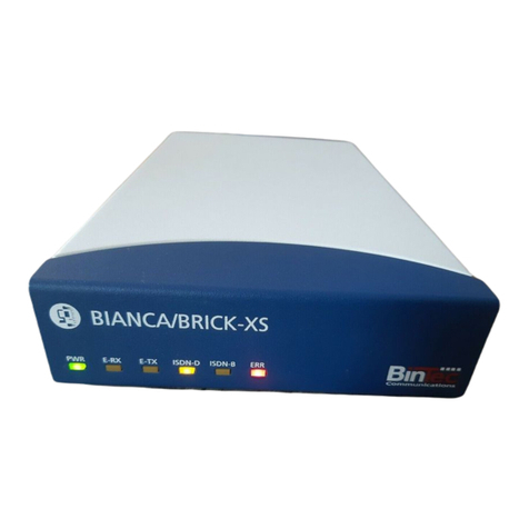
BinTec VICAS User manual

V!CAS
User’s Guide
Hardware and Installation
Version 1.2 October 1997
Document #70016

Copyright © 1997 BinTec Communications GmbH
All rights reserved
NOTE
The information in this manual is subject to change without notice.
This manual provides a description of the BinTec V!CASteleworking router. The
instructions included in this manual are compatible with software version 4.6.
While every effort has been made to ensure the accuracy of all information in
this document, BinTec Communications GmbH assumes no liability to any party
for any loss or damage caused by errors or omissions or by statements of any kind
in this document. BinTec and the BinTec logo are registered trademarks of BinTec
Communications GmbH.
All other product names and trademarks are the property of their respective
companies.
Warning
As a multi-protocol ISDN router this product is known to establish ISDN connections
as needed depending upon the system’s configuration. To avoid unwanted
charges the user is advised to continually monitor the product to ensure it oper-
ates within the bounds of the user’s expectations.
BinTec Communications is not responsible for incidental or consequential loss
of data, incurrance of connection costs, or other damages resulting from the
unsupervised use of the product.
All rights reserved. No part of this publication may be reproduced or transmitted in any form or by any
means–graphic,electronic,ormechanical–includingphotocopying, recordinginanymedium,taping,
or storage in an information retrieval systems, without the prior written permission of the copyright owner.
- am, lb
BinTec Communications GmbH October 1997

Declarations
FCC Notice — Class A Computing Device
This equipment has been tested and found to comply with the limits for a class A digital
device, pursuant to Part 15 of the FCC Rules and CSA Regulation C 108.8. These limits are
designed to provide reasonable protection against harmful interference in a commercial
environment. This equipment generates, uses and can radiate radio frequency energy and,
if not installed and used in accordance with the instruction manual, may cause harmful in-
terference to radio communications. Operation of this equipment in a residential area is
likely to cause harmful interference which the user will be required to correct at his/her
own expense.
FCC Notice — Class B Computing Device
NOTE: This equipment has been tested and found to comply with the limits for a class B
digital device, pursuant to Part 15 of the FCC Rules and meets all requirements of the Ca-
nadian Interference-Causing Equipment Regulations. These limits are designed to provide
reasonable protection against harmful interference in a residential installation. This equip-
ment generates, uses and can radiate radio frequency energy and, if not installed and used
in accordance with the instructions, may cause harmful interference to radio communica-
tions. However, there is no guarantee that interference will not occur in a particular instal-
lation. If this equipment does cause harmful interference to radio or television reception,
which can be determined by turning the equipment on and off, the user is encouraged to
try to correct the interference by one or more of the following measures:
•Reorient or relocate the receiving antenna.
•Increase the separation between the equipment and receiver.
•Connect the equipment into an outlet on a circuit different from that to which the
receiver is connected
•Consult the dealer or an experienced radio/T.V. technician for help.
The use of a non-shielded interface cable with the referenced device is prohibited. Changes
or modifications not expressly approved by BinTec Communications GmbH could void
the authority to operate the equipment.
CE Notice
The symbol means that the V!CAS adheres to the EMV (89/336/EWG) and voltage
(73/23/EWG) guidelines defined by the European Community.
Euro-Numeris
In addition to the guidelines defined by the EC, the V!CAS also adheres to
ISDN requirements in France and may be connected to Euro-Numeris.
GS
The GS (Geprüfte Sicherheit) symbol means that the V!CAS adheres to the standards de-
fined by the German safety regulations.
ISDN Ordering Codes (IOC) for the U.S.A.
V!CAS operates with the following IOCs: Capability Package ’S’ and
EZ-ISDN-1

Important Safeguards
This section describes the safety precautions the user should abide by when op-
erating this equipment.
• Transport this equipment in its original
packaging or by using appropriate mate-
rials to prevent against shock and impact.
• Before setting up this product for opera-
tion please make note of the accompa-
nying environmental requirements.
• Slots and openings in the unit are provid-
ed for ventilation. To ensure reliable oper-
ation and to protect it from overheating
these slots and openings must not be
blocked or covered.
• Condensation may occur externally or in-
ternally if this equipment is moved from a
colder room to a warmer room. When
moving this equipment under such condi-
tions, allow ample time for the equipment
to reach room temperature and to dry
before operating.
• Note that normal operation (in accord-
ance with IEC 950/EN-60950) is only possi-
ble when the external housing is left in
place (ventilation, fire prevention, and ra-
dio interference).
• Before supplying power, verify the power
rating identified on the marking label
complies with the local power source. This
equipment may be operated under the
following conditions:
100 - 240 VAC
50 - 60 Hz
max. 0.2 A
• Donotallowanythingtorestonanyofthe
attached cables and do not locate the
product where persons will walk or trip on
the cables.
• Connect this equipment only to an ap-
proved, properly grounded, and accessi-
ble socket outlet (this product includes a
safety tested power cable). To complete-
lyturnoff thisequipmentyou mustremove
the power cord from the system.
• Avoid connecting or disconnecting data
lines during lightning storms.
• Follow the accompanying instructions
when connecting the required cabling.
• Make sure no foreign objects or liquids
come into contact with the internal com-
ponents (danger of shock or short circuit).
• In an emergency (e.g., damaged exter-
nal housing or internal elements, liquid
spills) immediately remove the power
cord and notify customer service.
• Use only the supplied cables. If you use
other cables BinTec Communications
cannot assume responsibility for any re-
sulting damage.
• Electrostatic electricity can damage in-
ternal components. Ground yourself be-
fore touching any internal components.
• Never use water to clean this device. If
water reaches the internal parts, extreme
danger may result to the user or the
equipment.
• Never use scouring or abrasive cleaning
agents, or agents containing alkaline on
this device. Damage to the device’s exte-
rior may result.
•
NOTICE: The safeguards listed here apply
to all countries. A description of these
safeguardsinyourlocallanguage can be
found in Appendix A.

V!CAS User’s Guide v
1. Introduction
How to contact BinTec Communications ............................................. 1
How to get the latest software and documentation ........................... 2
About your User Documentation ............................................................ 2
Features ..................................................................................................... 3
What’s covered in this guide .................................................................. 5
Conventions used in this guide ............................................................... 6
2. Installing the V!CAS
Connecting the V!CAS to the LAN ......................................................... 8
Connecting the V!CAS to the ISDN ...................................................... 10
Connecting analog devices to the V!CAS ......................................... 10
Connecting the V!CAS to a PC or terminal ......................................... 11
The BOOT sequence .............................................................................. 11
Logging in for the first time .................................................................... 12
3. Working with the V!CAS
SNMP, MIBs, and V!CAS System Tables ................................................ 16
Configuration Files, Flash, and the TFTP ................................................ 18
Physical and Software Interfaces ......................................................... 19
1V!CAS
User’s Guide
Version 1.2
Contents

vi
V!CAS
Setup Tool vs. SNMP Shell ....................................................................... 20
Using Setup Tool ...................................................................................... 21
Menu Layout.......................................................................................... 21
Menu Structure...................................................................................... 22
Special Menu Commands................................................................... 23
Menu Navigation.................................................................................. 24
4. Setup Tool Menus
Setup Tool Main Menu ........................................................................... 26
Basic System Configuration ................................................................... 28
Hardware Interfaces .............................................................................. 32
LAN Interface : bnctp........................................................................................................................................................................................ 32
WAN Interface : 1bri....................................................................................................................................................................................... 35
Partner Management ............................................................................ 40
Configuring Protocols ............................................................................. 53
System Administration ............................................................................ 87
5. How do I Configure ...
Hardware Interfaces ............................................................................ 100
How do I configure an ISDN interface in general?......................... 100
How do I configure a leased line connection?............................... 102
How do I configure an Ethernet interface?..................................... 103
IP Features ............................................................................................. 104
How do I configure dialup TCP/IP access for an ISDN partner?.... 104
How do I configure Dialup Access to
CompuServe Online Services................................................ 106
How do I configure the V!CAS to accept
its IP address dynamically? ................................................... 107
How do I configure the V!CAS as a dynamic IP address server?.. 108
How do I configure Internet access for my LAN using NAT?.......... 109
How do I configure access lists to protect my network? ............... 111
How do I configure the V!CAS as a RADIUS client?........................ 113
How do I configure the V!CAS as a BOOTP relay agent?.............. 115
IPX Features ........................................................................................... 116
How do I connect my local and remote
IPX networks over ISDN? ........................................................ 116

vii
User’s Guide: Version 1.2
X.25 Features ......................................................................................... 118
How do I configure an X.31 link (X.25 in the D-channel)?.............. 119
How do I configure X.31 in the B-channel (Case A/Case B)?....... 121
How do I configure X.25 access for a host on my LAN? ................ 123
How do I configure ISDN dialup access for an X.25 partner? ....... 125
How do I route IP traffic over X.25 with MPX25?.............................. 126
How do I use the V!CAS as a TCP-X.25 bridge? .............................. 128
POTS Features ........................................................................................ 131
How can I configure my POTS ports if I only have one MSN?........ 131
How can I configure my POTS ports using more than one MSN? . 132
General .................................................................................................. 134
How can I retrieve accounting information (ISDN and TCP/IP)? .. 134
How do I use the V!CAS as a Bridge to link two LANs over ISDN?. 136
How can I improve security?............................................................. 138
How can remote users access the V!CAS’ status page? .............. 142
6. Troubleshooting
General Troubleshooting ..................................................................... 147
Debugging Tools ................................................................................... 147
debug................................................................................................... 147
isdnlogin............................................................................................... 148
bricktrace............................................................................................. 148
System Errors .......................................................................................... 148
Software Problems ................................................................................ 150
IPX Routing........................................................................................... 150
ISDN Connections ................................................................................. 152
POTS Connections ................................................................................ 156
7. Command Reference
The SNMP shell commands .................................................................. 157
BRICKtools for UNIX Commands .......................................................... 163
8. Hardware/Firmware Configuration
Hardware ............................................................................................... 166
Front Panel Indicators......................................................................... 166
The Back Plane.................................................................................... 167

viii
V!CAS
The Power Socket................................................................................ 168
The Network Ports................................................................................ 168
Telephony Ports................................................................................... 168
Serial Port.............................................................................................. 168
The Main Board ................................................................................... 168
Firmware ................................................................................................ 169
Upgrading System Software .............................................................. 169
BOOTmonitor ....................................................................................... 169
Automatic booting over TFTP ............................................................ 172
General System Specifications ............................................................ 173
A.Technical Data
Pin Assignments ..................................................................................... 174
ISDN S0interface ................................................................................. 174
POTS Port for analog equipment....................................................... 175
Serial Port.............................................................................................. 176
Ethernet Ports....................................................................................... 177
B. Index

V!CAS User’s Guide
1
1
How to contact BinTec Communications
Ways to contact BinTec Telephone number or address
Telephone +49 911 96 73 0
FAX +49 911 688 07 25
Mail BinTec Communications GmbH
Willstätterstraße 30
D-90449 Nürnberg
GERMANY
e-Mail Sales: [email protected]
Service: [email protected]
WWW http://www.BinTec.de
1INTRODUCTION
What’s covered
• How to contact BinTec Communications ...........................................1
• How to get the latest software and documentation..........................2
• About your User Documentation ..........................................................2
• What’s covered in this guide .................................................................5
• Conventions used in this guide..............................................................6

2 How to get the latest software and documentation
V!CAS
How to get the latest software and documentation
Please visit our WWW server for current information on all BinTec prod-
ucts. Via our WWW server BinTec provides you free of charge with the
most recent versions of:
• User documentation for your BinTec software/hardware
• System software for your V!CAS (see section Firmware in chap-
ter 8 on how to update the system software)
• Release notes for upgrading your V!CAS’ system software
• Windows software and UNIXTools applications
About your User Documentation
Your V!CAS documentation consists of this User’s Guide, the introductory
Getting Started and Los Geht’s manuals, and the online references BRICK-
ware for Windows,Software Reference, and The Management Information Base.
This document includes information for users that are familiar with
networking and telecommunications and describes the V!CAS hardware
and includes all the basic information you need to setup, configure, and
administer your V!CAS.
See the next section for an introductory list of features of your new
V!CAS. Following that is an overview of what’s covered in this guide.
Note: Your V!CAS belongs to BinTec’s successful family of
BIANCA/BRICK ISDN routers.
Whenever the term “BRICK” is used throughout the user
documentation, please be assured that these sections also
apply to your V!CAS.
!

Features 3
User’s Guide: Version 1.2
Features
“Now that I’ve got this new V!CAS—what can I do with it?”
Your V!CAS can serve a number of different purposes—most of them at
the same time. These include (but are not limited to) the following:
•Small PBX—connect up to two analog devices, such as telephones,
fax machines, or modems, to your V!CAS. This setup is especially
useful in small office environments.
You can make internal calls between the two connected telephones
free of charge, make two independent ISDN calls at the same time,
use one ISDN B channel for a phone call while transferring data on
the other, or even use both B channels for data transfer and still be
able to accept incoming calls via the Priority Voice Technology.
•Keypad Facilities—when you dial additional digits during an estab-
lished connection (Suffix Dialling / Nachwahl) from an analog tel-
ephone connected to a POTS port, these digits are not only sent as
DTMF tones, but also as keypad data packets.
You can access special functions on some external PBXs by using
Suffix Dialling (Nachwahl). Please refer to the manual of your PBX
for a description of its special functions.
•Remote TAPI server—you can use computer telephony applications
on your Windows 95 or Windows NT PC to dial for you, to open
up database entries of customers depending on their telephone
number, or as an intelligent answering machine.
For instructions on installing the Remote TAPI please refer to the
BRICKware for Windows online documentation.
Please note that the Remote TAPI is available for both Windows 95
and Windows NT, but not for Windows 3.x.
•Remote CAPI server—many PC communication applications use the
standardized CAPI interface to establish data connections—such
as terminal sessions, T-Online, Eufofiletransfer, or fax—over the
ISDN.

4 Features
V!CAS
• Included on your BinTec ISDN Companion CD you’ll find the RVS-
COM lite communications software for Windows 95 and NT, which
is a good and useful example for the power of CAPI applications.
•Router—use your V!CAS for routing IP or IPX packets received via
ethernet from your PC to your company LAN over the ISDN, and
vice versa.
• Bridge—use your V!CAS to connect two LANs.
•Remote configuration—configure your V!CAS from a remote site us-
ing the isdnlogin program (please refer to the Getting Started or Los
Geht’s manuals).
•Priority Voice Technology—incoming and outgoing voice calls take
precedence over existing 2-B-channel data connections (e.g. Multi-
LinkPPP).
This means that the data connection temporarily gives up one of its
B channels for the duration of the voice call.
•STAC compression—V!CAS supports the STAC compression ac-
cording to RFC 1974 and 1962 standards (PPP Stac LZS Compres-
sion Protocol and PPP Compression Control Protocol respectively)
which—depending on the data—can increase performance to a
factor of four.
The Stacker LZS algorithm is developed by Hi/fn Inc.
STAC compression on the V!CAS is also compatible with Cisco’s
proprietary STAC implementation which is automatically detected
at connection time.
These are but a few instances. You will find many more in examples
throughout this guide and the other manuals of your user documenta-
tion.
Note:YourISDNaccesshastosupportthe»Callwaiting«feature
(»Anklopfen« in Germany) for the incoming voice call to be
signalled to your V!CAS.
Without this feature, the Priority Voice Technology only
works for outgoing voice calls.

What’s covered in this guide 5
User’s Guide: Version 1.2
What’s covered in this guide
Chapter 1 Introduction is this chapter.
Chapter 2 Installing the V!CAS describes physically installing the
V!CAS on your LAN.
Chapter 3 Working with the V!CAS gives you a brief introduction to the
V!CAS and reviews some of the basic concepts that are central to working
with the V!CAS.
Chapter 4 Setup Tool Menus describes all the menus and variables
you’ll see when configuring the V!CAS’ features. This chapter is intended
as a reference to the Setup Tool menus.
Chapter 5 How do I Configure ... answers the most common questions
asked when configuring the V!CAS. If you just want to know how to con-
figure feature X, this is the first place to look.
Chapter 6 Troubleshooting is your guide to solving some of the most
common problems you may encounter when administering the V!CAS.
Chapter 7 Command Reference describes the shell commands availa-
ble from the V!CAS’ SNMP shell.
Chapter 8 Hardware/Firmware Configuration describes the V!CAS
hardware, and important tasks, such as upgrading the system software.
Appendix A Technical Data contains technical specifications for the
V!CAS, its communications ports, and security information in different
European languages.

6 Conventions used in this guide
V!CAS
Conventions used in this guide
To help you locate and interpret information easily, this manual uses the
following visual clues and typographic conventions.
Visual Clues
Lets you know what information you’ll
need before you start to configure a fea-
ture.
Marks the beginning of a list of steps re-
quired to configure a V!CAS feature.
References to information in other sections
or documents that may be helpful.
Points out important information such as
safety precautions and common pitfalls.
Typographic Conventions
Bold constant width type represents characters or
text that you must type in, exactly as shown.
Bold italic type represents special system table names.
Text enclosed in a box like this represents a
submenu or menu command found in Setup Tool.
✍
!
?
!
SYSTEM

V!CAS User’s Guide 7
2
You may have already installed and setup your V!CAS with
the help of the accompanying Getting Started and Los Geht’s
manuals. In that case you can skip over this chapter.
In this chapter, we’ll describe physically installing the
V!CAS on your LAN and attaching a serial console. Then
we’ll cover the brief BOOT sequence the V!CAS goes
through when starting up, and describe the login proce-
dures you should use when logging in for the first time.
1INSTALLING THE V!CAS
What’s covered
• Connecting the V!CAS to the LAN .......................................................8
• Connecting the V!CAS to the ISDN.....................................................10
• Connecting the V!CAS to a PC or terminal .......................................11
• The BOOT sequence.............................................................................11
• Logging in for the first time ..................................................................12

8 Connecting the V!CAS to the LAN
V!CAS
Connecting the V!CAS to the LAN
This section explains how to connect the V!CAS to your LAN. You can
connect your V!CAS to an ethernet using either the 10Base2 or 10BaseT
port on the back plane.
At boot time, and during normal operation mode the V!CAS, automat-
ically detects which LAN port is currently in use (however, only one port
per module may be used at a time).
Thin Coax
Cabling
10Base2
If your network is setup using thin coaxial cabling, stations on your net-
work are directly attached to the network cabling using a BNC connector
as shown in figure 1 below. A transceiver is usually not required.
1. Attach the BNC T-connector to the BNC port on the back plane
marked 10Base2.
2. Attach one end of the coaxial cable to an open end of the T-connector.
Align the notches in the cable end with those on the T-connector and
push the cable in, twisting about a quarter turn.
3. If the V!CAS is going to be the last station on your network you will
also need to attach a 50Ωterminator to the other end of the T-connec-
tor.
Thin coaxial Cabling requirements. Though thin coaxial cabling is less ex-
pensive and easier to install, distance and attachment restrictions are
Figure 1: BNC Connector
!

Connecting the V!CAS to the LAN 9
User’s Guide: Version 1.2
more stringent than for thick coaxial cabling. Thin coaxial segments have
a maximum distance of 185 meters and each segment can support up to
30 stations.
Twisted pair
cabling
10BaseT
If your network is setup using twisted pair (or telephone) wiring then in-
dividual stations are attached to the network through UTP (unshielded
twisted pair) connectors. A UTP connector is a telephone type (RJ-45)
connector also known as a western plug. A twisted pair cable connects
the UTP port of each station on the network to a central 10BaseT concen-
trator. You can attach the V!CAS to your ethernet using the 10BaseT port.
1. Attach a twisted pair cable to your V!CAS by inserting the 8 pin RJ-45
jack into the twisted pair port on the back plane marked 10BaseT.
2. Make a small loop into your twisted pair cable as close as possible to
the V!CAS and attach a ferrite to it.
3. Attach the other end of the twisted pair cable to an input port of your
concentrator
Figure 2: RJ-45 Western Plug with Ferrite
Note: You must use a ferrite with your twisted pair ethernet
cable. Otherwise the V!CAS may produce a higher
amount of electromagnetical radiation and therefore
possibly cause interference with other devices.
Ferrite
!
!

10 Connecting the V!CAS to the ISDN
V!CAS
Connecting the V!CAS to the ISDN
The V!CAS ISDN BRI port can be connected to your ISDN subscriber out-
let with the included ISDN cable or any standard 8 pin RJ-45 cable.
1. Attach the included ISDN cable (or any standard 8 pin RJ-45 cable) to
an ISDN subscriber outlet.
2. Attach the other end of the cable to the port marked ISDN S0on the
V!CAS.
Connecting analog devices to the V!CAS
You can connect up to two analog devices, such as telephones, fax ma-
chines, or modems, to the POTS1ports A and B of your V!CAS.
If you just connect V!CAS to the ISDN and two analog telephones to
portsAandByoucanusethefollowingfunctionswithoutanyfurthercon-
figuration.
• Free-of-charge internal calls between the two connected devices—
the device at port A can be reached by dialling »∗1«, the number for
port B is »∗2«. You can of course change these numbers if needed.
• Youcancallanyexternalnumberbysimplydiallingit.IfyourV!CAS
is connected to the ISDN through an external PBX, you may have to
dial a prefix code for external calls.
For instructions on how to configure the phone numbers for the POTS
ports please refer to pages 84 ff.
1. »Plain old telephone service«
!
Note: Please note, however, that these devices must be configured
to use tone dialling (Mehrfrequenzwahl in Germany), and not
pulse selection (Impulswahl in Germany).
Also make sure to use cables with the correct pinout (see
Appendix A).
!

Connecting the V!CAS to a PC or terminal 11
User’s Guide: Version 1.2
Connecting the V!CAS to a PC or terminal
A PC or terminal can be connected directly to the V!CAS using the 9 pin
serial port on the backplane marked serial console. Please use the includ-
ed laplink cable for this purpose. Initially use the following communica-
tions parameters.
Data Rate: 9600 bps
Data Bits: 8
Parity Bit: None
Stop Bit: 1
Terminal Type: VT100 (or ANSI)
SW Handshake: XON/XOFF
HW Handshake: none
The default data rate used by the V!CAS can be set using the BOOTmoni-
tor which is described in Chapter 8.
The BOOT sequence
Each time you power up the system, the V!CAS moves between three dif-
ferent modes. The LEDs on the front panel correspond to stages within
each mode. The section Front Panel Indicators in Chapter 8 describes their
respective meanings.
Power-up Mode
BOOTmonitor Mode
Normal Operation Mode
During Power-up Mode, the V!CAS performs various self-tests de-
signed to verify the integrity of the system and to ensure the internal cir-
cuitry is working properly.
Note: Some PBXs and exchanges may, however, refuse to forward
calls without an ISDN calling party number. In these cases
you will have to further configure your V!CAS before you
can make external calls.
!

12 Logging in for the first time
V!CAS
In BOOTmonitor mode, the V!CAS waits 4 seconds for the user to
press the spacebar which activates the BOOTmonitor. See BOOTmonitor,
page 169, in Chapter 8 for information on using the BOOTmonitor.
Normal Operation Mode is entered once the V!CAS is finished booting
its internal system software.
Normally, the whole process only takes about 15 seconds. You can see
the results of the various tests on your terminal display.
After the system comes up, the V!CAS starts various system daemons
depending on which features are licensed on your V!CAS. The system
then presents a login prompt to the screen of a connected serial console.
Logging in for the first time
To log into the V!CAS for the first time;
enter admin at the login prompt, then
enter bintec when prompted for a password.
Note that the V!CAS uses three different login names and passwords
to grant various levels of access to configuration information. These user
### V!CAS - Start-up ###
Starting DRAM Test : ................................ ok.
Starting FLASH Test : .... [0xc3b2] ok.
Starting ISDN Chip Test : .... ok.
Starting ISDN Loopback Test : .... ok.
Starting ISDN Bus Test : .... ok.
Starting Ethernet Chip Test : .... ok.
Starting Ethernet Loopback Test M1: .................... ok.
Starting Ethernet Loopback Test M2: .................... ok.
### V!CAS (Hardware Release 1.2, Firmware Release 1.7) ok ###
Press <sp> for boot monitor or any other key to boot system
Booting Image from Flash ROM
Checking image ... OK
Writing image to RAM (Release 4.6.1) .......................OK (1396684 bytes)
Booting BOSS...
BOSS kernel v2.0 (V!CAS)
Copyright (c) 1996 by BinTec Communications GmbH
Version 4.6 Revision 1 from 97/10/01 00:00:00
The system is coming up.
The system is ready.
Table of contents
Other BinTec Network Router manuals
BinTec
BinTec RV120-4G User manual

BinTec
BinTec BinGO! DSL II User manual
BinTec
BinTec X8500 User manual
BinTec
BinTec NetRACER User manual
BinTec
BinTec X4000 User manual
BinTec
BinTec X2250 Instruction manual
BinTec
BinTec RS123 User manual

BinTec
BinTec XGeneration X2301 User manual

BinTec
BinTec BIANCA/BRI User manual
BinTec
BinTec X3200 User manual

BinTec
BinTec elmeg T484 User manual
BinTec
BinTec X4100 User manual
BinTec
BinTec X1000 User manual
BinTec
BinTec BinGO Plus User manual
BinTec
BinTec BIANCA/BRICK-XL2 User manual
BinTec
BinTec BinGO Plus User manual
BinTec
BinTec BinGO! DSL User manual

BinTec
BinTec BinGO Plus User manual

BinTec
BinTec M2 User manual
BinTec
BinTec 4Ge-LE User manual
